画中漫游原理
animated drawings 的原理
animated drawings 的原理动画绘画,又称为“动态绘画”或“动画绘图”,是一种将静态图像以快速的连续动作形式呈现的艺术形式。
它通过将一系列静态图像(帧)以每秒24到30帧的速度连续播放,利用视觉暂留效应使观众感知到一种平滑流畅的运动。
动画绘画广泛应用于电影、电视、广告、游戏、教育等领域。
动画绘画的原理主要涉及两个方面:视觉暂留效应和帧动画制作。
首先,视觉暂留效应是动画绘画能够呈现连续运动的基础。
当观众在短时间内接连看到一系列静止的图像时,这些图像在大脑中会被持续记忆和合成为连续的动态画面。
这是因为人眼的视觉感知延迟和大脑的图像处理机制所导致的现象。
通过调整图像的播放速度和帧率,可以让观众感受到不同的运动速度和流畅度。
通常,帧率越高,动画的流畅度就越高。
其次,动画绘画的制作过程通常包括以下几个步骤:规划、分镜、绘画、扫描、清理和彩色等。
规划阶段主要确定动画的整体结构、情节和角色设定。
分镜脚本则是将整个动画分解为一系列的镜头和画面。
绘画阶段通常由动画师根据分镜脚本来绘制每一帧的图像。
在绘画完成后,图像会被扫描到计算机中进行后续处理。
清理阶段则是将扫描的图像进行修整和润色,消除不必要的线条和杂质。
最后,彩色阶段通过给图像上色来增加其真实感和吸引力。
动画绘画的制作过程中,有一种常用的技术称为“在动画帧之间进行绘画(Tweening)”。
通过在起始帧和结束帧之间绘制中间帧,计算机可以自动推断出中间步骤的动画图像。
这样可以大大减少绘画的工作量,提高制作效率。
在这个过程中,关键帧和中间帧的绘画将由计算机软件自动完成。
这项技术对于制作复杂的动画效果非常有用。
动画绘画不仅仅在影视制作中应用广泛,也在日常生活中随处可见,例如电视广告中的卡通形象、手机APP中的动画特效、网页上的交互动画等等。
随着计算机技术的不断发展和普及,动画绘画的制作工具和方法也在不断更新和改进。
越来越多的艺术家和创作者正在通过动画绘画展示他们的创意和想象力。
midjourney 绘画原理

midjourney 绘画原理绘画是一门艺术形式,通过画笔、颜料和纸张等工具将艺术家的创意和想法表达出来。
而midjourney 绘画原理则是一种独特的绘画方法,其核心理念是在绘画过程中注重探索和旅程,而非仅仅关注最终的作品。
midjourney 绘画原理的一个重要概念是“中途旅程”。
艺术家在创作过程中并不仅仅专注于最终的目标,而是更加关注每一个绘画过程中的瞬间和变化。
这种思维方式可以帮助艺术家更好地理解绘画的本质,同时也能够带来更加自由和灵感的创作体验。
midjourney 绘画原理还强调了“探索”的重要性。
艺术家在绘画过程中应该保持一种探索的心态,不断尝试不同的技法和风格,勇于冒险和突破。
通过不断地探索,艺术家可以发现新的创作方向和灵感源泉,使作品更加丰富多样。
在midjourney 绘画原理中,艺术家还需要注重“观察”。
观察是绘画过程中必不可少的一环,艺术家需要仔细观察对象的形态、色彩和纹理等细节,以便能够准确地表达出来。
通过观察,艺术家可以更好地理解事物的本质和特点,从而在作品中传达出真实而生动的感受。
midjourney 绘画原理还鼓励艺术家在绘画过程中保持一种“灵感”的状态。
艺术家应该学会倾听内心的声音,从个人经验和情感中汲取灵感,并将其融入到作品中。
灵感是绘画中的一种力量,可以赋予作品更加深刻和独特的内涵。
在midjourney 绘画原理中,艺术家还要注重“表达”。
绘画是一种表达的艺术形式,艺术家应该学会用图像语言来传达自己的思想和情感。
通过细腻的线条、丰富的色彩和独特的构图,艺术家可以创造出生动而有力的作品,引发观者的共鸣和思考。
midjourney 绘画原理的核心是追求创造力和独特性。
艺术家应该勇于表达自己独特的艺术观点和创作风格,不被传统观念所限制。
通过发挥想象力和创造力,艺术家可以创作出独一无二的作品,展示出自己的独特艺术魅力。
midjourney 绘画原理是一种注重探索和旅程的绘画方法。
画画的基本原理

画画的基本原理画画的基本原理主要包括色彩、光线、线条、透视和节奏等元素。
这些元素在绘画中起着至关重要的作用,它们共同作用,使绘画作品能够呈现出立体感、空间感、色彩感和情感氛围。
1. 色彩:色彩是绘画中的基本元素,不同的色彩可以引发不同的情感反应。
通过对色彩的选择、搭配和对比,艺术家可以创造出独特的视觉效果和情感氛围。
2. 光线:光线在绘画中起着重要的作用,它可以突出或强调画面的某些部分,也可以为画面营造出特定的氛围。
通过明暗的对比和光线的方向,艺术家可以创造出立体感和深度感。
3. 线条:线条是绘画中的重要元素,它可以用来勾勒形状、表现纹理和表达动态。
通过不同的线条类型和运用方式,艺术家可以表现出不同的视觉效果和情感特征。
4. 透视:透视是绘画中表现空间感的重要手段。
通过近大远小、消失点等透视原理,艺术家可以创造出三维空间的视觉效果。
5. 节奏:节奏在绘画中是指画面元素的重复、变化和连续等关系。
通过节奏的把握,艺术家可以让画面更加有秩序感和动态感。
此外,构图、艺术史、艺术理论、艺术评论等也是绘画的基本原理。
构图是指画面的布局和安排,它可以使画面更加有层次感和均衡感。
艺术史是研究绘画的发展历程,通过对艺术史的了解,艺术家可以吸取前人的经验,创新和发展自己的绘画技巧。
艺术理论则是研究绘画的本质和价值,它可以帮助艺术家理解自己的创作目的和意义。
艺术评论是对绘画作品的评价和分析,它可以帮助艺术家了解自己的优点和不足之处,进一步提高自己的创作水平。
总之,画画的基本原理是理解和掌握绘画语言的关键所在,只有掌握了这些基本原理,才能更好地表达自己的想法和感受,创作出更加有深度和内涵的绘画作品。
绘画透视原理与技法

绘画透视原理与技法绘画是一门艺术形式,通过色彩、线条和光影等元素来表现对象和场景。
而透视则是绘画中非常重要的一种技法,通过精确地表现空间和深度感,使画面更加逼真和立体。
本文将探讨绘画透视的原理和一些常用的技法。
一、透视的基本原理透视是指通过艺术手法将三维空间的物体表现在二维画面上,使观者获得一种立体感。
透视原理主要包括线性透视和气氛透视两种。
1. 线性透视线性透视又称为单点透视,是最基本的透视原理。
它通过将画面中的水平线和一个特定的点(称为消失点)连接起来,从而展示出广阔深远的空间感。
在线性透视中,物体与观察者之间的距离和角度是决定画面透视效果的关键。
通常情况下,离观察者较远的物体将显得较小,而离观察者近的物体则会显得较大。
2. 气氛透视气氛透视也称为大气透视,是通过色彩和明暗的变化来表现远近和深度感。
在气氛透视中,远处的物体会出现明亮且颜色饱和度较低的现象,而近处的物体则会显得较暗且颜色饱和度较高。
这种透视原理是由空气中的微粒通过散射和吸收光线的方式产生的,因此在绘画中通过运用明暗、色彩和层次感等因素来展现远近和深度感。
二、透视的常用技法在绘画中,有许多技法可以帮助艺术家更好地表现透视效果。
以下是一些常用的技法。
1. 线性透视技法线性透视技法包括单点透视、双点透视和多点透视等。
其中,在单点透视中,艺术家需要选择一个消失点,然后通过在画面中合理运用水平线和消失点来表现虚线、实线和交叉线等,以展示出深度和立体感。
双点透视和多点透视则相对复杂一些,需要在画面中选择两个或多个消失点,然后根据不同的投射角度来描绘物体的形状和大小。
2. 色彩透视技法色彩透视技法主要通过运用明暗、色调和饱和度等因素来展现远近和深度感。
艺术家可以运用明暗对比将近处的物体描绘为较暗的色彩,而远处的物体则描绘为较亮的色彩。
此外,运用色调和饱和度的变化也可以增加远近效果,例如远处的物体可以采用较冷色调和低饱和度,而近处的物体则可以采用较暖色调和高饱和度。
曼陀罗绘画原理

曼陀罗绘画原理
曼陀罗绘画原理
曼陀罗绘画是一种运用光影色调、节奏艺术技法结合原创感的艺术表现形式,以高度的视觉感官与心灵感受为表现核心,运用光影色调的技巧去叙写我们愿景与思想、精神境界的抒情艺术。
曼陀罗绘画具体的画法原理,就是一种心灵的传达,重点在于形象的意境,体现出被写者的情感情绪。
它以抽象的笔触与勾勒出的静谧意境为营建,以光影色调的变化为衬托,以节奏艺术的运用为平衡,以自由意志的运用为力量。
通过敏锐捕捉到被写者所呈现的情绪与气息,用笔尖精准表达出感性内心的交融幻影,为被写者打造一种张力感,让作者自由追求精致的表现意境,把最真挚的情感贯穿于每一幅画中。
曼陀罗绘画的核心精神在于融合灵性与情感展示,让被写者的精神从画面跃起,以最新颖的笔触给我们最原始的感受,以一种变幻的艺术灵感,触及当下最原生的情怀。
让作者有画,让观者有悟!
- 1 -。
美术中近大远小的实验原理
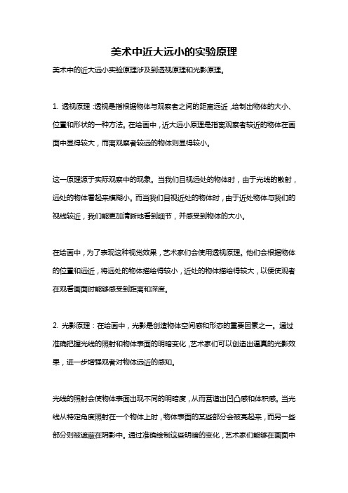
美术中近大远小的实验原理美术中的近大远小实验原理涉及到透视原理和光影原理。
1. 透视原理:透视是指根据物体与观察者之间的距离远近,绘制出物体的大小、位置和形状的一种方法。
在绘画中,近大远小原理是指离观察者较近的物体在画面中显得较大,而离观察者较远的物体则显得较小。
这一原理源于实际观察中的现象。
当我们目视远处的物体时,由于光线的散射,远处的物体看起来模糊小。
而当我们目视近处的物体时,由于近处物体与我们的视线较近,我们能更加清晰地看到细节,并感受到物体的大小。
在绘画中,为了表现这种视觉效果,艺术家们会使用透视原理。
他们会根据物体的位置和远近,将远处的物体描绘得较小,近处的物体描绘得较大,以便使观者在观看画面时能够感受到距离和深度。
2. 光影原理:在绘画中,光影是创造物体空间感和形态的重要因素之一。
通过准确把握光线的照射和物体表面的明暗变化,艺术家们可以创造出逼真的光影效果,进一步增强观者对物体远近的感知。
光线的照射会使物体表面出现不同的明暗度,从而营造出凹凸感和体积感。
当光线从特定角度照射在一个物体上时,物体表面的某些部分会被亮起来,而另一些部分则被遮蔽在阴影中。
通过准确绘制这些明暗的变化,艺术家们能够在画面中再现物体的立体感。
对于近大远小的表现,光影原理的应用尤为重要。
远离光源的物体会被照射得较暗,而靠近光源的物体则会被照射得较亮。
同时,由于光线在空气中的传播会受到空气颗粒的干扰,远处的物体会因此而显得更加模糊。
艺术家们会利用光影的效果,通过在画面中准确刻画物体的明暗度和细节来表现物体的远近距离。
综上所述,美术中的近大远小实验原理涉及到透视原理和光影原理。
通过准确把握物体的远近距离和光影变化,艺术家们可以在绘画中创造出逼真的立体感和空间感。
这种技巧可以让观者更好地感受到距离和深度,增强作品的艺术效果。
柳卡图原理

柳卡图原理柳卡图原理,又称为卡通原理,是一种用来表现人物或物体在动作中的形变和姿态的绘画技巧。
它是由迪士尼动画公司的动画师柳卡图所创立的,被广泛应用于动画、漫画、游戏设计等领域。
柳卡图原理的核心思想是通过捕捉和表现物体在运动过程中的变形和姿态,使得角色动作更加生动和富有表现力。
柳卡图原理的基本原理是通过对物体在运动中的形态变化进行观察和分析,然后将这些变化表现在绘画或动画中。
它强调的是在动作中捕捉物体的变形和姿态,以及如何将这些变化表现出来,从而使得角色在动作中更加生动和有张力。
柳卡图原理的核心概念包括挤压、拉伸、重量、速度、延迟等,这些概念被广泛应用于动画制作中,成为了动画师们必备的技能之一。
在柳卡图原理中,挤压和拉伸是非常重要的概念。
挤压是指在物体受到外力作用时,会产生形变,而拉伸则是指物体在速度加快或减慢时,会产生相应的拉伸变形。
通过对挤压和拉伸的运用,可以使得角色在动作中更加生动和有力量感。
此外,重量和速度也是柳卡图原理中需要重点考虑的因素。
在动画中,通过对角色的重量和速度的表现,可以使得动作更加真实和有力量感。
延迟是柳卡图原理中的另一个重要概念。
它指的是在物体受到外力作用时,会产生一定的延迟效果。
在动画中,通过对角色动作的延迟进行表现,可以使得动作更加流畅和自然。
柳卡图原理的应用不仅局限于动画领域,它也被广泛运用于漫画、游戏设计等领域。
通过对柳卡图原理的理解和应用,可以使得角色在各种媒介中更加生动和有表现力。
总的来说,柳卡图原理是一种用来表现人物或物体在动作中形变和姿态的绘画技巧,它通过捕捉和表现物体在运动过程中的变形和姿态,使得角色动作更加生动和富有表现力。
柳卡图原理的核心概念包括挤压、拉伸、重量、速度、延迟等,这些概念被广泛应用于动画、漫画、游戏设计等领域。
通过对柳卡图原理的理解和应用,可以使得角色在各种媒介中更加生动和有表现力。
绘画的基本原理

绘画的基本原理绘画是一门艺术形式,通过画笔、颜料以及其他绘画工具将观察到的事物表达出来。
它涉及到许多基本原理,能够帮助艺术家创造出真实、独特的视觉体验。
本文将介绍绘画的基本原理,并探讨如何运用这些原理创作出精彩的绘画作品。
一、线条与轮廓线条是绘画的基本元素之一,它通过一笔一划勾勒出物体的外形和内部结构。
线条可以分为实线和虚线,可以粗细、粗糙或平滑。
艺术家可以通过线条的变化来表达物体的质感和形态,不同的线条呈现出不同的效果。
轮廓是线条在物体的边缘形成的线条,能够帮助观众更好地理解物体的形状和比例。
二、色彩与明暗色彩是绘画中最重要的元素之一,通过使用不同的颜料和调色技巧,艺术家能够创造出丰富多样的色彩效果。
色彩可以传达情感、表现光线和热度,对于绘画作品的效果起着重要的作用。
明暗是色彩的亮度,通过在绘画中运用明暗的对比,艺术家能够创造出立体感和质感,并引导观众的目光流动。
三、透视与构图透视是绘画中表示空间和深度的重要手法。
通过运用透视原理,艺术家可以在平面上呈现出三维的效果,使观众的目光在画面中游走。
透视原理包括线性透视、大视角透视和小视角透视等不同形式,它们能够创造出不同的空间感。
构图是决定画面组织和平衡的过程,合理的构图能够引导观众的目光,创造出有力的视觉效果。
四、比例与形态比例是绘画中表现物体大小和相对关系的重要原则。
正确的比例能够使绘画作品看起来更真实、更有说服力。
艺术家需要观察和捕捉物体的真实比例,也可以适当地进行改变以达到自己的艺术效果。
形态是指物体的形状和结构,艺术家可以通过绘画技巧和观察来准确地表达物体的形态,使画作更加生动和鲜活。
五、质感与纹理质感是绘画中表现物体表面触感的要素。
艺术家通过使用不同的绘画技法,如交叉刷、拍、涂抹等,能够创造出各种不同的质感效果,如光滑、粗糙、柔软等。
纹理是物体表面的纹路和纹理,艺术家可以通过绘画技巧和细节的处理来表现出物体的纹理,增加作品的复杂性和立体感。
- 1、下载文档前请自行甄别文档内容的完整性,平台不提供额外的编辑、内容补充、找答案等附加服务。
- 2、"仅部分预览"的文档,不可在线预览部分如存在完整性等问题,可反馈申请退款(可完整预览的文档不适用该条件!)。
- 3、如文档侵犯您的权益,请联系客服反馈,我们会尽快为您处理(人工客服工作时间:9:00-18:30)。
Tour Into the Picture:Using a Spidery Mesh Interface to Make Animation from a Single ImageYouichi Horry*‡ Ken-ichi Anjyo† Kiyoshi Arai*Hitachi, Ltd.ABSTRACTA new method called TIP (Tour Into the Picture) is presented for easily making animations from one 2D picture or photograph of a scene. In TIP, animation is created from the viewpoint of a camera which can be three-dimensionally "walked or flown-through" the 2D picture or photograph. To make such animation, conventional computer vision techniques cannot be applied in the 3D modeling process for the scene, using only a single 2D image. Instead a spidery mesh is employed in our method to obtain a simple scene model from the 2D image of the scene using a graphical user interface. Animation is thus easily generated without the need of multiple 2D images.Unlike existing methods, our method is not intended to construct a precise 3D scene model. The scene model is rather simple, and not fully 3D-structured. The modeling process starts by specifying the vanishing point in the 2D image. The background in the scene model then consists of at most five rectangles, whereas hierarchical polygons are used as a model for each foreground object. Furthermore a virtual camera is moved around the 3D scene model, with the viewing angle being freely controlled. This process is easily and effectively performed using the spidery mesh interface. We have obtained a wide variety of animated scenes which demonstrate the efficiency of TIP.CR Categories and Subject Descriptors: I.3.3 [Computer Graphics]: Picture/Image Generation - viewing algorithms; I.3.7 [Computer Graphics] Three-dimensional Graphics and Realism, AnimationAdditional Keywords: graphical user interface, image-based modeling/rendering, vanishing point, field-of-view angle1 INTRODUCTIONMaking animation from one picture, painting, or photograph is not a new idea. Such animations have been mainly used for∗Central Research Laboratory, 1-280 Higashi-Koigakubo Kokubunji Tokyo 185{horry, arai}@crl.hitachi.co.jp†Visualware Planning Department, 4-6 Kanda-Surugadai Chiyoda Tokyo 101anjyo@cm.head.hitachi.co.jp‡Currently visiting INRIA Rocquencourt, Domaine de Volceau - Rocquencourt 78153 Le Chesnay Cedex France horry@bora.inria.frart and entertainment purposes, often with striking visual effects. For instance, 2D animations are commonly seen, where 2D figures of persons or animals in the original image move around, with the 2D background fixed. In relatively simple cases, these animations may be created using traditional cel animation techniques. If the animations are computer-generated, then 2D digital effects, such as warping and affine transformations, can also be employed.However, it is still hard and tedious for a skilled animator to make computer animations from a single 2D image of a 3D scene without knowing its 3D structure, even if established digital techniques are fully available. When the input image is given in advance, first of all, the animator has to make the 3D scene model by trial and error until the projected image of the model fits well with the input image of the scene. At the very beginning of this process, the virtual camera position in 3D space must also be known as one of the conditions for the input image to be regenerated from the scene model. This poses the question, how is the camera position known by a single image ? Unfortunately existing approaches to create models directly from photographs, such as image-based techniques, require multiple input images of photographs, and the cases discussed in this paper are outside their scope. If animating a painting is desired, making the animation may become more difficult, because a painting does not give as precise information for creating the 3D scene model as a photograph does.The best possible approach currently available to making animation from a single image therefore depends largely on the skill, sense, and eye of the animators, though this naivety may place an excessive and tedious task load on the animators. They can then develop the scene structure freely, using vague and incomplete information included in the input to animate the scene to their liking. The scene structure, however, may still be incomplete. A more straightforward method is thus desired for creating the scene animation, in which the 3D modeling process of the scene is rather simplified or skipped.In this paper we propose a simple method, which we call TIP (Tour Into the Picture), for making animations from one 2D picture or photograph of a scene. This method provides a simple scene model, which is extracted from the animator’s mind. Thus the scene model is not exactly 3D structured, but is geometrically just a collection of “billboards” and several 3D polygons. Therefore, the animations obtained with our method are not strictly three-dimensional. However, as we show, the proposed method allows easy creation of various animations, such as “walk-through” or “fly-through”, while visually giving convincing 3D quality.1.1 Related workIf a photograph is used as the 2D input image, then image-based methods, including [2 , 4, 7] may be used effectively. In [2], the panoramic image is made from overlapping photographs taken by a regular camera to represent a virtual environment, so that real-time walk-through animations can be made with the viewpoint fixed. The method in [7] provides animations, with many closely spaced images being required as input, and its theoretical background largely relies on computer vision techniques. This work can also be considered to belong to the category of techniques for light field representation [6], which gives a new framework for rendering new views using large arrays of both rendered and digitized images. Similarly, in [4] a "sparse" set of photographs is used for existing architectural scenes to be animated. Though the input condition is improved due to architectural use, multiple input images are still required. Despite successful results with these image-based approaches, we need a new methodology, especially for dealing with the situations where the input is a single photograph.For paintings or illustrations, there are relatively fewer research reports on their animation. A new rendering technique was presented in [8] for making painterly animations. Assuming that the 3D geometric models of the objects in a scene are known in advance, animations in a painterly style are then made by the method using 3D particles and 2D brush strokes.Morphing techniques including [1] provide 3D effects visually, requiring at least two images as input, although actuallyonly 2D image transformations are used. For example the view interpolation technique [3] is an efficient application of morphing, which generates intermediate images, from images prestored at nearby viewpoints. View morphing [9] also gives a strong sense of 3D metamorphosis in the transition between images of the objects. Then we note that most of these techniques require no knowledge of 3D shape in morphing. Existing methods cited above work effectively, when multiple input images are available, or when the 3D geometric structure of a scene to be animated is known in advance. Our approach treats the cases when one input image of a scene is given without any knowledge of 3D shapes in the scene. Theoretically it is impossible to create an animation from a single view of the scene. Instead, our approach actually gives a new type of visual effect for making various animations, rather than constructing a rigid 3D model and animation of the scene.1.2 Main IdeaIf we consider traditional paintings or landscape photographs, their perspective views give a strong impression that the scenes depicted are 3D. It is hard for us to find an exact position for the vanishing point of the scene in the picture. In particular, for paintings or drawings, the vanishing point is not precisely prescribed, being largely dependent on the artist’s imagination. Therefore, rigid approaches, such as computer vision techniques, are not valid for the purpose of exactly finding the vanishing point. However, it is relatively easy for us to roughly specify the vanishing point, by manually drawing guide lines for perspective viewing. Then we can expect that the “visually 3D” geometry of the scene’s background is defined as a simple model (with polygons, for instance) centering around the user-specified vanishing point. Similarly, in many cases, we can easily tell the foreground objects from the background through our own eyes.A simple and intuitive model of the foreground object can then be like a “billboard” that stands on a polygon of the background model.The main idea of the proposed method is simply to provide a user interface which allows the user to easily and interactively perform the following operations.(1) Adding “virtual” vanishing points for the scene - Thespecification of the vanishing point should be done by the user, not automatically, as mentioned above.(2) Distinguishing foreground objects from background - Thedecision as to whether an object in the scene is near the viewer should be made by the user, since no 3D geometry of the scene is known. In other words, this means that the user can freely position the foreground object, with the camera parameters being arranged.(3) Constructing the background scene and the foregroundobjects by simple polygons - In order to approximate the geometry of the background scene, several polygons should be generated to represent the background. This model is then a polyhedron-like form with the vanishing point being on its base. The “billboard”-like representation and its variation are used for foreground objects.These three operations are closely related to each other so that the interactive user interface should be able to provide their easy and simultaneous performance. A spidery mesh is the key to fulfilling this requirement.The proposed method is outlined as follows. Fig. 1 shows the process flow.After an input image is digitized (Fig.1 (a)), the 2D image of the background and 2D mask image of the foreground objects are made (Figs. 1 (b), (c)). TIP uses a spidery mesh to prescribe a few perspective conditions, including the specification of a vanishing point (Fig. 1 (d)). In the current implementation of TIP, we can specify one vanishing point for a scene. This is not restrictive because many paintings, illustrations, or photographs can actually be considered one-point perspective, and because, as demonstrated later, the one-point perspective representation using spidery mesh works very well even for the cases where it is hard for us to tell if the input is one-point perspective or not. Next, the background is modeled with less than five 3D rectangles (Fig. 1 (e)), and simple polygonal models for the foreground objects are also constructed (Fig. 1 (f)). Finally, by(b) Background imagechanging the virtual camera parameters (Fig. 1 (g)), images at different views are rendered (Fig. 1 (h)), so that the desired animation is obtained.In section 2 the modeling process of the 3D scene (Figs. 1 (a) -(f)) in TIP is described. In section 3, after the rendering technique (Figs. 1 (g), (h)) is briefly mentioned, several animation examples are shown, which demonstrate well the efficiency and usefulness of the proposed method. Conclusions and future research directions of the method are summarized in section 4.2 SCENE MODELING FROM A SINGLE IMAGEIn our method we use one picture or photograph of a 3D scene as input, from which we wish to make a computer animation. Then we specify one “virtual” (i.e. “user-specified”) vanishing point for the scene. As described later, this does not always mean that the input image must be one-point perspective. For convenience, the line that goes through the vanishing point and view point is vertical to the view plane. As for camera positioning, default values of camera position, view-plane normal, and view angle (field-of-view angle) are assigned in advance (see [5] for technical terms). These parameters are changed later using our GUI (Graphical User Interface) in 3.1 for making animations. For simplicity, the input images used are taken by the virtual camera without tilting, (though actually this condition can easily be eliminated). This means that the view up vector, which is parallel to the view plane in this paper, is vertical to the ground of the 3D scene to be modeled.2.1 Foreground Mask and Background ImageIn the modeling process we first derive two types of image information from the input 2D image: foreground mask and background image. Let F1, F2 ,..., F p be subimages of the input image I, each of which is supposed to correspond to a foreground object in the 3D scene and is relatively close to the virtual camera. In practice the subimages {F i}1_i_p are specified by a user and are modeled as polygonal objects in the corresponding 3D scene (see 2.3). The foreground mask is then defined as the 2D image consisting of {αi}1_i_p, where αi is a grey-scaled masking value (α-value) of F i. The background image is the 2D image which is made from I by retouching the traces of {F i} after the subimages {F i} are removed from I. The retouching process consists of occluding the traces of these subimages using color information for the neighborhood of each point (pixel) in F i.There is commercially available software, such as 2D paint tools, that enable us to easily make 2D images for the foreground mask and the background, from an input image. Fig.1 presented an example. Fig.1(a) showed the input image (of a photograph). The background image in Fig. 1 (b), as well as the foreground mask in Fig. 1 (c), were obtained using a standard 2D paint tool. To get the foreground mask in Fig. 1 (c), a street lamp and two persons were selected by the user, as the subimages {F i} mentioned above.2.2 Specifying the Vanishing Point and Inner RectangleIn order to model the 3D scene from the input image, we use our software called TIP, starting with the specification of the vanishing point of this image. TIP employs a unique GUI with a spidery mesh, which plays an essential role not only in the specification process but also in the processes thereafter.Fig. 2 (a) shows the initial state of the spidery mesh in applying it to the input image in Fig. 1 (a). In general, as illustrated in Fig. 2 (a), the spidery mesh is defined as the 2Dfigure consisting of: a vanishing point; and an inner rectangle, which intuitively means the window out of which we look at infinity; radial lines that radiate from the vanishing point; an outer rectangle which corresponds to the outer frame of the input image. Each side of the inner rectangle is made to be parallel to a side of the outer rectangle. In TIP, the specification of the inner rectangle is done as well as that of the vanishing point. It should then be noted that, as described later, the inner rectangle is also used to specify the rear window in the 3D space (see 2.3 and 2.4). The rear window is a border that the virtual camera, which will be used in making an animation, cannot go through. The inner rectangle is consequently defined as the 2D projection of this window onto the 2D image space (i.e., the projection plane). In practice the 3D window is considered to be so distant from the current (initial) position of the virtual camera, that the camera does not zoom in beyond this window from the current position.We now describe how to use the spidery mesh in order to specify the vanishing point. As described above, we then position the inner rectangle, along with the vanishing point. First we consider typical cases where the vanishing point is located in the input image (i.e., within the outer rectangle of the spidery mesh). Fig. 3 (a) is such a case. Then, using a pointing device (a mouse in the current implementation), we can control the geometry of the spidery mesh using the following functions.[a] Deformation of the inner rectangle - If the right-bottomedge of the inner rectangle is dragged with the pointingdevice, then the left-top edge of the rectangle is fixed, andthe right-bottom edge is moved according to the dragging(see Fig. 3 (a)).[b] Translation of the inner rectangle - If we drag a point onone of the sides of the rectangle (except the point at theright-bottom corner), then the rectangle is moved by thedragging distance ( Fig. 3 (b)).[c] Translation of the vanishing point - If the vanishing pointis dragged, then it is translated. The four radial lines, which are drawn boldly in Fig. 3, are also moved under the condition that these radial lines always go through the four edges of the inner rectangle, respectively (Fig. 3 (c)). If the cursor is dragged out of the inner rectangle, then the vanishing point is moved in the direction, and by the distance of, the dragging. Conversely, if one of these bold radial lines is translated by moving its edge on the outer rectangle, the vanishing point is moved based on a certain rule that we call servility of the vanishing point to the four (bold) radial lines. This means, for example, that, if we drag the edge of radial line L1in Fig. 3 (d) along the outer rectangle, then radial line L2is fixed and the vanishing point(b) Specification result(a) Initial stateFigure 2. Spidery mesh on the 2D imageInner rectangle Vanishing pointOuter rectangleis moved along L 2. The dotted lines in Fig. 3 (d) show the new positions of the bold radial lines with the source point of the dotted lines obtained as a result for the vanishing point.Using these functions in our GUI, we can specify the vanishing point and the inner rectangle. In practice the radial lines are very helpful in the specification process. For example a user can specify the vanishing point, while controlling the radial lines so that they go along the borderlines between buildings and roads (see Fig. 2 (b)). Then servility of the vanishing point in [c]is useful in controlling the radial lines. It should also be noted that the concept of the spidery mesh is totally 2D, which assures easy-to-use and real-time feedback in the specification process.As for the cases when the vanishing point is out of the input image (outer rectangle), functions similar to those described above can be applied, so that the inner rectangle is specified in the outer rectangle.2.3 Modeling the 3D BackgroundThe next thing we do is to model the 3D background of the scene using very few polygons.Let us suppose that the vanishing point and the inner rectangleare specified as shown in Fig. 4 (a). We can then make a 2D decomposition of the outer rectangle into five smaller regions each of which is a 2D polygon in the outer rectangle. As illustrated in Fig.4 (b), the five 2D rectangles may be deduced from these regions, and the rectangles are tentatively called the floor, right wall, left wall, rear wall, and ceiling, respectively (the rear wall is actually the inner rectangle). We define the textures of these 2D rectangles to be taken from the background image. Suppose that these rectangles are the projection of the 3D rectangles. We name each of these 3D rectangles the same as the 2D corresponding projection. We then define the 3D background model in 3D space as being these five 3D rectangles, assuming that the following conditions hold:[A-1] Every adjacent 3D rectangle mentioned above isorthogonal to the others.[A-2] The 3D rear wall is parallel to the view plane.[A-3] The 3D floor is orthogonal to the view up vector.[A-4] The textures of the 3D rectangles are inherited fromthose of the corresponding 2D rectangles.The vertices of these 3D rectangles are therefore easily estimated. For simplicity, we set the coordinate system of the 3D space so that the view up vector = (0, 1, 0) and the 3D floor is on the plane y = 0. Then the vertices of the 3D rectangles, whichare numbered as shown in Fig. 4 (c), are calculated as follows (also see calculation flow in Fig. 4 (c)). First we note that the 3D coordinate values of a point are easily obtained, if we know that it is on a certain (known) plane, and that its view plane coordinate values are known. Since we see the 2D positions of vertices 1 - 4 in Fig. 4 (c), we get the 3D positions of these four points, considering that these are on the plane y = 0. Similarly we get the values of vertices 5 and 6. Next we consider the plane which the 3D rear wall is on. The equation of this plane is then known, because it is vertical to the plane y = 0 containing the known vertices 1 and 2. Since vertices 7 and 8 are on this known plane, we can get the values of these two vertices. Then we estimate the "height" of the 3D ceiling. Since the 3D ceiling is on the plane parallel to the plane y = 0, we may assume that the 3D ceiling is on the plane y = H, for some H. If calculation ofFigure 3. Controlling the spidery mesh(a) Deformation of the inner rectangle(b) Translation of the inner rectangle(c) Translation of the vanishing pointL 2(d) Servility of the vanishing pointL 1(fixed)(c) Estimating the vertices of the 3D rectangles(b) Deduced 2D polygons(a) Specified spidery mesh (d) 3D background model obtained Figure 4. Modeling the 3D backgroundVertices to be calculated78H9101112123456Calculation flowVanishing point Left wallRight wallFloorCeilingRear wall 123456789101112(y = 0)(y = H)the y-values of vertices 7 and 8 contained no error, the y-values would be equal to H. However, in our implementation, we set H as the mean of the two y-values, in order to avoid errors. Thereafter, the y-values of vertices 7 and 8 are reset as being H. Consequently the remaining vertices 9 -12 are estimated.The 3D background model described above employs five rectangles, as shown in Figs.4 (c), (d). There are, however, some other cases when the background model uses fewer 3D rectangles. Treatments including these special cases are briefly described later in 3.3, along with the application examples.2.4 Hierarchical Polygonal Models for the Foreground ObjectsFor the foreground objects in the scene, the foreground mask is prepared in advance. Based on the mask information, we construct the 3D polygonal model for a foreground object in the scene as described below. For simplicity, this model is hereafter referred to as a foreground object model.First we consider the case in which the foreground object model is a quadrangle. The 2D quadrangle in the input image is then specified, so as to surround the 2D image of a foregroundobject (i.e., Fi in 2.1). Next we specify the 3D position of thequadrangle in the 3D background model, under the condition that the quadrangle should be perpendicularly put on one of the five 3D regions: floor, right wall, left wall, rear wall, and ceiling. In the example of Fig. 5 (a), the person is a foreground object to be modeled, and is surrounded by the quadrangle (which is a rectangle in this case). The quadrangle in the 3D scene is perpendicularly attached to the 3D floor. By an argument similar to that in 2.3, we know the 3D positions of P0 and P1 in Fig. 5 (b). Then we get the equation of the plane which the quadrangle is on, and consequently the 3D positions of P2and P3 are known. Thus the 3D quadrangle, which is the polygonal model for the person in Fig. 5 (a), is explicitly specified. In Fig. 5 (c), each of the three foreground objects (see Fig. 1 (a)) is modeled with a single 3D polygon, which has a fine mesh for clarity.If the foreground object models are all quadrangles, the models may be restrictive in dealing with more complicated objects. The foreground object models in our method are therefore endowed with a hierarchical structure in the sense that1) Each model consists of one or more polygons. In particulara single polygon itself is a foreground object model.2) For any polygon F1 belonging to the model, anotherpolygon F2 can be added to the model, if F2 is orthogonally attached to F1 so that one side of F2 is on F1.Then F2 is called a child of F1 (or F1 is a parent of F2).This constitutes a hierarchy among the polygons belonging to a foreground object model.3) If a polygon of the model is at the highest level in thehierarchy, it is orthogonally attached to one of the five 3D regions of the 3D background. Then only one side of the highest level is only on the region.Fig. 6 illustrates how to construct the foreground objectmodels. First, two quadrangles Fand F1are defined on the 3Dfloor (top sketch). Then F 2 is added to F 1(middle sketch); andF 3 is added to F 2 (bottom sketch). In this way the foregroundobject models become more flexible (see 3.3 for a more concreteexample).3 ANIMATING AND RENDERING THE 3D SCENE3.1 Camera PositioningThis section describes how to decide the virtual camera positionfor making an animation of the 3D scene. In using the virtualcamera in our method, three parameters can be controlled:camera position, view-plane normal (vector), and view angle(i.e., field-of-view angle).(a) Specifying of aforeground object(c) Three foreground object modelsXYZP0P1P2P3(b) Estimating the vertices of theforeground object modelFigure 5. Modeling foreground objectsHierarchical positioning Åof the foreground objectsFloorF0F1F2F1F0FloorF3F1F0F2FloorFigure 6.To visually control these parameters, the following commands are supported by our GUI in TIP, so that they are specified using pointing-device operations.[a] Rotation: The view-plane normal is changed by rotations.This essentially means panning and tilting at a fixed camera position.[b] Translation: With the view-plane normal fixed, the viewpoint (camera position) goes up and down; and right and left.[c] Zoom: The viewpoint is moved in the direction of the fixed view-plane normal.[d] View angle: The magnitude of the view angle is controlled with the viewpoint and the view-plane normal fixed.[e] Look around: After selecting the center of attention at anobject in the scene, the viewpoint is changed on a spherewhose center is the center of attention and whose radius is equal to the distance between the viewpoint and the center of attention.3.2 Rendering via 2D-3D TransformationsThe rendering method in TIP which is briefly described below is useful in making animation, particularly on a standard PC. Therendering procedure essentially involves an ordinary texture mapping technique. Of course much faster rendering techniques are available when using a powerful workstation.Let (h 0, v 0) be an arbitrary point (pixel) in the 2D image to be rendered. Since we have the simple models for the 3D scene, as described in 2.3 and 2.4, we can get the 3D point P which is projected to (h 0, v 0). We also know the 2D point (h 1, v 1) that is the 2D projection of P with the initial camera position. If P is a point on the 3D background model, then the color at (h 0, v 0) in the output image is the color C A at (h 1, v 1) in the background image mentioned in 2.1. (C A is the mean value of the colors at the four pixels nearest to (h 1, v 1).) If P is a point on a foreground object model, we also know the color C B at (h 1, v 1) in the input image and that there exists the subimage F i including (h 1, v 1).The color at (h 0, v 0) in the output image is then defined as (1 - αi ) C A + αi C B , where αi is taken from the foreground mask.3.3 Animation ExamplesThe camera positioning and the rendering processes described above are performed by turns, in order to get a desired animation. The animation is then made by a key-framing method, based on the camera positioning information. TheFigure 7. Animation example preserving the view angle(a) Input image Å@(b)-(d) Rendered images(b)(a)(c)(d)。