A 12 mW wide dynamic range CMOS front-end for a portable GPS receiver
数字看守MEGApix IP摄像机DWC-MD421TIRB说明书

MEGApix® IP cameras provide real-time 2.1MP (1080p, 30fps) resolution. Advanced technologies include True Day/Night, Smart DNR™ 3D DigitalNoise Reduction, Wide Dynamic Range (WDR) and Smart IR™ deliver the best images in any type of environment. Power over Ethernet (PoE) es installation by connecting both power and network through a single cable. All MEGApix® cameras are ONVIF conformant, assuring their successful integration with any open platform solution on the market.2.1 Megapixel Image Sensor (1080p, 30fps)PoE and DC12VDWC-MD421TIRB The MD421TIRB MEGAPIX camera is a triple codec network camera that provides 1080P megapixel resolution at 30 frames per second. The camera’s advanced technologies like True Day and Night, 3D-DNR, and Double Shutter WDR will deliver the best images in any type of environment. And Power over Ethernet combined with our Snapit Housing, branded for its quick and easy installation procedure, allows you to view and control your MEGAPIX Summary• Web Server Built-in • Programmable Privacy Zones (30) & Motion Detection• Black HousingAccessories (Optional) 1/2.8” CMOS Sensor (7% Larg 2016 (H) X 1108 (V) 3~10.5mmTwo Way AudioThe MD421TIRB MEGAPIX camera is a triple codec network camera that provides 1080P megapixel resolution at 30 frames per second. The camera’sadvanced technologies like True Day and Night, 3D-DNR, and Double Shutter WDR will deliver the best images in any type of environment. And Power over Ethernet combined with our Snapit Housing, branded for its quick and easy installation procedure, allows you to view and control your MEGAPIX camera from anywhere in the world in just a few minutes. Accessories (Optional) 1/2.8” CMOS Sensor (7% Larger Than 1/3” CMOS Sensor)3~10.5mm The MD421TIRB MEGAPIX camera is a triple codec network camera that provides 1080P megapixel resolution at 30 frames per second. The camera’s advanced technologies like True Day and Night, 3D-DNR, and Double Shutter WDR will deliver the best images in any type of environment. And Power over Ethernet combined with our Snapit Housing, branded for its quick and easy installation procedure, allows you to view and control your MEGAPIX camera from anywhere in the world in just a few minutes. ONVIF Compliant2.1 Megapixels (1080P, 30fps)Triple Codecs (H.264, MJPEG, MPEG4) with Dual-Stream Accessories (Optional) 1/2.8” CMOS Sensor (7% Larger Than 1/3” CMOS Sensor)3~10.5mmDWC-MThe MD421TIRB MEGAPIX camera is a triple codec network camera thatprovides 1080P megapixel resolution at 30 frames per second. The camera’s advanced technologies like True Day and Night, 3D-DNR, and Double Shutter WDR will deliver the best images in any type of environment. And Power over Ethernet combined with our Snapit Housing, branded for its quick and easy installation procedure, allows you to view and control your MEGAPIX camera from anywhere in the world in just a few minutes. 2.1 Megapixels (1080P, 30fps)Web Server Built-in Programmable Privacy Zones (30) & Motion Detection Accessories (Optional) DWC-D1WM 3~10.5mmTwo Way AudioAccessories (Optional)DWC-D1WMWall Mount for D1 & D4 Housing。
杰克逊(Hikvision)35系列IP全明亮镜头:HC35W43R2、HC35W45R2和HC35
Event Type
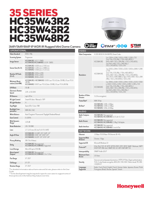
HC35W43R2: Video motion detection,Recording notification HC35W45R2/HC35W48R2: Video motion detection, Alarm input, Recording notification, Tampering
HC35W48R2
1st: 3840 x 2160 / 2592 x 1944 / 2592 x 1520 / 2560 x 1440 / 2304 x 1296 / 1920 x 1080 / 1280 x 720 2nd: 704 x 576 (PAL) / 704 x 480 (NTSC) / 640 x 480 / 352 x 288 (PAL) / 352 x 240 (NTSC) 3rd: 640 x 480 / 352 x 288 (PAL) / 352 x 240 (NTSC) / 320 x 240
Immunity
CE(EN 50130-4), Complies with RCM and UKCA
Safety
UL LISTED TO UL/CSA 62368-1, CE(EN 62368-1), Complies with RCM and UKCA
RoHs
CE(EN 63000), UAE(Cabinet Decree No.10 of 2017)
Number Of Pixels (H x V)
HC35W43R2: 2304 x 1296 HC35W45R2: 2592 x 1944 HC35W48R2: 3840 x 2160
Resolution
Minimum Illumination (Color/BW)
海视感知DS-2DE7A812MCG-EB 8 MP 12 × IR网络速度球机说明说明书

DS-2DE7A812MCG-EB8 MP 12 × Network Speed DomeHikvision DS-2DE7A812MCG-EB 8 MP 12 × IR Network Speed Dome adopts 1/1.8" progressive scan CMOS chip. With the 12 × optical zoom lens, the camera offers more details over expansive areas. This series of cameras can be widely used for wide ranges of high-definition, such as the rivers, roads, railways, airports, squares, parks, scenic spots, and venues, etc. Empowered by deep learning algorithms, Hikvision AcuSense technology brings human and vehicle targets classification alarms to front- and back-end devices. The system focuses on human and vehicle targets, vastly improving alarm efficiency and effectiveness.⏹24/7 colorful imaging⏹High quality imaging with 8 MP resolution⏹12 × optical zoom and 64 × digital zoom provide close up views over expansive areas⏹Audio visual alarm: The white flashing light and audible warning can be triggered by certain events⏹Expansive night view with up to 150 m IR distance and 100 m white light⏹Focuses on human and vehicle targets classification based on deep learning⏹Face capture: Up to 5 faces captured at the same time⏹DORIThe DORI (detect, observe, recognize, identify) distance gives the general idea of the camera ability to distinguish persons or objects within its field of view. It is calculated based on the camera sensor specification and the criteria given by EN 62676-4: 2015.DORI Detect Observe Recognize IdentifyDefinition25 px/m63 px/m125 px/m250 px/m Distance (Tele)1080.0 m (3543.3 ft) 428.6 m (1406.2 ft) 216.0 m (708.7 ft) 108.0 m (354.3 ft)⏹SpecificationCameraImage Sensor 1/1.8" progressive scan CMOSMax. Resolution 3840 × 2160Min. Illumination Color:0.0005Lux @ (F1.2, AGC ON), B/W:0.0001Lux @ (F1.2, AGC ON), 0 lux with light Shutter Speed 1/1 s to 1/30000 sSlow Shutter YesDay &Night IR cut filterZoom 12 × optical, 64 × digitalLensFocal Length 6.7 mm to 80.4 mmZoom Speed Approx. 5.8 sFOV Horizontal field of view: 53° to 8.1° (wide-tele), Vertical field of view: 31.3° to 4.6° (wide-tele), Diagonal field of view:59.6° to 9.3° (wide-tele)Aperture Max. F1.2Focus Auto, semi-auto, manual IlluminatorSupplement Light Type Hybrid (IR and White Light)Supplement Light Range White light: up to 100 m IR: up to 150 mPTZMovement Range (Pan) 360°Movement Range (Tilt) -15° to 90° (auto flip)Pan Speed Pan speed: configurable from 0.1° to 160°/s; preset speed: 240°/s Tilt Speed Tilt speed: configurable from 0.1° to 120°/s, preset speed 200°/s Proportional Pan YesPresets 300Patrol Scan 8 patrols, up to 32 presets for each patrolPattern Scan 4 pattern scansPower-off Memory YesPark Action Preset, pattern scan, auto scan, tilt scan, random scan, frame scan, panorama scan, patrol scan3D Positioning Yes PTZ Status Display YesPreset Freezing YesScheduled Task Preset, pattern scan, patrol scan, auto scan, tilt scan, random scan, frame scan, panorama scan, dome reboot, dome adjust, aux outputVideoMain Stream 50 Hz: 25 fps (3840 × 2160, 2560 × 1440, 1920 × 1080, 1280 × 960, 1280 × 720);60 Hz: 24 fps (3840 × 2160, 2560 × 1440, 1920 × 1080, 1280 × 960, 1280 × 720)Sub-Stream 50 Hz: 25 fps (704 × 576, 640 × 480, 352 × 288);60 Hz: 24 fps (704 × 480, 640 × 480, 352 × 240)Third Stream 50 Hz: 25 fps (1920 × 1080, 1280 × 960, 1280 × 720, 704 × 576, 640 × 480, 352 × 288);60 Hz: 24 fps (1920 × 1080, 1280 × 960, 1280 × 720, 704 × 480, 640 × 480, 352 × 240)Video Compression Main stream: H.265+/H.265/H.264+/H.264 Sub-stream: H.265/H.264/MJPEGThird stream: H.265/H.264/MJPEGVideo Bit Rate 32 kbps to 16384 kbpsH.264 Type Baseline Profile/Main Profile/High ProfileH.265 Type Main ProfileScalable Video Coding (SVC) H.264 and H.265 encodingRegion of Interest (ROI) 8 fixed regions for each streamAudioAudio Compression G.711alaw, G.711ulaw, G.722.1, G.726, MP2L2, AAC-LC, PCMAudio Bit Rate 64 Kbps (G.711)/16 Kbps (G.722.1)/16 Kbps (G.726)/32-192 Kbps (MP2L2)/16-64 Kbps (AAC-LC)Audio Sampling Rate 8 kHz/16 kHz/32 kHz/48 kHzEnvironment Noise Filtering YesNetworkNetwork Storage NAS (NFS, SMB/CIFS), auto network replenishment (ANR)Protocols IPv4/IPv6, HTTP, HTTPS, 802.1x, QoS, FTP, SMTP, UPnP, SNMP, DNS, DDNS, NTP, RTSP, RTCP, RTP, TCP/IP, UDP, IGMP, ICMP, DHCP, PPPoE, Bonjour,WebSocket, WebSocketsAPI Open Network Video Interface (Version 19.12, Profile S, Profile G, Profile T), ISAPI, SDK, ISUPSimultaneous Live View Up to 20 channelsUser/Host Up to 32 users, 3 user levels: administrator, operator, and userSecurity Password protection, complicated password, HTTPS encryption, 802.1X authentication (EAP-TLS, EAP-LEAP, EAP-MD5), watermark, IP address filter, basic and digest authentication for HTTP/HTTPS, RTP/RTSP over HTTPS, control timeout settings, security audit log, TLS 1.2, TLS 1.3, host authentication (MAC address)Client iVMS-4200, HikCentral Pro, Hik-Connect Web Browser IE11, Chrome 57+, Firefox 52+, Safari 11+ ImageDay/Night Switch Day, Night, Auto, ScheduleImage Enhancement BLC, HLC, 3D DNRWide Dynamic Range (WDR) 120 dBDefog Digital defogImage Stabilization EISRegional Exposure YesRegional Focus YesImage Settings Saturation, brightness, contrast, sharpness, gain, and white balance adjustable by client software or web browserPrivacy Mask 24 programmable polygon privacy masks, mask color or mosaic configurable SNR >52 dBInterfaceEthernet Interface 1 RJ45 10M/100M self-adaptive Ethernet portOn-board Storage Built-in memory card slot, support microSD/SDHC/SDXC card, up to 256 GB Alarm 2 inputs, 1 outputAudio 1 input (line in), max. input amplitude: 2-2.4 vpp, input impedance: 1 kΩ ± 10%; 1 output (line out), line level, output impedance: 600 ΩReset YesBuilt-in Speaker 1 built-in speaker with effective distance reaching max. 30 metersEventBasic Event Motion detection, video tampering alarm, exception, alarm input and outputSmart Event Line crossing detection, intrusion detection, region entrance detection, region exiting detection, unattended baggage detection, object removal detection, audio exception detectionSmart Tracking Manual tracking, auto-trackingAlarm Linkage Upload to FTP/NAS/memory card, notify surveillance center, send email, trigger alarm output, trigger recording, audible warning, white light flashing, and PTZ actions (such as preset, patrol scan, pattern scan)Deep Learning FunctionFace Capture Detects up to 5 faces simultaneously.Supports detecting, capturing, grading, selecting of face in motion, and output the best face picture of the facePerimeter Protection Line crossing, intrusion, region entrance, region exitingSupport alarm triggering by specified target types (human and vehicle)GeneralPower 24 VAC, max. 42 W (including max. 12 W for IR and max. 2 W for heater) Hi-PoEOperating Condition -30 °C to 65 °C (-22 °F to 149 °F). Humidity 90% or less (non-condensing) Demist YesMaterial ADC12Dimension Ø 220 mm × 357.3 mm (Ø8.66" × 14.07")Weight Approx. 5.5 kg (12.13 lb.)ApprovalProtection IP66 (IEC 60529-2013), IK10 (excluding glass window), TVS 6000V lightning protection, surge protection and voltage transient protectionEMC UL (UL 62368-1); CB (IEC 60950-1:2005 + Am 1:2009 + Am 2:2013); CE-LVD (EN 62368-1:2014+A11:2017); BIS (IS 13252 (Part 1):2010+A1:2013+A2:2015); LOA (IEC/EN 60950-1)Safety UL (UL 62368-1); CB (IEC 60950-1:2005 + Am 1:2009 + Am 2:2013); CE-LVD (EN 62368-1:2014+A11:2017); BIS (IS 13252 (Part 1):2010+A1:2013+A2:2015); LOA (IEC/EN 60950-1)Environment CE-RoHS (2011/65/EU); WEEE (2012/19/EU); Reach (Regulation (EC) No 1907/2006)⏹Dimension⏹Accessory⏹IncludedDS-1602ZJ Wall mount⏹Optional⏹Available Model DS-2DE7A812MCG-EBDS-1667ZJ Pendant Mount DS-1604ZJ-BOX-CORNERWall Mount withJunction BoxDS-1604ZJ-BOX-POLEPole MountDS-1681ZJDS-1681ZJDS-1682ZJDS-1682ZJDS-1681ZJ-2 Installation AdapterDS-1660ZJParapet WallMountDS-1662ZJPendant MountDS-1663ZJCeiling MountDS-1604ZJ-boxWall MountDS-1604ZJ Wall MountDS-1673ZJVertical PoleMountDS-1619ZJPendant MountDS-1661ZJPendant Mount。
海康威视 4K 超低光线 VF 弹簧相机说明书

Key Features● 8.29 MP high performance CMOS● Ultra-low light● 3840 × 2160 resolution● Auto focus, 2.8 mm to 12 mm motorized vari-focal lens ● 120 dB true WDR, 3D DNR● EXIR 2.0, smart IR, up to 80 m IR distance● Dual video output: TVI/CVBS● Dual voltage input: 12 VDC ±25%/24 VAC ±25%● IP67● Up the coax (HIKVISION-C)CameraImage Sensor 8.29 megapixel progressive scan CMOS Signal System PAL/NTSCFrame Rate PAL:***********,5MP@20fps,4MP@25fps,1080p@25fps NTSC: 8 MP@15fps, 5 MP@20fps, 4 MP@30fps, 1080p@30fpsResolution 3840 (H) × 2160 (V)Min. illumination Color: 0.003 Lux@(F1.2 AGC ON), 0 Lux with IRShutter Time PAL: 1/12.5 s to 1/10,000 s NTSC: 1/15 s to 1/10,000 sSlow Shutter Max. 16 timesLens 2.8 mm to 12 mm motorized vari-focal lensHorizontal Field of View 108.1° to 45.6°Lens Mount Φ14Day & Night IR cut filterAngle Adjustment Pan: 0° to 360°, Tilt:0° to 90°, Rotate: 0° to 360°Synchronization Internal synchronizationWDR (Wide Dynamic Range) 120 dBMenuAGC SupportDay/Night Mode Auto/Color/BW (Black and White)White Balance Auto/Manual/NaturalPrivacy Mask ON/OFF, 4 programmable privacy masksBLC (Backlight Compensation) Support3D DNR (Digital Noise Reduction) Level 1 to 10Language EnglishFunctions Contrast, Sharpness, Saturation, Mirror, Defog, HLCInterfaceTVI Video Output 1 HD analog outputCVBS Video Output 1 CVBS output (75Ω/BNC)GeneralOperating Conditions -40 °C to 60 °C (-40 °F to 140 °F), humidity: 90% or less (non-condensation)Power Supply 12 VDC ±25%-A: 12 VDC ±25%, 24 VAC ±25%*You are recommended to use one power adapter to supply the power for one camera.Power Consumption Max.11.5 W-A: Max. 14.5 WIngress Protection IP67Material MetalIR Range Up to 80 mCommunication Up the coax, Protocol: HIKVISION-C (TVI output) Dimensions 92 mm × 89 mm × 269.6 mm (3.62" × 3.5" × 3.34") Weight Approx. 955 g (2.11 lb.)SpecificationOrder ModelsDS-2CE19U8T-IT3Z; DS-2CE19U8T-AIT3ZDimension 92 mm (3.6")89 mm (3.5")269.6 mm (10.6")155.6 mm (6.2")241.3 mm (9.5")3-Ø 4.3 mm(0.17")120° 3 × 10-24UNC-2AØ 85.3 mm(3.36")Ø 70 mm(2.76")AccessoryDS-1280ZJ-S Junction Box DS-1275ZJ-SUS Vertical Pole MountDS-1H18 Video Balun010*********。
汉睿公司的2.0 MP IR网络长杠相机产品介绍说明书

Key Features• 1/2.8" progressive scan CMOS • 3D DNR (Digital Noise Reduction) • 1920 × 1080@30fps• Up to 30 m IR range • 2.8 mm/4 mm/6 mm fixed lens • PoE (Power over Ethernet) • H.265+, H.265, H.264+, H.264 •IP67• Dual stream•Digital WDR (Wide Dynamic Range)CameraImage Sensor 1/2.8" progressive scan CMOSMin. Illumination Color: 0.01 Lux @(F1.2, AGC ON), 0.028Lux @ (F2.0, AGC ON) Shutter Speed 1/3 s to 1/100, 000 sSlow Shutter YesAuto-Iris NoDay &Night IR cut filterDigital Noise Reduction 3D DNRWDR Digital WDRAngle Adjustment (Bracket) Pan: 0° to 360°, tilt: 0° to 180°, rotation: 0° to 360°LensFocal length 2.8 mm, 4 mm, 6 mmAperture F2.0Focus NoFOV 2.8 mm, horizontal FOV 103°, vertical FOV 59°, diagonal FOV 118°4 mm, horizontal FOV 86°, vertical FOV 46°, diagonal FOV 102°6 mm, horizontal FOV 54°, vertical FOV 30°, diagonal FOV 62°Lens Mount M12IRIR Range Up to 30 m Wavelength 850 nm Compression StandardVideo Compression Main stream: H.265/H.264Sub stream: H.265/H.264/MJPEGH.264 Type Baseline Profile/Main Profile/High Profile H.264+ Main stream supportsH.265 Type Main ProfileH.265+ Main stream supportsVideo Bit Rate 32 Kbps to 8 MbpsSmart Feature-setRegion of Interest 1 fixed region for main stream and sub-stream ImageMax. Resolution 1920 × 1080Main Stream Max. Frame Rate 50Hz: 25fps (1920 × 1080, 1280 × 960, 1280 × 720) 60Hz: 30fps (1920 × 1080, 1280 × 960, 1280 × 720)Sub-stream Max. Frame Rate 50Hz: 25fps (640 × 480, 640 × 360, 320 × 240) 60Hz: 30fps (640 × 480, 640 × 360, 320 × 240)Image Enhancement BLC, 3D DNRImage Setting Saturation, brightness, contrast, sharpness, AGC, white balance adjustable by client software orweb browserDay/Night Switch Auto, scheduledNetworkAlarm Trigger Motion detection, video tampering alarm, illegal loginProtocols TCP/IP, ICMP, HTTP, HTTPS, FTP, DHCP, DNS, DDNS, RTP, RTSP, RTCP, NTP, UPnP, SMTP, IGMP,802.1X, QoS, IPv6, UDP, BonjourGeneral Function Anti-flicker, heartbeat, mirror, password protection, privacy mask, watermarkFirmware Version 5.5.2SpecificationAvailable ModelsIPC-B120H (2.8/4/6 mm), IPC-B120H-M (2.8/4 mm)APIONVIF (PROFILE S, PROFILE G), ISAPI Simultaneous Live View Up to 6 channelsUser/Host Up to 32 users3 levels: Administrator, Operator, and User Client HiLookVision PC Client, HiLookVision AppWeb Browser IE8+, Chrome 41.0-44, Firefox 30.0-51, Safari 8.0-11InterfaceCommunication Interface1 RJ45 10M/100M self-adaptive Ethernet portGeneralOperating Conditions -30 °C to 50 °C (-22 °F to 122 °F), humidity: 95% or less (non-condensing) Power Supply12 VDC ± 25%, 5.5 mm coaxial power plug PoE (802.3af, class 3)Power Consumption and Current 12 VDC, 0.4 A, Max: 5 WPoE: (802.3af, 36 V to 57 V), 0.2 A to 0.13 A, Max: 7 W Protection LevelIP67MaterialWithout –M model:Front cover: metal, camera body: plastic, bracket: plastic -M model:Front cover: metal, camera body: metal, bracket: metal DimensionsCamera: Ø 70 mm × 191.3mm (Ø 2.7" × 7.5")With package: 216 mm × 121 mm × 118 mm (8.5" × 4.8" × 4.6") WeightWithout –M model:Camera: Approx. 280 g (0.6 lb.)With package: Approx. 530 g (1.2 lb.) -M model:Camera: Approx. 395 g (0.9 lb.)With package: Approx. 631 g (1.4 lb.)Dimensions191.3 mm (7.53" )66.7 m m (2.63 " )(2.76 " )120°AccessoryHIA-J101 Junction Box。
SNV-5084RN P 1 3英寸3.09M CMOS视频影像设备说明书

Intelligent Video Analytics Alarm I/O Alarm Triggers
Tampering, Virtual line, Enter / Exit, (Dis)Appear, Audio detection, Face detection with metadata
Input 1ea / Output 1ea
Alarm Events Network
File upload via FTP and E-mail, Notification via E-mail, TCP Local storage (SD/SDHC/SDXC) recording at Network disconnected & Event (Alarm triggers), External output
Motion detection, Tampering, Audio detection, Face detection, Video analytics, Network disconnection, Alarm input
• Simple focus, P-Iris, Enhanced DIS, Defog • Multi-crop streaming
Audio Out
Line out (3.5mm mono jack), Max output level : 1 Vrms
Audio Compression Format
G.711 u-law/G.726 selectable, G.726 (ADPCM) 8KHz, G.711 8KHz G.726 : 16Kbps, 24Kbps, 32Kbps, 40Kbps
B/W : 0Lux (IR LED on)
园区监控方案

园区监控方案系统的设计应该具有可扩展性,能够随着园区规模的扩大和监控需求的增加而不断扩展。
系统应该具有开放性和兼容性,能够与其他设备和系统进行互联互通,方便后期的升级和扩展。
二、系统设计依据本系统的设计依据是园区的实际情况和监控需求,结合国内外先进技术和标准,采用数字视频监控技术,实现对园区内各个区域的实时监控和管理。
三、系统总体架构设计本系统采用分布式架构,由前端设备、网络传输、后台存储和管理四个部分组成。
前端设备包括网络摄像机和解码器,网络传输采用高速网络,后台存储和管理采用专业的存储设备和软件。
四、系统组网拓扑本系统采用星型拓扑结构,每个网络摄像机都与核心交换机相连,核心交换机再与存储设备相连。
这种拓扑结构具有稳定性和可靠性,同时也方便后期的扩展和升级。
五、系统存储特点本系统采用专业的存储设备和软件,具有高效、稳定、安全、可靠的特点。
存储设备采用RAID技术,能够保证数据的安全性和可靠性。
软件采用专业的存储管理系统,能够实现对存储设备的统一管理和监控。
六、摄像机产品介绍本系统采用的摄像机产品有网络枪机DS-2CD2T10D-I3、网络半球DS-2CD2310D-I和网络球机DS-2DM7120I-A。
这些产品具有高清晰度、低光照、远距离监控等特点,能够满足园区监控的需求。
可扩展性原则是指系统在横向和纵向方向上都具备扩展能力。
在横向扩展方面,智能视频监控系统应该能够方便地扩展容量,以满足更大规模的视频监控需求。
在纵向扩展方面,视频监控系统应该具备良好的兼容性和通用的软硬件接口,使用户可以进行二次功能开发,例如图像智能分析等。
随着系统的扩展,用户容量将会不断扩大,新的业务功能的要求也会层出不穷。
因此,在系统建设的初期,应该以近期的应用需求为基础进行系统配置,并考虑系统的可扩展性,以保证未来3~5年内的发展需求。
安全保密性原则也非常重要,特别是对商业场所的实时监控和数据传输量大的情况下。
除了考虑各种外界干扰外,还需要在各个环节提供安全、保密措施。
HD-TVI 1080p 2MP 强光红外球形摄像机 Wall Ceiling 挂载说明书

INTCM1(Pole/Corner Mount)DIMENSIONSFEATURESSPECIFICATIONSImage Sensor.................. 1/2.9” Progressive Scan CMOS, 2MPMinimum Illumination....... 0.00 lux (IR LED on)Effective Pixels................ 1984 (H) x 1105 (V) Total Pixels...................... 2000 (H) x 1121 (V) Scanning System............ Progressive S/N Ratio......................... More than 50dB Output Resolution............ 1920x1080 @ 30fps Video Output.................... 1.0Vp-p / 75 OhmsElectronic Shutter............ Auto / Manual (1/30 –1/30,000 sec.) Day / Night....................... Auto / Color / BW / External Test Monitor Output......... CVBS (BNC out in Yellow)Communication............... UTC (up the coax) Power............................. 12VDC / 24VACPower Consumption........ 900mA max. (DC), 750mA max. (AC) Operating Temperature.... -4°F –122°FUnit Dimensions.............. 9.64” (L) x 3.72” (Dia.)Unit Weight...................... 2lbs (camera), 0.9lbs (junction box)Certifications.................... FCC, RoHS Signal Distance............... Up to 1600 feet(depending on coax quality)*• Full HD resolution over coax (HD-TVI) • Supports up to Full HD 1080p @ 30fps • True WDR operation• Intense IR function –no saturation, IR intensity adapts to subject to provide vivid image• Built-in heater and anti-fog glass reduces condensation • 3-axis for wall and ceiling mounting• Full OSD operation through on-board control and UTC (up the coax) • Additional 960H analog output • Signal distance up to 1600 feet* • IP67 compliant, weather resistant • 12VDC & 24VAC dual voltage operation • 5 year warrantyOSD MENU TREECameraOptional AccessoriesUnit : inchMAIN SETUP EXPOSURE •B/W•EXTERN•LOW•MIDDLE•HIGH•SHARPNESS •GAMMA •MIRROR•FLIPDAY / NIGHTCOLOR SPECO DNR IMAGE EXIT•BRIGHTNESS•SHUTTERBACKLIGHT •HLC •BLC •WDR •AUTO•AWB •COLOR GAIN •ACE •DEFOGSYSTEM •OUTPUT •FREQ.•IMAGE RANGE•INTENSIFY•AGC•COLOR IRIS MOTION•FRAME RATE•LANGUAGE •COLOR BAR •RESET•CAM TITLE •PRIVACY 2-MOTOR •COLOR SPACE •COM.Junction Box includedOSD JoystickVideo Test (CVBS)Right (Near)Up (Zoom-In)Down (Zoom-Out)Left (Far)OSD CONTROLOSD MENU DetailsDAY / NIGHT : Adjust Day / Night options .COLOR : Always Color mode, Default value for these cameras B/W : Always B/W mode.-ANTI-SAT. : Adjusts the Anti Saturation level (0~20)EXT : This mode allows you to apply a desired filter to external signals. -ANTI-SAT. : Adjusts the Anti Saturation level (0~20)-EXTERN S/W : Selected at manufacturer side-D →N LEVEL (0~20) : Selected at manufacturer side -N →D LEVEL (0~20) : Selected at manufacturer side-DELAY : Adjusts the changing delay time (LOW/MIDDLE/HIGH) AUTO : this mode is not available for this camera COLOR : Adjusts white balancing options.AWB : it goes to optimized color level automatically.COLOR GAIN : Sets the desired Color Gain value (0~20)SPECO DNR : Uses to reduce the background noise in a low luminanceenvironment with 2D + 3D filtering system.BACKLIGHT : Adjusts backlight options.WDR : WDR illuminates darker areas of an image while retaining thesame light level for brighter areas to even out the overall brightness of images with high contrast between bright and dark area -Adjusts the WDR Weight (LOW/MIDDLE/HIGH)* CVBS out cannot adjust this function.BLC : Produces a clearer image of an object darkened by strong backlighting.-H-POS : Adjusts the horizontal position(0~20)-V-POS : Adjusts the Vertical position(0~20)-H-SIZE : Adjusts the horizontal block size (0~20)-V-SIZE : Adjusts the vertical block size (0~20)HLC : Uses to contain extremely bright areas such as from car headlight,the light can be masked out much of the on-screen details.IMAGE : Adjusts various image options.SHARPNESS: Adjusts sharpness level. Increasing this value, the pictureoutline becomes stronger and clear. (0~10)GAMMA : Sets the desired Gamma value. (0.45 ~ 0.75)MIRROR : Change the video direction horizontally.FLIP:Change the video direction perpendicularly.ACE (D-WDR) : Uses a digital wide dynamic range to balance dark and oversaturated areas within the image.DEFOG : Activated this mode when the video or the weather is foggy.PRIVACY : Used to hide regions of the image.MOTION : Adjust motion detection settings. DET WINDOW DET TONE MDRECT FILLSENSITIVITY : Sets the desired of “Motion” (0~20)MOTION OSD TEXT ALARM SIGNAL OUTIRIS : ‘ALC’ as a default value2-MOTOR : AF Mode, Scanning, OnepushAF, Sync TDN, Initial EXPOSURE : adjusts exposure settings.BRIGHTNESS : Adjusts image brightness. (0~ 20)SHUTTER : Outdoor / Indoor / DeblurINTENSIFY : Sets the desired multiple of the digital exposure length.AGC(Auto Gain Control): Adjusts the AGC level. (0~10)Speco Technologies is constantly developing product improvements. We reserve the right to modify product design and specifications without notice and without incurring any obligation.Rev. 220415SYSTEM : Adjusts various camera system options.OUTPUTMAIN OUTPUT ANALOG OUT0ANALOG OUT0 TVI Y GAIN CB GAIN CR GAIN POSITION BURST FREQ BURST GAIN B&WUCC SELECT 720EXFRAME RATE: 1080P 30 / 720P 60FREQ 60Hz COM.IMAGE RANGE COLOR SPACECOLOR BAR : Manufacturer’s optionLANGUAGE : Sets the desired OSD language CAM TITLERESET: Press with long to reset all settings to factory defaults.。
- 1、下载文档前请自行甄别文档内容的完整性,平台不提供额外的编辑、内容补充、找答案等附加服务。
- 2、"仅部分预览"的文档,不可在线预览部分如存在完整性等问题,可反馈申请退款(可完整预览的文档不适用该条件!)。
- 3、如文档侵犯您的权益,请联系客服反馈,我们会尽快为您处理(人工客服工作时间:9:00-18:30)。
A12-mW Wide Dynamic Range CMOS Front-End for a Portable GPS Receiver Arvin R.Shahani,Derek K.Shaeffer,Student Member,IEEE,and Thomas H.Lee,Member,IEEEAbstract—This paper describes a CMOS low-noise amplifier (LNA)and mixer intended for use in the front-end of a global positioning system(GPS)receiver.The circuits were implemented in a standard0.35- m(drawn)CMOS process,with one poly and two metal layers.The LNA has a forward gain(S21)of17dB and a noisefigure of3.8dB.The mixer has a voltage conversion gain of03.6dB and a third-order intermodulation intercept point (IP3)of10dBm,input referred.The combination draws12mW from a1.5-V supply.Index Terms—Amplifier noise,CMOS analog integrated cir-cuits,Global Positioning System,low-noise amplifiers,mixers, receivers.I.I NTRODUCTIONT HERE is large enthusiasm in the consumer market for the capabilities of the Global Positioning System(GPS). Manufacturers of cellular telephones,portable computers,and other mobile devices are looking for ways to incorporate GPS into their products.For many of these hand-held devices,one of the primary concerns is battery life.Thus,there is strong motivation to provide good performance at very low power. The viability of a CMOS low-noise amplifier(LNA)within the context of GPS has been demonstrated previously[1]. This paper extends that work to include the mixer and also investigates a differential LNA architecture.The decision for a differential LNA was made to avoid problems caused by substrate coupling in a single-ended design.Section II applies the results of[1]to this paper’s LNA, in addition to discussing the current LNA’s salient features. Section III details the mixer design and addresses the topics of conversion gain,linearity,and noise.Experimental results are presented in Section IV,followed by the authors’conclusions in Section V.II.LNAA.LNA DescriptionFig.1shows a circuit-level description of the LNA.A differential architecture was selected for better rejection of on-chip interference.The penalty for such a decision is that twice the power must be consumed to achieve the same noisefigure as a single-ended version.Manuscript received June30,1997;revised August18,1997.This work was supported by Defense Advanced Research Projects Agency(DARPA)under Contract N65326-96-C-8608and IBM under the IBM Fellowship program. The authors are with the Center for Integrated Systems,Stanford University, Stanford,CA94305-4070USA.Publisher Item Identifier S0018-9200(97)08269-3.Fig.1.LNA circuit diagram.The LNA consists of two stages:the input stage,formed bytransistorson the LNA’s input impedance.Specifically,the Miller effect tends to substantially lower the input impedance,complicating the task of matching to the input.In addition to mitigating the Miller effect,the use of a cascode improves the LNA’s reverse isolation,which is important in the present application for suppressing local oscillator(LO)feedthrough from the mixer back to the LNA’s RF input.Furthermore,because the output of thefirst stage is tuned with spiralinductors,.It should be noted,however,that a noise penalty is incurred when using a cascode.But,with proper attention to the layout of the devices,the additional noise can be minimized,as discussed in the following section.As shown in Fig.2,the LNA must present the proper input impedance to terminate the off-chip RFfilter preceding it.For this purpose,inductive degeneration is employed in the sourcesofFig.2.Block diagram of the receiverfront-end.Fig.3.Single-ended version of the dc biasing technique.goal is to use theminimumlevel.This fraction becomes thereference to which the input devices’common-modethroughis the differential input resistanceand,because gain will bemaximized by doing so.Loss of signal energy,from mistuning or excessively narrow bandwidths,is not an issue,sincetheis the device’s zero-bias drain conductance,andare coefficients describing the magnitude of the noise powers.In addition to these noise sources,the epitaxial layer’s resistance may contribute noise through the body effect.Such epi noise can be accounted for by slightlyincreasingSHAHANI et al.:DYNAMIC RANGE CMOS FRONT-END2063(a)(b)Fig.5.Mixer circuit diagram.(a)Mixer with probe buffer and (b)mixer circuit used in analysis.figure for a specified power consumption and input impedance.Note that this optimum exists because the gate noise and drain noise terms are not fully correlated.Fig.4plots noise figure as a function of input device width and clearly shows an optimum width of about500m because the detailednature of the gate noise was unknown to the authors when this amplifier was designed.However,the curve has a broad minimum,so the achievable noise figure is little affected by using transistors of this width,at least in principle.The discrepancy between the theoretical minimum of 1.8dB and the measured noise figure of 3.8dB will be addressed in Section IV.III.M IXERA.Mixer DescriptionThe mixer consists of the fourtransistors,-match and an RF tank.The-match is to boost the signal voltageacross the mixer’s RF port via an impedance transformation,while the RF tank is used to filter broad-band noise at the RF port of the mixer.As will be discussed later,this filtering is important because multiple frequencies at the mixer’s RF port are converted to the intermediate frequency at the mixer’s IF port.B.Mixer Conversion GainFig.5(b)shows a simplified mixer circuit that is used in the following analysis.1)Definition:The voltage conversion gain for this mixer is found by exciting the circuit with a RFsinusoid,.Therefore,incalculatingit will be assumedthat,which in the frequency domainis-match.This sequence of reductions is depicted inFig.6(b)and (c),respectively.From those simplifications,it is clearthat.Note that ifthe5pF,it is small.Still,the load capacitance,together with the conductance of the switches,has someeffecton.However,the error inassumingintroduces2064IEEE JOURNAL OF SOLID-STATE CIRCUITS,VOL.32,NO.12,DECEMBER1997(a)(b)(c)Fig.6.Illustration of passive network reduction at resonance.(a)Unreduced network,(b)RF tank reduced,and (c)L -match reduced.3)LO Signals:Before proceeding further,it is relevant to discuss how the mixer is driven,specifically the shapes of the LO and LO waveforms.LO is simply a time-shifted version of LObyis the rectangle function.This LO signal will be thereference to which other types of LO signals will be compared,and it is sketched in Fig.7(a).In practice,a square wave drive is difficult to achieve.A more practical and power-efficient method is to resonate the gate capacitances and drive the gatessinusoidally(7)whereis the dc level on the gates.This type of wave-form is drawn in Fig.7(b)–(d)for three choicesof.In Fig.7(b),equals the switch thresholdvoltage illustrating break-before-make switchingaction;while in Fig.7(d),which is the opposite action,make-before-break.4)Mixer’s Th´e venin Equivalent:The switches in the mixer are just time varying conductances,as shown in Fig.8(a).Therefore,it is possible to simplify the switch network with a Th´e venin equivalent network,generatedfrom(8)and the Th´e venin impedance,written as a conductance,isis a mixed versionof.Fig.9illustrates themixingfunction(10)and,for the four cases.Bothexhibit important properties.The mixingfunction,and has half wave symmetry,implying thatit only has odd frequency content(,where has a dc component and isperiodic with aperiod.To findthe conversion gain from the RF port to the IF port,the Fourier transform of the mixing function must be evaluatedat,which has been done in Table I.It is interesting to notethatSHAHANI et al.:DYNAMIC RANGE CMOS FRONT-END2065(a)(b)Fig.8.Mixer core.(a)Time varying conductances and (b)Th´e venin equiv-alent.(a)(b)(c)(d)Fig.9.Mixing function and Th´e venin conductance for the four cases.(a)Square wave drive,(b)sinusoidal drive,(c)break-before-make,and (d)make-before-break.on a single quantity that characterizes an LOwaveform,.Ingeneral,as a functionof ,after findingthe network’s impulse response.The detailed derivations are contained in the Appendix,while key results are presented here.The results indicate that under certain conditions,a very simple system can be used to analyze the core conversion gain.Furthermore,the results also predict that it is theoretically possible to achieve a core conversion gain of one.TABLE Ij M (f LO )jFOR THEF OUR CASES(a)(b)(c)(d)Fig.10.Modified mixing functions for the four cases.(a)Square wave drive,(b)sinusoidal drive,(c)break-before-make,and (d)make-before-break.The following discussion appliesif.For this case,the superpo-sition integral reducesto(11)This equation provides insight into the mixer’s behavior.The RF port’s voltage is evidently multiplied by a modified mixing function,which we will defineasis the peak conductanceof ,normalizingto varybetweenis also introduced tohighlight a gainterm(14)The remaining terms implement a very familiar component.A simple single-pole low-pass filter is shown in Fig.11.The superposition integral,which reduces to a convolution integral,for this caseis(15)2066IEEE JOURNAL OF SOLID-STATE CIRCUITS,VOL.32,NO.12,DECEMBER1997Fig.11.Single-pole low-passfilter.Fig.12.Equivalent block diagram for core conversion gain.By comparing (15)to (14),we see that (14)has the same form as (15),except(16)In words,this equation indicates that the RF port’s voltage is multiplied,gained,and then filtered by a single-pole low-pass filter,as diagrammed in Fig.12.The total voltage conversion gain isjustfor a sine wavewithgives rise to a better conversion gain,by a factoroffor the reference square wave drive.For a sinusoidaldrive,is2.1dB),which exceedsthe3.9dB)value for a square wave drive.Observing that the conversion gain of a sinusoidal drive is better than that for a square wave drive motivates examination of the conversion gain for the specific case of a break-before-make drive.It is possible,though slightly involved,to express conversion gain as a functionof.Fig.13plots (17)as a functionof,contrary to widely heldbeliefs..,linearity suffers,so this drive is not a practicalone.Fig.13.A j M 0(f LO )j versus r for break-before-make.C.Mixer LinearityThere are two major sources of distortion in the mixer:device nonlinearities and phase modulation of the switching instants.To improve the linearity of the transistors,it is most important to keep the current through the switches small to reduce nonlinear voltage drops across the devices [3].This criterion is satisfied with the use of a small capacitive load,which presents a high impedance to the output.The remaining nonlinearities consist of parasitic junction capacitances,which are weak nonlinearities.Furthermore,at the RF port,the parasitic junction capacitances are insignificant compared with the large,linear tankcapacitance.Thusthe frequencies in theset,,whereSHAHANI et al.:DYNAMIC RANGE CMOS FRONT-END2067Fig.14.Diephoto.Fig.15.Block diagram of the GPS front-end test setup.However,making the switches very wide increases their contribution to the load capacitance,which eventually reduces conversion gain.Also,LO power increases as the switches are made wider because a smaller inductance must be used to resonate the gates.For afixedm CMOStechnology with only two metal layers.A die photograph is shown in Fig.14.The aspect ratio of the silicon is somewhat unusual because this project was designed to fit in the scribe lane of a wafer that was primarily devoted to other dice.Accordingly,the dimensions are3502.4mm.Fig.15shows how the die was packaged for testing,and important comments regarding testing follow.First,the inter-face between the LNA and the mixer was taken off-chip to facilitate testing only.By doing so,each block could be tested individually.In a real chip,the LNA would interface on-chip directly to the mixer.Second,the probe buffer,following the mixer,is used to measure the mixer’s output.It was designed so that its linearity does not interfere with the mixer linearity measurement.In a real chip,an IF amplifier would replace the probe buffer,and since test equipment no longer needs to be driven,design of the IF amplifier can proceed withoutTABLE IIGPS F RONT -E ND P ERFORMANCE SUMMARYhaving to drive a50-2068IEEE JOURNAL OF SOLID-STATE CIRCUITS,VOL.32,NO.12,DECEMBER1997Fig.16.Noise figure versus device width for R in =100 andR in =40 .the complete amplifier has more than one noise contributor;however this is not sufficient to account for the discrepancy.A measurement of the input impedance of the LNA revealed the primary reason for the difference.The real part of the input impedance was found to be only40-differential.This gross difference ispartially due to the influence of the overlap capacitance of the input devices,which lowers the impedance seen at the gates of those devices.This behavior was observed in simulations of the LNA’s input impedance,but unfortunately,the impact of the reduced impedance on the noise figure was not fully appreciated at the time.Furthermore,increasing the inductance of the source spiralinductorsm is substantiallyremoved from the optimum point on the40-curve.These compounding effects illustrate thepenalty in undershooting the desired input impedance.The revised prediction anticipates a 3.2-dB noise figure from the input pair alone.Thus,the observed total noise figure of 3.8dB is reasonable,given that other devices in the circuit contribute noise in a second-order fashion.For example,the cascode devices,the load inductors,and the output stage transistors all have noise,which contributes some small amount to the noise figure.The forward gain (S21)and noise figure are plotted in Fig.17.One salient feature of the differential LNA architecture that merits discussion is its reverse gain (S12),which was measured to be less than3.6dB.The measurement wasperformed with the input port of the mixer impedance matched to100--match network,the expected voltage con-version gain should be close to6dB for the voltage attenuation from matching the input port andoftheat resonance,corresponding to a totalnetwork3.5dBm in a100-if the LO were integrated with the mixer.Indeed,a higher impedance could be achieved with spiral inductor tuning of the LO port to further reduce LO power.The single-sideband (SSB)noise figure of the mixer is estimated to be 10dB based on noise figure measurements of the mixer/buffer combination.Given the gain of the preceding LNA,the mixer contributes 0.3dB to the noise figure of the LNA/mixer combination.The IP3of the combination is approximately43dBm.SHAHANI et al.:DYNAMIC RANGE CMOS FRONT-END2069Fig.18.Mixer two-tone IP3measurement.V.C ONCLUSIONA functional LNA/mixer combination for a CMOS GPS receiver has been presented.The LNA’s measured reverse gain (S12)of.To determine the initial voltage producedoncoulombs.This charge producesan initial voltageof Von.T h e n,t h ef o l l o w i ng d i f f e r e n t i a l e q u a t i o n d e s c r i b e s th e ci r c u i t’s r e s p o n s et o t h i s i n i t i a l c o n d i t i o n:(20)w h e r e i s t h e u n i t s t e p f u n c t i o n.F i n a l l y,u s is u p e r p o s i t i o n i n t e g r a l p r o d u c es(21)S o m e u s e f u l m a n i p u l a t i o n s a r e e n a b l e d i fi s w r i t t e n as(22)w h e re.F u r t h e r m o r e,t h e i n t e gof w i l l b e c a l l edi s a n a r b i t r a r y c o n s t a n t.T h e s e m o d ificu s t o w r i te(24)T h i s l a s t r e s u l t w a r r a n t s c l o s e a t t e n t i o n.Ti n v o l v i ng2070IEEE JOURNAL OF SOLID-STATE CIRCUITS,VOL.32,NO.12,DECEMBER1997Arvin R.Shahani received the B.S.and M.S. degrees from Stanford University,Stanford,CA,in 1993and1995,respectively.He is currently pursu-ing the Ph.D.degree at Stanford University where his research focuses on CMOS receiver blocks. During the summers of1992and1993,he worked at Quantum Corporation developingfirmware in the High Capacity Storage Group.During the summer of1995,he worked at IBM’s T.J.Watson Re-search Center designing high frequency oscillators in IBM’s SiGe process.Derek K.Shaeffer(S’90),for a photograph and biography,see p.759of the May1997issue of this J OURNAL.Thomas H.Lee(S’87–M’87),for a photograph and biography,see this issue, p.1857.。