塞普拉斯40亿美元合并飞索 汽车芯片新巨头
IMDS材料数据系统使用指南(10.0版本)

1.4 1.5 1.6 127 日 2013 年 4 月 23 日
2013 年 5 月 24 日 2013 年 6 月 27 日
2013 年 12 月 12 日 2014 年 3 月 17 日 2014 年 7 月 13 日 2015 年 2 月 27 日 2015 年 4 月 27 日 2015 年 6 月 10 日 2015 年 6 月 11 日 2015 年 7 月 10 日
第3页
目录
1 IMDS – 简介.............................................................................................................................................................................................................. 7 2 IMDS – 使用入门 ...................................................................................................................................................................................................... 8
IMDS 服务中心 欧洲 | 电话: +36 1778-9821 | 电子邮件: imds-helpdesk-english@ 中国 | 电话: + 86 27 8743-1668 | 电子邮件: imds-eds-helpdesk-china@
赛普拉斯和飞索完成换股合并

将在未来三年内每年减少 1 . 3 5 亿美元的开支 , 并将 熟 商 用 , 并有 望 在今 年 跻 身全 球 f a b l e s s T o p l 0 ; 浪潮 体现在合并后的第一个完整年度的税后盈利 中。合 研 制 出 了国 内第 一代 主机 系统 , 并成 功在 行业应 用 ; 并后的公 司仍将 向股东支付每股 0 . 1 1 美元 的季度 曙光公司推 出国内首款基于龙芯 3 B处理器的服务
近 日, 武岳峰资本宣布与芯成半导体 ( I S S I ) 达
成收购协议 , 以每 股 1 9 . 2 5美 元 , 总 价格 约 6 . 3 9 5亿
M T 3 1 8 8 已正式对客户供货。包括电源电子、 监测电 路及共振器在 内的参考设计 已通过无线充 电标准
A l l i a n c e f o r Wi r e l e s s P o w e r( A 4 WP) 、 Wi r e l e s s P o w e r C o n s o r t i u m( WP C) 和 P o w e r Ma t t e r s A l l i a n c e ( P MA)
- ● ● n. I l 1 . ^ - ^ - |, 、 ; ^m ^…
一
L 一 业 界 要闻
斯 的股 东批 准 了发 行新 股 ,并 以 2 . 4 5 7 : 1的 比例换 购 飞索 全部股 票 的提案 。飞 索 的股 东在 另一 场会 议 中批 准 了该合 并 案 。此项 合并 产生 的协 同效 应 预计
定携手共同开拓工业 4 . 0中国与全球市场 ,深入开
展技术合作与联合创新 , 打造开放 、 健壮与安全的工
业4 . 0 I C T ( 信息和通信技术 ) 平台 。该项共同决定 疗监控 、 电子测量 、 照明设备以及功耗与汽车控制器
赛普拉斯汽车市场再度发力,TraveoⅡMCU来了.

汽车的电动化、网联化、智能化、共享化,这颠覆性的四大趋势正推动着汽车产业新剧变,将会为人类的出行和社会的发展带来翻天覆地的变化。
EVsales 数据显示,2018年全球新能源乘用车销量突破200万辆,相比去年提高了一倍左右。
另外,自动驾驶实现L5级,让驾驶员释放双手,也是各家争抢的大饼。
但目前来看,业内基本还在普及L2级自动驾驶技术,L3级仅有极少数车型,真正在做L4-L5级自动驾驶测试的仅几家而已,距商用落地还需要一段路程要走。
这里面临最大的问题是安全性,包括功能性安全、信息数据的安全。
不仅如此,面对越来越多的ECU 、爆炸性扩增的软件内容、不断增长的连接需求,汽车电子该如何应对以上带来的挑战。
普拉斯半导体汽车电子事业部亚太区市场总监文君培供应商一致认为,若想在这个竞争激烈的领域谋求发展必须要有改变。
MCU 作为汽车电子系统内部运算和处理的核心,遍布在多个子系统中,特别是在自动驾驶技术上。
智能系统需要MCU 进行运算、安全通信和数据处理,因此对MCU 有着苛刻的要求,无论是在安全、性能、扩展性、升级、连接,还是在功耗方面都要有出色的表现。
嵌入式解决方案供应商赛普拉斯(Cypress )半导体公司近日宣布推出其专门针对车身电子全新的Traveo II MCU 。
拥有先进的功能和一流的高能效处理能力,覆盖从低端到高端各种汽车应用。
普拉斯半导体汽车电子事业部亚太区市场总监文君培先生在发布会上详细介绍了Traveo II MCU 的相关信息。
Traveo II 的几大特点Traveo II 相较Traveo 有什么提升呢?文先生从以下几点分别做了解释。
高度的可扩展性:Traveo II 针对不同应用,拥有丰富的产品系列,闪存从256K 到8M ,多引脚数选择,目前推出的三款产品分别是CYT2B7、CYT2B9、CYT4BF, 对应1M 、2M 、8M 闪存。
前两款主要面向车身电子的基础应用,而CYT4BF 是针对车身控制系统应用。
DIN EN 10305-5englisch 2010-05

Daimler AG;019 - HPC D652 - GR/PQS;
2
Unkontrollierte Kopie bei Ausdruck (GR/PQS: Rudolf Ehinger, 2010-09-23)
EUROPEAN STANDARD NORME EUROPÉENNE EUROPÄISCHE NORM
DIN EN 10305-5:2010-05 EN 10305-5:2010 (E)
Contents
Page
Foreword ..............................................................................................................................................................3 1 2 3 4 5 5.1 5.2 6 6.1 6.2 6.3 7 7.1 7.2 8 8.1 8.2 8.3 8.4 8.5 9 9.1 9.2 9.3 10 10.1 10.2 11 11.1 11.2 11.3 11.4 11.5 11.6 12 13
© 2010 CEN
All rights of exploitation in any form and by any means reserved worldwide for CEN national Members.
Ref. No. EN 10305-5:2010: E
Unkontrollierte Kopie bei Ausdruck (GR/PQS: Rudolf Ehinger, 2010-09-23)
Tubes de précision en acier - Conditions techniques de livraison - Partie 5 : Tubes soudés calibrés avec section carrée et rectangulaire Präzisionsstahlrohre - Technische Lieferbedingungen - Teil 5: Geschweißte maßumgeformte Rohre mit quadratischem und rechteckigem Querschnitt
工业源产排污系数手册(2010修订)中册
工业源产排污系数手册(2010修订)中册第一次全国污染源普查工业污染源产排污系数手册(中册)25 石油加工、炼焦及核燃料加工业26 化学原料及化学制品制造业27 医药制造业28 化学纤维制造业29 橡胶制品业30 塑料制品业31非金属矿物制品业工业污染源产排污系数手册最新修改说明20XX年环境保护部总量司委托中国环境科学研究院组织工业污染源产排污系数承担单位对部分工业行业产排污系数进行了修订完善工作。
有关修订内容说明如下:1. 1340制糖行业增加了氨氮的产排污系数,同时对采用真空无滤布吸滤工艺等废水处理工艺的系数进行了调整。
2. 对1534含乳饮料和植物蛋白饮料制造业系数数值进行了调整。
3. 1711 棉、化纤纺织加工业增加了总氮、氨氮、总磷三项污染物的产排污系数。
4. 1712棉、化纤印染精加工业增加了总氮、氨氮、总磷三项污染物的产排污系数。
5. 1721毛条加工业增加了总氮、氨氮、总磷三项污染物的产排污系数。
6. 1722毛纺织行业增加了总氮、氨氮、总磷三项污染物的产排污系数。
7. 1723毛染整精加工业增加了总氮、氨氮、总磷三项污染物的产排污系数。
8. 1730麻纺织行业增加了总氮、氨氮、总磷三项污染物的产排污系数。
9. 1741缫丝加工业增加了总氮、氨氮、总磷三项污染物的产排污系数。
10. 1742绢纺和丝织加工业增加了总氮、氨氮、总磷三项污染物的产排污系数。
11. 1743丝印染精加工业增加了总氮、氨氮、总磷三项污染物的产排污系数。
12. 1751棉及化纤制品制造业增加了总氮、氨氮、总磷三项污染物的产排污系数。
14. 1753麻制品制造业增加了总氮、氨氮、总磷三项污染物的产排污系数。
15. 1754丝制品制造业增加了总氮、氨氮、总磷三项污染物的产排污系数。
16. 1755绳、索、缆的制造业增加了总氮、氨氮、总磷三项污染物的产排污系数。
17. 1756纺织带和帘子布制造业增加了总氮、氨氮、总磷三项污染物的产排污系数。
企业并购案例分析
毕业论文目录摘要 (1)关键词 (1)前言 (1)1.企业并购概述 (2)1.1企业并购的定义 (3)1.2企业并购的类型 (3)1.3企业并购的目的和功能 (4)2.并购案例的介绍 (4)2.1案例背景 (4)2.2并购各方概况 (5)2.2.1上海汽车工业总公司 (5)2.2.2南京汽车集团有限公司 (6)3.并购动因分析 (7)4.并购过程及结果 (9)5.并购对双方的影响 (10)5.1并购对上汽的影响 (11)5.2并购对南汽的影响 (11)6.并购的启示与思考 (12)6.1发挥“双品牌”优势 (12)6.2资源的整合 (12)6.3政府的支持作用 (13)6.3并购模式的创新 (13)结束语 (14)致谢..................................................................(14)参考文献 (14)企业并购案例分析Analysis on Merger Case of Enterprises学生:金煜指导老师:刘进梅三峡大学科技学院摘要:随着中国经济的快速发展,并购事件将层出不穷。
当这些企业在经济市场上进行并购时,很多问题就随之而来了。
从并购的历史数据来看,成功的企业并购并未如人们所期望的那么多,有的企业甚至因不成功的并购而陷入了困境。
并购充满风险,这一点已经为人们所认识。
并购研究既是目前并购实践提出的必然要求,也是丰富和完善现有并购理论的客观需求。
为了企业的发展前途,企业并购应该引起人们的相当注意。
本文就此问题选取一个典型案例进行剖析,旨在给企业并购与整合以有益的启示。
Abstract:with the development of China's economic,the events about merger will be more and more.There are many problems when merger in the market of economy . From the historical data, the success of merger was not expect as much, even more some of them fell into difficult because of unsuccessful merger.Merger which is full of risk has been realized.Mergers research is not only the inevitable requirement of present merger practice,but also the objective requirement of enriching and improving the existing theory. For the future of the development,the merger should be cause people's considerable attention.This paper select a case about the issue,in order to give merger and combine some useful inspire.关键词:企业并购整合启示与思考Key words:Enterprise Merger Combine Inspire and think前言全球经济的发展刺激并购市场不断扩大,通过并购整合与行业重组,企业可以占有更多的市场资源,从而创造更大的市场价值。
AFC解读
AFC行业解读目录AFC行业解读 (1)导言 (3)AFC历史 (3)AFC的发展 (4)炒作要素 (4)市场转变 (5)发展规划 (5)市场份额 (7)行业规范 (7)市场衰退 (9)AFC名词解释 (10)系统名词 (10)设备名词 (10)票据名词 (10)其他 (11)AFC设备组成 (11)自动售票机TVM (11)自动检票机AG (14)半自动(票房)售票机BOM (18)查询机TCM\AQM (19)AFC系统: (20)AFC架构 (20)票制与票据介质(轨道交通) (21)AFC行业环境 (23)国内现状 (23)市场竞争 (24)市场前景 (25)行业厂家 (27)系统集成商 (28)终端设备供应商 (29)潜在厂商 (30)竞标分析 (30)AFC成本 (33)技术竞争 (34)AFC的清算:ACC (38)国内主要城市的清分系统概况 (39)目前清分工作中的主要问题 (40)备注 (41)导言在开始这篇文章之前,有以下几点需要阐述:1.我本人于2005从事AFC行业,2009-2010两年时间暂离此行业,其间恰逢轨道交通的蓬勃发展,错失很多学习的机会。
对于2009-2010阶段的AFC发展情况,均为收集资料非亲身经历。
2.这篇文章的资料收集大部分来源于北方(以长江为界)的AFC同行,少量来自南方(上海、广州、南京),出于对他们的尊重和保护,不会标出资料的具体来源。
3.文章的结构上,我思考了很久,我想不仅限于从市场的角度出发,而是以纵向深入的态度来探讨关于AFC,乃至设备硬件制造商在今后5年内的生存环境、企业发展等方面提出我自己的意见和看法。
4.AFC行业具有很强烈的地域特性与团队特征,并非是某个单独的sales和R&D人员就能挑大梁的项目,它需求企业的各个部门的通力配合,才有可能完成某一个简单的项目。
5.以我个人来到兆维的这段时间来看,我们在AFC领域仍然处于起步阶段,因此我想以本文为契机,以一个非研发人员的角度对afc行业进行浅度技术层面的描述,为市场部同仁做AFC行业知识的普及。
SAE J2012-2007-诊断故障代码定义
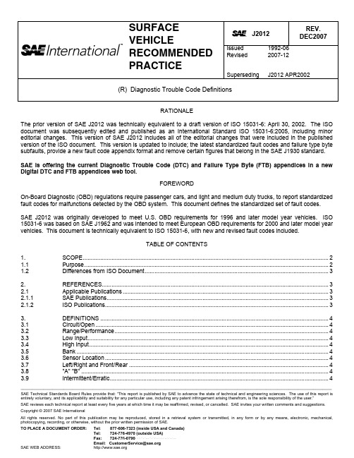
__________________________________________________________________________________________________________________________________________ SAE Technical Standards Board Rules provide that: “This report is published by SAE to advance the state of technical and engineering sciences. The use of this report is entirely voluntary, and its applicability and suitability for any particular use, including any patent infringement arising therefrom, is the sole responsibility of the user.” SAE reviews each technical report at least every five years at which time it may be reaffirmed, revised, or cancelled. SAE invites your written comments and suggestions. Copyright © 2007 SAE InternationalAll rights reserved. No part of this publication may be reproduced, stored in a retrieval system or transmitted, in any form or by any means, electronic, mechanical, photocopying, recording, or otherwise, without the prior written permission of SAE. TO PLACE A DOCUMENT ORDER: Tel: 877-606-7323 (inside USA and Canada) Tel: 724-776-4970 (outside USA)Fax: 724-776-0790Email: CustomerService@ SAE WEB ADDRESS:h ttp://J2012Issued Revised 2007-12 (R) Diagnostic Trouble Code DefinitionsRATIONALEThe prior version of SAE J2012 was technically equivalent to a draft version of ISO 15031-6: April 30, 2002. The ISO document was subsequently edited and published as an International Standard ISO 15031-6:2005, including minor editorial changes. This version of SAE J2012 includes all of the editorial changes that were included in the published version of the ISO document. This version is updated to include; the latest standardized fault codes and failure type byte subfaults, provide a new fault code appendix format and remove certain figures that belong in the SAE J1930 standard. SAE is offering the current Diagnostic Trouble Code (DTC) and Failure Type Byte (FTB) appendices in a new Digital DTC and FTB appendices web tool.FOREWORDOn-Board Diagnostic (OBD) regulations require passenger cars, and light and medium duty trucks, to report standardized fault codes for malfunctions detected by the OBD system. This document defines the standardized set of fault codes. SAE J2012 was originally developed to meet U.S. OBD requirements for 1996 and later model year vehicles. ISO 15031-6 was based on SAE J1962 and was intended to meet European OBD requirements for 2000 and later model year vehicles. This document is technically equivalent to ISO 15031-6, with new and revised fault codes included.TABLE OF CONTENTS1. SCOPE..........................................................................................................................................................2 1.1 Purpose.........................................................................................................................................................2 1.2 Differences from ISO Document...................................................................................................................32. REFERENCES..............................................................................................................................................3 2.1 Applicable Publications.................................................................................................................................3 2.1.1 SAE Publications...........................................................................................................................................3 2.1.2 ISO Publications............................................................................................................................................33. DEFINITIONS ...............................................................................................................................................4 3.1 Circuit/Open..................................................................................................................................................4 3.2 Range/Performance......................................................................................................................................4 3.3 Low Input.......................................................................................................................................................4 3.4 High Input......................................................................................................................................................4 3.5 Bank..............................................................................................................................................................4 3.6 Sensor Location............................................................................................................................................4 3.7 Left/Right and Front/Rear .............................................................................................................................4 3.8 "A" "B"...........................................................................................................................................................4 3.9Intermittent/Erratic (4)--``,,`,``,,`,`,``,``,,,``,``,`,-`-`,,`,,`,`,,`---4.GENERAL SPECIFICATIONS (5)5.FORMAT STRUCTURE (5)5.1Description (5)5.2ISO/SAE Controlled Codes (Core DTCs) (7)5.3Manufacturer Controlled Codes (Non-Uniform DTCs) (7)5.4Body System Groupings (7)5.4.1B0XXX ISO/SAE Controlled (7)5.4.2B1XXX Manufacturer Controlled (7)5.4.3B2XXX Manufacturer Controlled (7)5.4.4B3XXX Reserved by Document (7)5.5Chassis System Groupings (7)5.5.1C0XXX ISO/SAE Controlled (7)5.5.2C1XXX Manufacturer Controlled (7)5.5.3C2XXX Manufacturer Controlled (7)5.5.4C3XXX Reserved by Document (7)5.6Powertrain System Groupings (8)5.6.1P0XXX ISO/SAE Controlled (8)5.6.2P1XXX Manufacturer Control (8)5.6.3P2XXX ISO/SAE Controlled (8)5.6.4P3XXX Manufacturer Controlled and ISO/SAE Reserved (8)5.7Network Groupings (8)5.7.1U0XXX ISO/SAE Controlled (8)5.7.2U1XXX Manufacturer Controlled (8)5.7.3U2XXX Manufacturer Controlled (8)5.7.4U3XXX Manufacturer Controlled and ISO/SAE Reserved (8)6.DIAGNOSTIC TROUBLE CODE DESCRIPTIONS (8)6.1Diagnostic Trouble Code Application (8)6.2Powertrain Systems (8)6.3Body Systems (9)6.4Chassis Systems (9)6.5Network and Vehicle Integration Systems (9)7.CHANGE REQUESTS (9)8.NOTES (11)8.1Marginal Indicia (11)APPENDIX A0 - (NORMATIVE) DIAGNOSTIC TROUBLE CODE NAMING GUIDELINES (12)APPENDIX B0 - BODY SYSTEMS (15)APPENDIX C0 - CHASSIS SYSTEMS (20)APPENDIX D0 - POWERTRAIN SYSTEMS (24)APPENDIX E0 - NETWORK SYSTEMS (110)APPENDIX F0 - FAILURE TYPE BYTE (128)1. SCOPE1.1 PurposeThis document supersedes SAE J2012 APR2002, and is technically equivalent to ISO 15031-6:2005 with the exceptions described in Section 1.2.This document is intended to define the standardized Diagnostic Trouble Codes (DTC) that On-Board Diagnostic (OBD) systems in vehicles are required to report when malfunctions are detected.--``,,`,``,,`,`,``,``,,,``,``,`,-`-`,,`,,`,`,,`---This document includes:a. Diagnostic Trouble Code format.b. A standardized set of Diagnostic Trouble Codes and descriptionsc. A standardized set of Diagnostic Trouble Codes subtypes known as Failure Types1.2 Differences from ISO DocumentThe differences to the ISO document 15031-6:2005 are the removal of figures in Section 3. The figures have been moved to SAE J1930. The DTC and FTB appendixes have been updated to reflect the latest industry standardized DTC and FTB definitions.2. REFERENCES2.1 Applicable PublicationsThe following publications form a part of this specification to the extent specified herein. Unless otherwise specified, the latest issue of SAE publications shall apply.2.1.1 SAEPublicationsAvailable from SAE International, 400 Commonwealth Drive, Warrendale, PA 15096-0001, Tel: 877-606-7323 (inside USA and Canada) or 724-776-4970 (outside USA), .SAE J1930 Electrical/Electronic Systems Diagnostic Terms, Definitions, Abbreviations, and AcronymsSAE J1978 OBD II Scan ToolSAE J1979 E/E Diagnostic Test Modes--``,,`,``,,`,`,``,``,,,``,``,`,-`-`,,`,,`,`,,`---2.1.2 ISOPublicationsAvailable from ANSI, 25 West 43rd Street, New York, NY 10036-8002, Tel: 212-642-4900, .ISO/TR 15031-2:2004 Road vehicles—Communication between vehicle and external equipment for emissions-related diagnostics—Part 2: Terms, definitions, abbreviations and acronymsISO 15031-4:2005 Road vehicles—Communication between vehicle and external test equipment for emissions-related diagnostics—Part 4: External test equipmentISO 15031-5:2006 Road vehicles—Communication between vehicle and external test equipment for emissions-related diagnostics—Part 5: Emissions related diagnostic servicesISO 15031-6:2005 Road vehicles—Communication between vehicle and external test equipment for emissions-related diagnostics—Part 6: Diagnostic trouble code definitionsISO 14229-1 Road vehicles—Unified diagnostics services (UDS)—Part 1: Specification and requirements3. DEFINITIONSThis document is not intended to be used for terms and definitions of vehicle component terminology. Many related vehicle technologies are defined in SAE J1930. 3.1 Circuit/OpenFixed value or no response from the system where specific high or low detection is not feasible or can be used in conjunction with circuit low and high codes where all three circuit conditions can be detected. 3.2 Range/PerformanceCircuit is in the normal operating range, but not correct for current operating conditions, it may be used to indicate stuck or skewed values indicating poor performance of a circuit, component, or system. 3.3 Low InputCircuit voltage, frequency, or other characteristic measured at the control module input terminal or pin that is below the normal operating range. 3.4 High InputCircuit voltage, frequency, or other characteristic measured at the control module input terminal or pin that is above the normal operating range. 3.5 BankSpecific group of cylinders sharing a common control sensor, bank 1 always contains cylinder number 1, bank 2 is the opposite bank.NOTE: If there is only one bank, use bank #1 DTCs and the word bank may be omitted. With a single "bank" systemusing multiple sensors, use bank #1. 3.6 Sensor LocationLocation of a sensor in relation to the engine air flow, starting from the fresh air intake through to the vehicle tailpipe or fuel flow from the fuel tank to the engine in order numbering 1,2,3 and so on. 3.7Left/Right and Front/RearComponent identified by its position as if it can be viewed from the drivers seating position. 3.8 "A" "B"Where components are indicated by a letter (e.g., A, B, C, etc.) this would be manufacturer defined. 3.9 Intermittent/ErraticThe signal is temporarily discontinuous, the duration of the fault is not sufficient to be considered an open or short, or the rate of change is excessive.--``,,`,``,,`,`,``,``,,,``,``,`,-`-`,,`,,`,`,,`---4. GENERAL SPECIFICATIONSThe following table specifies systems, code categories, hexadecimal values and particular sections of electrical/electronic systems diagnostic.TABLE 1 - GENERAL CODE SPECIFICATIONSSystem Code Categories Hex Value AppendixBody B0xxx - B3xxx8xxx - B xxx B0Chassis C0xxx - C3xxx4xxx - 7xxx C0Powertrain P0xxx - P3xxx0xxx - 3xxx P0Network U0xxx - U3xxx C xxx - F xxx U0The recommended DTCs consist of a three digit hexadecimal code preceded by an alphanumeric designator. The alphanumeric designators are "B0", "B1", B2", "B3", "C0", "C1", C2", "C3", "P0", "P1", P2", "P3", "U0", "U1", U2", "U3", corresponding to four sets of body, four sets of chassis, four sets of powertrain and four sets of network trouble codes. The code structure itself is partially open-ended. A portion of the available numeric sequences (portions of "B0", "C0", "P0", “P2”, “P3”, "U0", and “U3”) is reserved for uniform codes assigned by this or future updates. Detailed specifications of the DTC format structure are specified in Section 5.Most circuit, component, or system diagnostic trouble codes that do not support a subfault strategy are specified by four basic categories:— General Circuit /Open— Range/Performance— Circuit Low— Circuit HighCircuit Low is measured with the external circuit, component, or system connected. The signal type (voltage, frequency, etc.) shall be included in the message after Circuit Low.Circuit High is measured with the external circuit, component, or system connected. The signal type (voltage, frequency, etc.) may be included in the message after Circuit High.5. FORMAT STRUCTURE--``,,`,``,,`,`,``,``,,,``,``,`,-`-`,,`,,`,`,,`---5.1 DescriptionThe diagnostic trouble code consists of an alphanumeric designator, B0 -- B3 for body, C0 -- C3 for chassis, P0 -- P3 for powertrain, and U0 -- U3 for network communication, followed by a hexadecimal number. The assignment of the proper alpha designator should be determined by the area most appropriate for that function. In most cases, the alpha designator will be implied since diagnostic information will be requested from a particular controller. However, this does not imply that all codes supported by a particular controller shall have the same alphanumeric designator. The codes are structured as in Figure 1.FIGURE 1 - STRUCTURE OF DIAGNOSTIC TROUBLE CODESEXAMPLE: The 2-byte DTC as a data bus value $9234 would be displayed to technicians as the manufacturer controlled body code B1234, see Figure 2.DTC HIGH BYTE DTC LOW BYTE$9 $2$3 $41 0 0 1 0 0 1 0 0 0 1 1 0 1 0 0B 1 2 3 4FIGURE 2 - EXAMPLE OF 2-BYTE DIAGNOSTIC TROUBLE CODE STRUCTUREEXAMPLE: The 3-byte DTC as a data bus value $923400 would be displayed to technicians as the manufacturer controlled body code B1234-00, see Figure 3. See appendix FTB for DTC Low Byte (Failure Type Byte)definitions. The low byte shall be displayed in hexadecimal format, e.g. $1A shall be displayed as 1A.DTC HIGH BYTE DTC MIDDLE BYTE DTC LOW BYTE$3 $4 $0 $0 $9 $21 0 0 1 0 0 1 0 0 0 1 1 0 1 0 0 0 0 0 0 0 0 0 0B 1 2 3 4 0 0FIGURE 3 - EXAMPLE OF 3-BYTE DIAGNOSTIC TROUBLE CODE STRUCTURE--``,,`,``,,`,`,``,``,,,``,``,`,-`-`,,`,,`,`,,`---Codes have been specified to indicate a suspected trouble or problem area and are intended to be used as a directive to the proper service procedure. To minimize service confusion, fault codes should not be used to indicate the absence of problems or the status of parts of the system, (e.g. powertrain system O.K., or MIL activated), but should be confined to indicate areas in need of service attention.Ranges have been expanded from 100 numbers to 256 by using the hexadecimal base 16 number system.5.2 ISO/SAE Controlled Codes (Core DTCs)ISO/SAE controlled diagnostic trouble codes are those codes where industry uniformity has been achieved. These codes are common enough across most manufacturers' applications that a common number and fault message could be assigned. All unspecified numbers in each grouping are ISO/SAE reserved for future growth. Although service procedures may differ widely amongst manufacturers, the fault being indicated is common enough to be assigned a particular fault code. Codes in this area are not to be used by manufacturers until they have been approved by ISO/SAE.5.3 Manufacturer Controlled Codes (Non-Uniform DTCs)Areas within each alpha designator have been made available for manufacturer-controlled DTCs. These are fault codes that will not generally be used by a majority of the manufacturers due to basic system differences, implementation differences, or diagnostic strategy differences. Each vehicle manufacturer or supplier who designs and specifies diagnostic algorithms, software, and diagnostic trouble codes are strongly encouraged to remain consistent across their product line when assigning codes in the manufacturer controlled area. For powertrain codes, where possible, the same groupings should be used as in the ISO/SAE controlled area, i.e. 100's and 200's for fuel and air metering, 300's for ignition system or misfire, etc.While each manufacturer has the ability to define the controlled DTCs to meet their specific controller algorithms, all DTC descriptions shall meet SAE J1930 or ISO 15031-2.5.4 Body System GroupingsDTC numbers and descriptions are given in appendix B0.5.4.1 B0XXX ISO/SAE Controlled5.4.2 B1XXX Manufacturer Controlled5.4.3 B2XXX Manufacturer Controlled5.4.4 B3XXX Reserved by Document5.5 Chassis System GroupingsDTC numbers and descriptions are given in appendix C0.5.5.1 C0XXX ISO/SAE Controlled5.5.2 C1XXX Manufacturer Controlled5.5.3 C2XXX Manufacturer Controlled5.5.4 C3XXX Reserved by Document--``,,`,``,,`,`,``,``,,,``,``,`,-`-`,,`,,`,`,,`---5.6 Powertrain System GroupingsDTC numbers and descriptions are given in appendix P0.5.6.1 P0XXX ISO/SAE Controlled5.6.2 P1XXX Manufacturer Control5.6.3 P2XXX ISO/SAE Controlled5.6.4 P3XXX Manufacturer Controlled and ISO/SAE Reserved5.7 Network GroupingsDTC numbers and descriptions are given in appendix U0.--``,,`,``,,`,`,``,``,,,``,``,`,-`-`,,`,,`,`,,`---5.7.1 U0XXX ISO/SAE Controlled5.7.2 U1XXX Manufacturer Controlled5.7.3 U2XXX Manufacturer Controlled5.7.4 U3XXX Manufacturer Controlled and ISO/SAE Reserved6. DIAGNOSTIC TROUBLE CODE DESCRIPTIONS6.1 Diagnostic Trouble Code ApplicationRecent developments have expanded the scope of this documentation to include additional DTCs and descriptions for network systems, body systems, and chassis systems. Two different DTC application methods are required depending on the system. Powertrain DTCs require the assignment of a unique DTC number and description for each failure mode (e.g.: circuit low, circuit high, rationality, etc). Body and chassis systems descriptions are more general and require the assignment of a single DTC number and description for each component, not failure mode. Unique body and chassis failure mode identification is still possible, but is dependent upon using diagnostic protocols that support a subfault failure strategy. One example is ISO 14229-1, which uses a “Failure Type Byte” associated with each DTC to describe the failure mode (e.g.: circuit low, circuit high, rationality, etc). However any protocol supporting a subfault strategy will work with these DTCs. Manufacturers must select the appropriate failure mode to apply to the base DTC description.6.2 Powertrain SystemsThe powertrain systems category covers functions that include engine, transmission and associated drivetrain accessories. For powertrain systems, each specified fault code has been assigned a description to indicate the circuit, component or system area that was determined to be at fault. The descriptions are organized such that different descriptions related to a particular sensor or system are grouped together. In cases where there are various fault descriptions for different types of faults, the group also has a "generic" description as the first code/message of the group.A manufacturer has a choice when implementing diagnostics, based on the specific strategy and complexity of the diagnostic.Where more specific fault descriptions for a circuit, component, or system exist, the manufacturer should choose the code most applicable to their diagnosable fault. The descriptions are intended to be somewhat general to allow manufacturers to use them as often as possible yet still not conflict with their specific repair procedures. The terms "low" and "high" when used in a description, especially those related to input signals, refer to the voltage, frequency, etc. at the pin of the controller. The specific level of "low" and "high" shall be specified by each manufacturer to best meet their needs.For example, in diagnosing a 5 V reference Throttle Position Sensor (TP Sensor), if the input signal at the Powertrain Control Module (PCM) is stuck at near 0 V, a manufacturer has the flexibility to select from either of two codes - P0120 (Throttle/Pedal Position Sensor/Switch A Circuit) or P0122 (Throttle/Pedal Position Sensor/Switch A Circuit Low), depending on the manufacturer's diagnostic procedures. If the input signal at the PCM is stuck at near 5 V, a manufacturer has the flexibility to select from either of two codes - P0120 (Throttle/Pedal Position Sensor/Switch A Circuit) or P0123 (Throttle/Pedal Position Sensor/Switch A Circuit High), depending on the manufacturer's diagnostic procedures. If the input signal at the PCM is stuck at 1.5 V at idle instead of the expected 1.0 V, the manufacturer has the flexibility to select from either of two codes - P0120 (Throttle/Pedal Position Sensor/Switch A Circuit) or P0121 (Throttle/Pedal Position Sensor/Switch A Circuit Range/Performance), depending on the manufacturer's diagnostic procedures. The root cause of the higher than expected TP Sensor voltage may be either a faulty TP Sensor, corrosion in the TP Sensor connections or an improperly adjusted throttle plate. Identification of the root cause is done using the diagnostic procedures and is not implied by the DTC message, thus allowing the manufacturer the flexibility in assigning DTCs.6.3 Body SystemsThe body systems category covers functions that are, generally, inside of the passenger compartment. These functions provide the vehicle occupants with assistance, comfort, convenience, and safety. Each specified trouble code has been assigned a description to indicate the component or system area that was determined to be at fault. Unlike powertrain systems, the body system trouble code descriptions are intended to be general. Powertrain DTCs typically include separate DTCs for each failure mode (e.g.: circuit low, circuit high, rationality, etc) within each DTC description. Body system DTCs are designed to only support the base component in the description, which makes these DTCs dependent upon diagnostic protocols that support a subfault failure strategy. Manufacturers must select the appropriate failure mode (e.g.: circuit short to ground, circuit short to battery, signal plausibility failure, etc) to apply to the general DTC description. The supported body subsection included in this group is currently Restraints. 6.4 Chassis SystemsThe chassis systems category covers functions that are, generally, outside of the passenger compartment. These functions typically include mechanical systems such as brakes, steering and suspension. Each specified trouble code has been assigned a description to indicate the component or system area that was determined to be at fault. Unlike powertrain systems, the chassis system trouble code descriptions are intended to be general. Powertrain DTCs typically include separate DTCs for each failure mode (e.g.: circuit low, circuit high, rationality, etc) within each DTC description. Chassis system DTCs are designed to only support the base component in the description, which makes these DTCs dependent upon diagnostic protocols that support a subfault failure strategy. Manufacturers must select the appropriate failure mode (e.g.: circuit short to ground, circuit short to battery, signal plausibility failure, etc) to apply to the general DTC description. The supported chassis subsections included in this group are currently Brakes and Traction Control. 6.5Network and Vehicle Integration SystemsThe network communication and vehicle integration systems category covers functions that are shared among computers and/or systems on the vehicle. Each specified trouble code has been assigned a description to indicate the component or system area that was determined to be at fault. The descriptions of data links are intended to be general in order to allow manufacturers to use them for different communication protocols. The descriptions of control modules are intended to be general in order to allow manufacturers to reuse the DTC for new control modules as technologies evolve. Also, the descriptions may be supplemented with additional subfault information such as the “Failure Type Byte” data defined in appendix FTB. The subsections included in this group are Network Electrical, Network Communication, Network Software, Network Data, and Control Module/Power Distribution. 7. CHANGE REQUESTSUse this form to request new industry standard DTCs.--``,,`,``,,`,`,``,``,,,``,``,`,-`-`,,`,,`,`,,`---Request Form for New ISO 15031-6/SAE J2012 Controlled DTC What is the purpose of the component, circuit, or system?Example: Exhaust Gas Recirculation.What is the purpose of the diagnostic?Example: detect low EGR flowRequested Group Number_________________________________________________ Requested DTC Number__________________________________________________ Requested DTC Nomenclature_____________________________________________ Example: EGR Low Flow DetectedRequested by:__________________________________________________________ Phone/Fax_________________________________________Email______________________________________________Address____________________________________________Date:Please send completed form(s) either to:FAKRA Normenausschuß Kraftfahrzeuge Postfach 17 05 63D-60079 Frankfurt/MainGermanyATTN: ISO/TC22/SC3/WG1SAE Headquarters755 West Big Beaver RoadSuite 1600Troy, MI 48084USAATTN: J2012 Committee Chairman--``,,`,``,,`,`,``,``,,,``,``,`,-`-`,,`,,`,`,,`---8. NOTES8.1 Marginal IndiciaThe change bar (l) located in the left margin is for the convenience of the user in locating areas where technical revisions have been made to the previous issue of the report. An (R) symbol to the left of the document title indicates a complete revision of the report.PREPARED BY THE SAE VEHICLE ELECTRICAL AND ELECTRONICSDIAGNOSTIC SYSTEMS STANDARDS COMMITTEE--``,,`,``,,`,`,``,``,,,``,``,`,-`-`,,`,,`,`,,`---APPENDIX A0 - (NORMATIVE)DIAGNOSTIC TROUBLE CODE NAMING GUIDELINESA.1 DISCUSSIONTables A01, A02, A03, A04 provide guidelines to help in determining DTC descriptions.Appendix B0 shows applications for recommended industry common trouble codes for the body systems, Appendix C0 shows applications for chassis systems, Appendix P0 shows applications for powertrain systems and Appendix U0 shows applications for network control systems. The DTCs in appendix P0 include systems that might be integrated into an electronic control module that would be used for controlling engine functions, such as fuel, spark, idle speed, and vehicle speed (cruise control), as well as those for transmission control. The fact that a code is recommended as a common industry code does not imply that it is a required code (legislated), an emission related code, nor that it indicates a fault that will cause the malfunction indicator to be illuminated.TABLE A01 - DTC NAMING GUIDELINES FOR SIGNALS FROM COMPONENTSComponent/System ISO 15031-2/SAE J1930(1)AcronymISO 15031-2/SAEJ1930(1)Modifier(if used)(1) Noun Name(1)Circuit(1)Intermittent(if used)(1)State(if used)(1)Parameter(if used)(1)Location(if used)(1)ThrottlePosition TP Sensor Circuit Low Voltage Throttle Position TP Sensor Circuit PerformanceManifold Absolute Pressure MAPSensor Circuit High VoltageEngine CoolantTemperatureECT Sensor Circuit Low Voltage Intake Air Temperature IAT Sensor Circuit High VoltageVehicle Speed Sensor VSS included inacronymCircuit High VoltageVehicle Speed Sensor VSS included inacronymCircuit IntermittentHeated Oxygen Sensor HO2S included inacronymCircuitHeated Oxygen Sensor HO2S included inacronym Circuit Low Voltage Bank (B1)Sensor 1 (S1)Idle Air Control IAC Valve Circuit Low VoltageMass Air Flow MAF Sensor Circuit High FrequencyMass Air Flow MAF Sensor Circuit PerformanceKnock Sensor KS included inacronymCircuit Bank 1Knock Sensor KS included inacronymCircuit PerformanceCrankshaft Position CKP Sensor CircuitEvaporative Emissions EVAP CanisterPurgeValve CircuitEngine Speed RPM InputCircuitAir Conditioning A/C Clutch N/A Circuit LowVoltage --``,,`,``,,`,`,``,``,,,``,``,`,-`-`,,`,,`,`,,`---。
- 1、下载文档前请自行甄别文档内容的完整性,平台不提供额外的编辑、内容补充、找答案等附加服务。
- 2、"仅部分预览"的文档,不可在线预览部分如存在完整性等问题,可反馈申请退款(可完整预览的文档不适用该条件!)。
- 3、如文档侵犯您的权益,请联系客服反馈,我们会尽快为您处理(人工客服工作时间:9:00-18:30)。
塞普拉斯40亿美元合并飞索汽车芯片新巨头
来源:互联网
[导读]全球知名电子芯片制造商塞普拉斯半导体(Cypress)1日宣布,计划与全球最大的闪存研发生产商飞索半导体(Spansion)合并,该交易涉及股票金额达40亿美元。
关键词:塞普拉斯飞索
为提高效率、抢占市场,近期多家芯片公司联手扩大规模。
全球知名电子芯片制造商塞普拉斯半导体(Cypress)1日宣布,计划与全球最大的闪存研发生产商飞索半导体(Spansion)合并,该交易涉及股票金额达40亿美元。
受合并消息提振,1日飞索股价盘后大涨。
今年以来,飞索股价已累计攀升64.5%。
新公司年收入将超20亿美元
塞普拉斯与飞索表示,合并交易完成后,将诞生一家年收入超过20亿美元的嵌入式芯片供应商,合并后的新公司有望将成为全球第四或第五大汽车芯片供应商。
新公司一半的收入将来自NOR闪存和SRAM内存业务,其他收入将来自微控制器和模拟器件。
NOR闪存是目前市场上两种主要的非易失闪存技术之一。
NOR的特点是芯片内执行,应用程序可以直接在闪存内运行,不必再把代码读到系统中,从而提高了传输效率。
SRAM 是英文Static RAM的缩写,即静态随机存储器。
它是一种具有静止存取功能的内存,无需刷新电路即能保存内部存储的数据。
赛普拉斯总裁兼首席执行官(CEO)罗杰斯将继续担任合并后的新公司CEO,公司仍将被命名为赛普拉斯。
飞索CEO约翰·凯斯波特将成为新公司董事,新董事会8名董事将分别来自两家公司的高管。
尽管在这两家公司中,赛普拉斯的规模稍小,但其持续盈利。
飞索因NOR闪存业务下降,长期在困局中挣扎,一度濒临破产边缘。
根据合并协议,飞索股东可凭其股份每股换取2.457股赛普拉斯股票。
两公司的现有股东将持有合并后新公司约50%的股份。
IHS科技部门车载嵌入式处理器首席分析汤姆·汉肯伯格称,2013年,赛普拉斯的单片微型计算机(MCU)销售额全球排名第12,飞索排名第10。
汉肯伯格预计:“两家公司合并后,以今年前三季度的单片机销售额来推算,新公司全年销售额能达到10亿美元,排名将超越目前排名第九的三星电子,但会以2亿美元的差距落后于爱特梅尔公司(Atmel)。
”
芯片业现并购热潮
此前,安华高科与LSI合并成立了规模达50亿美元的新公司;中国台湾联发科技股份有限公司也和MStar合并;美国美光(Micron)也通过收购尔必达(Elpida)创立了新的内存巨头。
赛普拉斯首席技术官(CTO)奥利维拉称:“在此背景下,赛普拉斯与飞索的合并故事很简单。
两家公司都在花时间在并购市场积极寻找对象。
我们收购全球领先的非易失性铁电半导体供应商Ramtron后,这几年一直在寻找更大的收购目标,直到得知飞索也在做同样的计划。
最新合并交易反映了两家公司对于此轮芯片产业整合的共识。
”
尽管如此,赛普拉斯和飞索有着不同的内存业务,产品重合性较小。
赛普拉斯的主要业务和产品针对SRAM内存;而飞索在收购了SK海力士半导体公司后,致力于大力扩展NOR 闪存业务。
飞索执行副总裁哈桑·艾尔-寇里称:“在汽车电子单片机市场上,赛普拉斯主要服务于后端市场,飞索的产品则主要在人机界面领域,如前显示屏控制。
在白色家电市场,赛普拉斯的产品也集中于主板控制,我们则在面板控制中。
两家公司的技术和应用都是互补的。
”
赛普拉斯半导体公司1982年成立,总部设在美国加利福尼亚州。
该公司主要生产高性能芯片产品,用于数据传输、远程通讯、PC和军用系统,可为消费、移动电话、计算、数据通信、汽车、工业和军事等多种行业和市场提供服务。
飞索半导体于2003年由AMD和富士通的微控制器和模拟事业部整合各自的闪存业务合并而成,后者是当时日本第二大车用单片机供应商。
飞索目前的产品主要应用于通讯、汽车、网络和消费电子等领域。
由于iPhone市场份额高达约33%,HomeKit在美国将有一个良好的开端。
如果Apple Watch明年大获成功,它可能说服更多公司推出与HomeKit兼容的设备。
谷歌Nest
谷歌拥有世界上最大的互联网搜索引擎和移动操作系统Android,并通过Google Now 语音助理把这两者紧密地联系在一起。
这是谷歌把Google Now整合在Nest中的原因,使用户可以通过语音命令控制他们的智能设备。
谷歌6月份宣布,电子产品、汽车和通用遥控器,都将支持Nest Learning Thermostat。
Jawbone、Whirlpool、LIFX和奔驰等公司都参与谷歌的Works With Nest项目,开发与Nest 兼容的产品。
谷歌的智能家居战略与其移动战略相似:开发智能家居操作系统,然后吸引尽可能多的硬件合作伙伴。
谷歌还在收购竞争对手。
继收购Nest后,谷歌又收购了两家智能家居创业公司——WiFi摄像头厂商Dropcam和智能家居平台开发商 Revolv,进一步扩大了在智能家居市场上的存在。
谷歌缘何会陷入困境?
在智能家居大战中,谷歌与苹果相比略有优势,但隐私担忧可能使得Nest无法得到主流消费者青睐。
谷歌系智能设备可能非常方便,但作为依靠精准广告创收的公司,谷歌的WiFi摄像头和云设备会面临严重质疑。
在Black Hat大会上,安全研究人员仅用“10-15秒”就攻破了Nest,引发了对智能家居设备安全的担忧。
过去,谷歌曾多次率先推出不够成熟的服务,然后被苹果后来居上。
例如,由于Softcard 合作伙伴的阻击,谷歌钱包从未真正在消费者中流行。
但Softcard却对苹果Apple Pay大开绿灯。
谷歌还计划利用Google Health,把所有电子病历同步到一个单一平台,但该平台因隐私担忧和医疗机构缺乏兴趣而于2011年遭到抛弃。
今年早些时候,苹果的HealthKit则大获成功,迅速获得美国各大电子病历公司和保险公司的支持。
谷歌在智能家居领域可能重蹈在其他领域的覆辙。
对谷歌真正意图的担忧使得许多人不敢在家中安装Nest温控器。
由于苹果几乎没有广告业务,目的也只是把智能家居设备与其移动设备相连,极有可能赢得智能家居大战。
因此,业内人士认为苹果将在即将展开的智能家居大战中占得上风。