Compact microstrip LPF微带低通滤波器
微带滤波器书目
Microstrip Filter ReferencesUpdated 27 February 20031.Chandler, S.R., I.C. Hunter, and J.G. Gardiner, "Active Tunable Bandpass Filter," IEEEMicrowave and Guided Wave Letters, V ol. 3, No. 3, Mar 1993, pp. 70-71.2.Cohn, S.B., "Parallel-Coupled Transmission-Line-Resonator Filters," IRE Transactions onMicrowave Theory and Techniques, Apr 1958, pp. 223-231.3.Cristal, E.G., "New Design Equations for a Class of Microwave Filters," IEEETransactions on Microwave Theory and Techniques, May 1971, pp. 486-490.4.Dalby, A.B., "Interdigital Microstrip Circuit Parameters Using Empirical Formulas andSimplified Model," GMTT-78, pp. 223-226.5.Dell-Imagine, R.A., "A Parallel Coupled Microstrip Filter Design Procedure," IEEEG-MTT 1970 Digest, pp. 29-32.6.D'Inzeo, G., F. Giannini, and R. Sorrentino, "Novel Microwave Integrated LowpassFilters," Electronics Letters, V ol. 15, No. 9, 26 Apr 1979, pp. 258-260.7.Denig, C., "Using Microstrip CAD Programs to Analyze Microstrip Interdigital Filters,"Microwave Journal, Mar 1989, pp. 147-152.8.Fithian, M., "Absorptive Directional Filters," RF Design, pp. 41-46.9.Gupta, C., "Design of Parallel Coupled Line Filter with Discontinuity Compensation inMicrostrip," Microwave Journal, Dec 1979, pp. 39-43, 57.10.Huruya, J. and R. Sato, "Transmission Characteristics and a Design Method ofTransmission-Line Low-Pass Filters with Multiple Pairs of Coincident Zeros and Multiple Pairs of Coincident Poles," IEEE Transactions on Microwave Theory and Techniques, V ol. MTT-28, No. 8, Aug 1980.11.Jokela, K.T., "Narrow-Band Stripline or Microstrip Filters with Transmission Zeros atReal and Imaginary Frequencies," IEEE Transactions on Microwave Theory and Techniques, V ol. MTT-28, No. 6, Jun 1980, pp. 542-547.12.Katehi, P.B. and L.P. Dunleavy, "Microstrip Filter Design Including Dispersion Effectsand Radiation Losses," 1986 IEE MTT-S Digest, pp. 687-690.13.Kunieda, H., "General Design Method for Distributed Coupled-Line Bandpass Filter,"Proceedings of the 1979 ISCAS, pp. 703-706.14.Maekawa, E. and N. Nagai, "New Second-Order All-Pass Microwave Network,"Proceedings of the 1979 ISCAS, pp. 699-702.15.Makimoto, M. and M. Sagawa, "Varactor Tuned Bandpass Filters Using Microstrip-LineRing Resonators," 1986 IEEE MTT-S Digest, pp. 411-414.16.Mehdizadeh, M. and B. Smilowitz, "High Speed Varactor Tuned Notch Filter," 1985IEEE MTT-S Digest, pp. 531-534.17.Mehran, R., "Computer-Aided Design of Microstrip Filters Considering Dispersion, Loss,and Discontinuity Effects," IEEE Transactions on Microwave Theory and Techniques, V ol.MTT-27, No. 3, Mar 1979, pp. 239-245.18.Minnis, B.J., "Printed Circuit Coupled-Line Filters for Bandwidths Up to and GreaterThan an Octave," IEEE Transactions on Microwave Theory and Techniques, Vol. MTT-29, No. 3, Mar 1981, pp. 215-222.19.Onoda, M. and H. Kunieda, "Lumped-Element Equivalent Representations ofTransmission-Line Networks by Half-Angle Richards' Variable," Proceedings of the 1978 ISCAS, pp. 946-950.20.Patterson, H., T. Kajita, and C.Y. Ho, "Design of a Wideband Miniature MicrowaveConverter with Wide Dynamic Range," Microwave Journal, Sep 1990, pp. 115-130.21.Perez, R., "Avoiding Doubts in Low-Pass Filters," Microwave System News, Jun 1979,pp. 58-65.22.Presser, A., "High-Speed, Varactor-Tunable Microwave Filter Element," 1979 IEEEMTT-S Digest, pp. 416-418.23.Rhodes, J.D. and J.E. Dean, "MIC Broadband Filters and Contiguous Multiplexers,"Proceedings of the 9th European Microwave Conference, 1979, pp. 407-411.24.Saad, A.M.K. and K. Schunemann, "Design and Performance of Fin-Line BandpassFilters," Proceedings of the 9th European Microwave Conference, 1979, pp. 397-401.25.Saulich, G., "A Stripline Filter Derived From Directional Couplers," Proceedings of the9th European Microwave Conference, 1979, pp. 381-385.26.Sierra, M., "Miniature Microstrip Bandpass Filter with Large Stopbands," ElectronicsLetters, Vol. 15, No. 9, 24 Apr 1980, pp. 340-342.27.Toyoda, S., "Microstrip Variable Band-Pass Filters Using V aractor-Diodes," 1980 IEEEMTT-S Digest, pp. 153-155.28.Vincze, A.D., "Practical Design Approach to Microstrip Combline-Type FIlters," IEEETransactions on Microwave Theory and Techniques, Vol. MTT- 22, No. 12, Dec 1974, pp.1171-1181.29.Wensel, R.J. and W.G. Erlinger, "Problems in Microstrip Filter Design," 1981 IEEEMTT-S Digest, pp. 203-205.30.Wong, J.S., "Microstrip Tapped-Line Filter Design," IEEE Transactions on MicrowaveTheory and Techniques, V ol. MTT-27, No. 1, Jan 1979, pp. 44-50.If you have any additional references on thissubject, please Email them to christrask@_==_ / and they will be added to this resource list.( ">(> )>^^Birdstein is a creation of Peter CassoMicrowave Filters, Impedance-Matching Networks, and Coupling Structures。
无源器件技术介绍-提高篇
图5带通滤波器基本构成 事实上,低通滤波器是整个滤波器设计的基础,包括带通滤波器、带阻滤波器和高通滤 波器均是低通滤波器变化而来。 比如低通滤波器到带通滤波器采用了如下的变换:
图 5 低通滤波器到带通滤波器元件转换示意图
Wuhan Hongxin Telecommunication Technologies Co., LTD
体积,以同轴腔为例,一个900MHz的8级滤波器,如果采用如下排列:
图 20 一个 8 级同轴腔示意图
Wuhan Hongxin Telecommunication Technologies Co., LTD 12
如果采用20mm×20mm的谐振腔,滤波器的总尺寸大约是50mm×200mm可能损耗是1.5dB, 而如果采用40mm×40mm的谐振腔,滤波器的总尺寸大约是100mm×380mm可能的损耗是 0.7dB。 Ø Ø 滤波器级数,滤波器级数越大,损耗越大。因此要获得一定的带外损耗,我们必须选择 合适的数学函数和尽可能少的级数。 当然还会有其它的一些因素,加工误差、电镀(镀银的质量)和表面光洁度等。
7
图11 WCDMA发射机和接收机采用双工器连接 l 信号的选择等, 中频滤波器带宽直接影响接收机的性能,实际上所有雷达通信 等接收机系统设计很大程度上就是滤波器指标的提出。
图12 接收机采用不同的中频滤波器的输出信号 (采用不同的带宽,信号的幅度并没有多少改变,而噪声能量却大大降低,滤波器带宽 越窄,噪声能量越低,这样信号越能够被检测而不被噪声干扰。) l 频率合成器中大量使用滤波器
无源器件技术介绍
提高篇
烽火科技集团 武汉虹信通信技术有限责任公司
目录
一、滤波器 ............................................................ 3 1.1 滤波器的理想特性 ................................................. 3 1.2 滤波器的电气符号 ................................................. 4 1.3 滤波器的的分类: ................................................. 4 1.4 滤波器的基本构成 ................................................. 5 1.5 滤波器的作用 ..................................................... 6 1.6 基本技术指标 ..................................................... 9 二、 功分器 .......................................................... 17 2.1 概述 ............................................................ 17 2.2 功分器的通用符号 ................................................ 18 2.3 功分器的技术指标 ................................................ 19 三、 耦合器与电桥 .................................................... 23 3.1 耦合器的符号 .................................................... 23 3.2 耦合器的技术指标 ................................................ 26 3.3 电桥 ............................................................ 30
基于HFSS的微带滤波器设计与应用

基于HFSS的微带滤波器设计与应用随着通信技术的不断发展,无线通信系统变得越来越普遍。
为了保证通信质量,必须对无线信号进行有效的过滤,因此滤波器成为了无线通信中最关键的组成部分之一。
基于微带技术的滤波器在无线通信中应用广泛,由于其体积小、重量轻、成本低、工艺简单的特点,在现代无线通信系统中依然扮演着不可替代的角色。
本文将基于HFSS软件,介绍微带滤波器的设计原理、设计流程、实现方法及其在无线通信中的应用。
一、微带滤波器的基本原理微带滤波器(Microstrip Filter)是一种基于微带线和附加衬底的元器件。
它通过在一条微带线(或几个相互交错的微带线)上挂载电容、电感和电阻等元件来实现滤波功能。
微带滤波器的基本结构如图1所示。
图1 微带滤波器基本结构图微带线的特性阻抗通常为50欧米,而微带滤波器需要特定的阻抗、通带和截止频带。
为了实现这些要求,滤波器需要在微带线模型上添加附加的元件来调整频率响应。
元件的安装可以使用多种方法,如串联、并联、交替安装等。
二、基于HFSS的微带滤波器设计流程首先需要明确滤波器的指标要求,包括通带和阻带的带宽、通带和阻带的中心频率、阻带衰减和通带波纹等参数。
这些指标根据具体应用需求而定,对于不同的应用场景可能存在较大差异。
2. 设计微带线结构在得到了所需的指标要求之后,需要根据这些要求设计微带线结构。
常用的方法是采用已有的文献或实验数据资料作为参考模板,进行修改和优化。
设计微带线时需要确定线宽、线距、衬底材料和厚度等参数,以实现所需的过渡阻抗和其他指标。
3. 添加补充元器件为了实现所需的频率响应,需要在微带线模型上添加各种补充元器件。
这些元器件包括电容、电感和电阻等,具体安装方式根据所需指标而定。
4. 模拟仿真使用HFSS软件进行微带滤波器的模拟仿真,得到滤波器的频率响应图和其他重要参数。
常规方法是在仿真软件中建立微带滤波器的三维模型,在模拟中通过修改材料参数、添加元器件、调整参数等方式进行仿真分析。
ADS低通滤波器设计PPT课件

滤波器原理图设计-----画微带线原理图
MLIN选项在左边Palette的TLines-Microstrip中
滤波器原理图设计-----电路参数设置
添加MSUB控件,双击添加参数 H:基板厚度(1.58mm) Er:基板相对介电常数(4.2) Mur:相对磁导率(1) Coud:金属电导率(5.88e7) Hu:封装高度(1.0e33mm) T:金属层厚度(0.035mm) TanD:损耗角正切(0.02) Rough:表面粗糙度(0mm)
滤波器原理图设计-----最终电路图
滤波器原理图设计-----优化仿真
点击优化图标 ,进行优化 稍待片刻即可查看效果
滤波器原理图设计-----优化仿真
然后点击update design 最终参数:
w0 = 2.77887 w1 = 12.6961 w2 = 424.403e-03 w3 = 10.1017 w4 = 475.833e-03 w5 = 10.12 w6 = 358.642e-03
点击 ,设置为
微带滤波器版图生成-----EM仿真
点击simulate,静待几分钟仿真出来的传输特性 出现这个是license的问题,去/thread-471722-1-1.html下载补丁
微带滤波器版图生成-----EM仿真
结论
观察得之滤波器在通带内(0~2.5GHz)插入损耗小于3.439dB,在4~5GHz之间大于28.096dB,满足设计要求
7
0.517
120
12.3
0.391252
2.45949
8
1
50
90
3.11445
16.7722
滤波器原理图设计-----添加变量
用LineCalc计算八段微带线的长和宽后我们要将各个数据添加到变量控件VAR中。 选择Insert->VAR在原理图中添加VAR然后双击,在“Name”文本框中输入变量的名称,“Variable Value”文本框中输入变量的初值,单机【ADD】添加变量 然后单击【Tune/Opt/Stat/Doe..】按钮打开参数优化对话框设置变量的取值范围,选择“Optimation”标签页。其中,“Enable/Disabled”表示该变量是否能被优化,“Minimum Value”表示可优化的最小值,“Maximum Value”表示可优化的最大值
ADS教程第6章
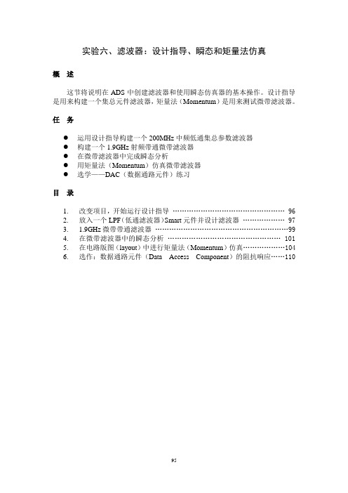
实验六、滤波器:设计指导、瞬态和矩量法仿真概述这节将说明在ADS中创建滤波器和使用瞬态仿真器的基本操作。
设计指导是用来构建一个集总元件滤波器,矩量法(Momentum)是用来测试微带滤波器。
任务●运用设计指导构建一个200MHz中频低通集总参数滤波器●构建一个1.9GHz射频带通微带滤波器●在微带滤波器中完成瞬态分析●用矩量法(Momentum)仿真微带滤波器●选学——DAC(数据通路元件)练习目录1.改变项目,开始运行设计指导 (96)2.放入一个LPF(低通滤波器)Smart元件并设计滤波器 (97)3. 1.9GHz微带带通滤波器 (99)4.在微带滤波器中的瞬态分析 (101)5.在电路版图(layout)中进行矩量法(Momentum)仿真 (104)6.选作:数据通路元件(Data Access Component)的阻抗响应 (110)步骤1.改变项目开始运行设计指导。
以下步骤将说明一个设计指导怎样既快速又准确地生产一个滤波器。
其方法与E-syn类似,但对期望的响应和拓扑结构有更多的选择和更强的控制。
a.进入ADS主窗口,然后点击File>open Project。
b.如果你被提示保存所有你当前的文档,选择Y es to All,然后打开你先前的任务system_prj。
c.新建一名为filter_lpf的原理图。
d.确认该原理图是当前你的屏幕上唯一打开的原理图。
现在我们将通过以下三个步骤开始该过程。
●点击命令DesignGuide >Filter。
●出现对话框后,选择Filter Control Window并点击OK。
然后找到新窗口Filter DesignGuide。
在下一步,你从面板放入一个smart元件之后该窗口将被激活。
在滤波器设计指导控制窗口中点击Component Palette —All图标(如xia下图所示)。
在你的原理图窗口中会立即出现元件面板。
现在你就可以放入smart元件了。
超宽带微带带通滤波器的设计
超宽带微带带通滤波器的设计袁伟强;宋树祥;程洋;张勇敢【摘要】为了设计小型化、低插入损耗、宽阻带的滤波器,本文基于缺陷微带结构(defected microstrip structure,DMS)提出一种新型H形DMS结构微带滤波器,利用DMS结构与1/4波长终端短路谐振器设计制作一种小型超宽带微带带通滤波器,并用ADS(advanced design system)软件对该滤波器进行分析及仿真验证,且对所设计的滤波器进行实物加工测试.测试结果表明,该滤波器的相对带宽达到了116%,阻带在-20 dB以下的频段为12~19 GHz,其宽度达到了7 GHz,与理论分析基本一致.该滤波器尺寸为13.7 mm×6.8 mm,同时还具有插入损耗小、结构简单紧凑等优点.%Based on the defected microstrip structure (DMS),a new H-shaped DMS microstrip filter is proposed.A small ultra-wideband microstrip bandpass filter is designed and fabricated using the DMS structure and the 1/4 wavelength shorted resonator.The filter is analyzed and simulated by ADS software.The designed filter is tested by physical processing.The test results show that the relative bandwidth of the filter reaches 116%,and the band with -20 dB is 12-19 GHz and its width is 7 GHz, which is consistent with the theoretical analysis.The size of the filter is 13.7 mm× 6.8 mm,with a small insertion loss,simple structure,and other advantages.【期刊名称】《广西师范大学学报(自然科学版)》【年(卷),期】2017(035)004【总页数】7页(P32-38)【关键词】带通滤波器;缺陷微带结构(DMS);超宽带;短路枝节;ADS【作者】袁伟强;宋树祥;程洋;张勇敢【作者单位】广西师范大学电子工程学院,广西桂林 541004;广西师范大学电子工程学院,广西桂林 541004;广西师范大学电子工程学院,广西桂林 541004;广西师范大学电子工程学院,广西桂林 541004【正文语种】中文【中图分类】TN713近些年,超宽带技术蓬勃发展,自2002年美国通信委员会(federal communications commission,FCC)批准超宽带可以商业使用以来,各种超宽带器件的研究逐渐增加。
平行耦合微带线滤波器的优化设计方法

平行耦合微带线滤波器的优化设计方法
1平行耦合微带线滤波器
平行耦合微带线滤波器(Parallel Coupled Microstrip
Filter,PCF)是一种利用平行耦合两个微带线耦合而成的电磁元件,广泛用于过滤器中。
它具有具有良好的快速响应、高通频带宽和高抑制特性。
许多研究者研究了PCF的设计和优化,取得了很多的研究成果。
2优化设计方法
(1)数值优化设计方法。
基于微带线耦合器有限差分法提出了PCF带宽优化方法,利用数值例程解决PCF的驻波比优化设计问题。
这种数值优化设计方法又被称为基于数值优化的梯度法设计方法,它是在使用有限差分法求得电磁场的基础上,通过从电器中获得目标函数的梯度信息,从而实现快速且有效的滤波器优化设计。
(2)传统的最优化方法。
根据半径的不同和元件的结构,PCF可以分为几何优化和特征参数优化两个类型。
对于第一种,通过最优化法寻找最优的微带线几何参数,从而获得最佳的滤波器性能。
而对于特征参数优化,主要是利用可变零点位置和特征参数来优化PCF,改变零极点的位置可以有效改变滤波器的特性,进而获得高效率、低插入损耗和宽带宽的滤波器。
3综述
平行耦合微带线滤波器是众多滤波应用中常用的电磁元件,其优化设计也一直受到学者的关注。
在设计优化的基础上,主要有数值优化设计方法和传统的最优化方法等两种方法,它们既能获得最优的滤波器特性,也可以有效地改变滤波器的性能,从而实现PCF的高性能设计。
微带滤波器的设计

微带滤波器的设计微带滤波器(microstrip filter)是一种常用的电子滤波器,它具有结构简单、制作成本低、易于集成等优点,因此在无线通信、雷达系统、微波封装等领域得到广泛应用。
本文将介绍微带滤波器的设计流程和关键要点。
首先,微带滤波器的设计流程可以分为以下几个步骤:确定滤波器参数、选择滤波器类型、确定滤波器阶数、计算微带线宽度和长度、构造网络模型、优化设计。
第一步是确定滤波器的参数,包括中心频率、带宽、阻带衰减等。
这些参数直接影响着滤波器的性能和应用场景,因此需要根据具体需求进行合理设定。
第二步是选择滤波器类型,常见的微带滤波器类型有低通滤波器、高通滤波器、带通滤波器和带阻滤波器等。
选择合适的滤波器类型可以更好地满足设计要求。
第三步是确定滤波器的阶数,阶数决定了滤波器的斜率和阻带衰减。
一般情况下,阶数越高,滤波器性能越好,但同时也会增加设计的复杂度。
第四步是计算微带线的尺寸,包括宽度和长度。
微带线的尺寸直接影响滤波器的中心频率和带宽,因此需要进行合理的计算和调整。
第五步是构造滤波器的网络模型,可以使用传统的电路模型或者仿真软件进行建模。
在模型中,需要将微带线和谐振器等元件进行合理的连接和布局。
最后一步是优化设计,通过调整微带线的长度、加入补偿电容电感器等措施,来达到更好的滤波器性能。
优化设计可以使用仿真软件进行参数调整和优化。
除了以上的设计流程,还有一些关键要点需要注意。
首先是微带线的制作工艺,微带线需要精确的制作技术,以确保滤波器的性能和稳定性。
其次是对滤波器的测试和调整,通过实验和测量,可以得到实际滤波器的性能参数,从而进行必要的调整和改进。
最后是设计的可行性和可靠性,滤波器设计需要符合实际应用需求,并且具备足够的抗干扰能力和稳定性。
总的来说,微带滤波器的设计是一项复杂而又重要的任务。
通过合理的设计流程和关键要点的注意,可以得到性能优良的微带滤波器,用于满足不同领域的需求。
- 1、下载文档前请自行甄别文档内容的完整性,平台不提供额外的编辑、内容补充、找答案等附加服务。
- 2、"仅部分预览"的文档,不可在线预览部分如存在完整性等问题,可反馈申请退款(可完整预览的文档不适用该条件!)。
- 3、如文档侵犯您的权益,请联系客服反馈,我们会尽快为您处理(人工客服工作时间:9:00-18:30)。
Compact microstrip lowpass filterC.Jianxin,Y .Mengxia,X.Jun and X.QuanA novel compact microstrip lowpass filter using the slow-wave resonator is described.This filter has the advantages of low insertion loss in the passband,high and wide rejection in the stopband and compact size.A demonstration filter is designed,fabricated and tested.Theoretical and experimental results are presented.Introduction:Lowpass filters have been studied and exploited exten-sively as a key block in modern communication pact design,low insertion loss in the passband and high rejection in the stopband are necessary.To meet these requirements,there has been much effort to develop a variety of compact lowpass filters.Recently,a type of newly developed microstrip lowpass filter using the slow-wave resonator was realised,which is widely used because of its advantages of size reduction and spurious suppression in applications.A compact semi-lumped lowpass filter was designed [1],which has the capability of harmonics and spurious suppression.In [2],a lowpass filter using a single microstrip stepped impedance hairpin resonator with direct-connected feed lines was proposed.In [3],a lowpass filter using coupled lines was proposed,which has two attenuation poles in the stopband.In this Letter,we propose a novel compact microstrip lowpass filter with loading capacitance.The proposed lowpass filter has the advan-tages of compact size,low insertion loss,high rejection and wide stopband frequency response.Filter design:Fig.1shows the proposed lowpass filter with symmetric structure,which is composed of a high impedance micro-strip transmission line and two arms at the two ends of the high impendence line.Fig.2shows the equivalent circuit of the proposed lowpass filter.Through end coupling of two arms,loading capacitance and slow-wave effect are realised,the size of the proposed lowpass filter being greatly reduced compared with the conventional lowpass filter.Beyond the advantage of compact size,the effect of the loading capacitance can shift the spurious resonant frequency from the integer multiples of the fundamental frequency,and then the stopband between the first and second resonant frequencies can be extended [2].As can be seen from Figs.1and 2a ,the microstrip transmission line l a represents the 2Âl 1(the length of the high impedance line),the transmission line l b represents the length of microstrip line with width w 2.The capacitances C g 1and C g 1represent the two loading capaci-tances resulting from the two end couplings,respectively.C p repre-sents the capacitance between the microstrip and the ground.The transmission lines l a and l b can be treated as inductors.Therefore,a lumped-element equivalent circuit in Fig.2b is evolved,where the discontinuities of the microstrip are not considered.Observing the equivalent circuit,it has the characteristics of a typical elliptic-function lowpass filter.We simulate the proposed lowpass filter using Ensemble of ANSOFT.The low insertion loss in the passband,sharp and wide rejection in the stopband and compact size arerealised.Fig.1Proposed lowpassfilterFig.2Equivalent circuits of lowpass filtera Equivalent circuitb Lumped-element equivalent circuitMeasurement results:An experimental lowpass filter was designed,and fabricated and tested.The filter was fabricated on substrate with a relative dielectric constant e r ¼9.6and a thickness of 0.8mm.The dimensions of the proposed lowpass filter are as follows:g 1¼g 2¼0.4mm,w 1¼0.22mm,w 2¼0.3mm,w 3¼0.6mm,l 1¼4.4mm,l 2¼4.29mm,l 3¼0.99mm,l 1¼l 2þw 1=2,l 3þw 1=2¼l 1=4,and w ¼0.76mm and l ¼3mm are the width and length of feed line with 50O ,respectively.As can be seen from Fig.3,the insertion loss from DC to 2.5GHz is less than 1dB,the return loss is better than 10dB in the passband.Two attenuation poles are realised at 4and 5.4GHz.No spurious response occurs for the frequency up to 6GHz.Fig.3Experiment results of lowpass filter ——j S 21j ----j S 11jConclusion:A novel compact microstrip lowpass filter using the slow-wave resonator is proposed.The lowpass filter is not only of compact size,but has low insertion loss in the passband and high rejection in the stopband.The stopband between the first and second resonant frequen-cies was extended.Its low insertion loss,sharp and wide rejection and compact size are desirable in communication systems.ELECTRONICS LETTERS 27th May 2004Vol.40No.11#IEE200415February2004 Electronics Letters online no:20040481doi:10.1049/el:20040481C.Jianxin,Y.Mengxia and X.Jun(Institute of Applied Physics, University of Electronic Science and Technology of China,Chengdu, Si Chuan,People’s Republic of China)E-mail:jjxchen@X.Quan(Department of Electronic Engineering,City University of Hong Kong,Tat Chee83,Kowloon,Hong Kong)References1Sheen,J.-W.:‘A compact semi-lumped low-passfilter for harmonics and spurious suppression’,IEEE Microw.Guid.Wave Lett.,2000,10,(3), pp.92–932Hsieh,L.-H.,and Chang,K.:‘Compact lowpassfilter using stepped impedance hairpin resonator’,Electron.Lett.,2001,37,(14), pp.899–9003Lee,D.H.,Lee,Y.W.,Park,J.S.,Ahn,D.,Kim,H.S.,and Kang,K.Y.:‘A design of the novel coupled line low-passfilter with attenuation poles’, IEEE MTT-S Microw.Symp.Dig.,1999,3,pp.1127–1130ELECTRONICS LETTERS27th May2004Vol.40No.11。