南京华信智原Springside4 运行记录
智能系统试运行记录

智能系统试运行记录第一天:早上9点,我们开始了智能系统的试运行。
首先,我们检查了系统的硬件设备是否正常运行,包括服务器、传感器、摄像头等。
经过测试,各项设备运行正常,没有出现故障。
接下来,我们进行了系统的软件测试。
我们运行了一系列测试用例,包括输入不同的指令、模拟不同的场景等。
经过测试,系统能够正确地接收指令并作出相应的反应,没有出现错误。
下午2点,我们进行了对系统的性能测试。
我们模拟了大量的用户请求,并观察系统的响应时间。
结果显示,系统的响应时间在可接受的范围内,没有出现明显的延迟。
第二天:今天我们进行了系统的稳定性测试。
我们反复运行系统,并观察系统是否会出现崩溃或者停止响应的情况。
经过长时间的测试,系统一直处于稳定状态,没有出现任何异常。
接下来,我们对系统进行了安全性测试。
我们模拟了各种攻击情景,包括网络攻击、密码破解等,测试系统是否能够有效地防范这些攻击。
测试结果显示,系统的安全性较高,能够有效地防御各种攻击。
第三天:今天,我们进行了系统的可靠性测试。
我们模拟了各种故障情况,包括断电、网络中断、硬件故障等,测试系统在不同故障情况下的表现。
测试结果显示,系统在故障发生时能够迅速恢复并继续运行,没有出现数据丢失的情况。
下午,我们进行了系统的用户体验测试。
我们邀请了一些用户来测试系统,并收集他们的反馈意见。
大部分用户对系统的易用性和功能表现给予了正面评价,同时提出了一些建议和改进意见。
第四天:今天,我们进行了系统的兼容性测试。
我们在不同的操作系统和设备上运行系统,并观察系统是否能够正常运行。
测试结果显示,系统能够在不同的环境下正常运行,没有出现兼容性问题。
接下来,我们对系统进行了压力测试。
我们模拟了大量的用户请求,并观察系统在高负载情况下的表现。
测试结果显示,系统在处理高并发请求时仍然能够保持较高的性能,没有出现崩溃或者过载的情况。
第五天:今天是试运行的最后一天,我们对系统进行了整体评估。
我们综合考虑了系统的性能、稳定性、安全性、可靠性、用户体验等方面的因素,并得出了如下结论:系统在试运行期间表现良好,各项指标均达到了预期目标。
AS400基本操作及常用命令

目录1AS/400基本操作 (4)1.1屏幕显示 (4)1.1.1菜单 (4)1.1.2输入 (5)1.1.3列表 (6)1.1.4帮助 (7)1.2命令 (7)1.2.1命令语法 (8)1.2.2命令提示 (8)1.3信息 (9)1.4GUI接口-操作导航器 (11)2AS/400常用命令 (11)2.1CL 命令的作用 (11)2.2CL 命令的分类 (12)2.3系统菜单 (13)2.4基本操作命令汇编 (13)2.4.1CALL (15)2.4.2CHGJOB (15)2.4.3CHGUSRPRF (15)2.4.4CPYF (16)2.4.5CRTCBLPGM (16)2.4.6CRTCLPGM (16)2.4.7CRTDSPF (16)2.4.8CRTJRNRCV (16)2.4.9CRTPF (19)2.4.10CRTPRTF (19)2.4.11CRTRPGPGM (19)2.4.12CRTSRCPF (19)2.4.13DSPMSG QSYSOPR (19)2.4.14DSPJOBLOG (19)2.4.15DSPLOG (19)2.4.16DSPPTF (19)2.4.17DSPTAP (19)2.4.18ENDWTR (20)2.4.19GO LICPGM (20)2.4.20GO POWER (20)2.4.21INZTAP (20)2.4.22PWRDWNSYS (20)2.4.23RSTOBJ (20)2.4.24RSTLIB (20)2.4.25SAVOBJ (20)2.4.26SAVLIB (20)2.4.27SMBJOB (21)2.4.28SNDBRKMSG (21)2.4.29STRSBS (21)2.4.30STRDFU (21)2.4.31STRPDM (21)2.4.32STRPRTWTR (21)2.4.33STRRLU (21)2.4.34STRSDA (21)2.4.35STRSEU (21)2.4.36STRSQL (22)2.4.37WRKACTJOB (22)2.4.38WRKCFGSTS (22)2.4.39WRKHDWPRD (22)2.4.40WRKHDWSRC (22)2.4.41WRKJOBQ (23)2.4.42WRKJOBSCDE (23)2.4.43WRKLIBPDM (23)2.4.44WRKMBRPDM (23)2.4.45WRKMSGD (23)2.4.46WRKOBJLCK (23)2.4.47WRKOBJPDM (23)2.4.48WRKOUTQ (23)2.4.49WRKPRB (23)2.4.50WRKSBMJOB (24)2.4.51WRKSBS (24)2.4.52WRKSBSD (24)2.4.53WRKSPLF (24)2.4.54WRKSYSSTS (24)2.4.55WRKUSRPRF (24)2.4.56WRKWTR (24)1AS/400基本操作AS/400用户接口满足各种用户的需求,无论他们是新用户、数据管理人员、系统管理员、或程序员。
SAP-Basis-日常维护(basis经典教程)-PPT课件
转储分析—ST22
This button is useful for limiting which dumps to display. You usually will not need it, but it does have some uses.
CCMS 参数文件管理工具
➢ 优势:
1.权限控制 2.参数文件在数据库中存在备份 3.任何改动都有记录存在 4.可以恢复历史版本
17 Footer Goes Here
参数文件管理:实例演示
18 Footer Goes Here
参数文件管理步骤
➢ 导入参数文件 ➢ 基本维护 ➢ 扩展维护 ➢ 检查参数 ➢ 存盘/激活参数文件 ➢ 重启系统使参数文件生效
This button displays a list of dumps available based on the active radio button above. This example would display yesterday’s dumps
SAPSYSTEMNAME = UN1
INSTANCE_NAME = hera_un1_00
SAPSYSTEM = 00
PHYS_MEMSIZE = 1023
rdisp/wp_no_dia = 8
rdisp/wp_no_vb = 3
rdisp/wp_no_vb2 = 1
rdisp/wp_no_enq = 1
#.*Leabharlann #.* Version= 000003
#.* Generated by user = UN1ADM
#.* Generated on = 07.26.1998 , 09:48:09
IdentityServer4手动验签及日志记录

IdentityServer4⼿动验签及⽇志记录IdentityServer4的基础知识和使⽤⽅式⽹上有很多特别优秀的⽂章,如果有对其不了解的推荐阅读⼀下下⾯的两篇⽂章当然如果你英⽂可以的话,官⽅⽂档还是要读上⼀读的。
这篇⽂章主要介绍⼀下⼿动实现Api的token校验,及认证授权过程中相关的⽇志记录如果是在.net core的api中,token校验的实现⽅式是相当简单的:services.AddAuthentication("Bearer").AddJwtBearer("Bearer", options =>{options.Authority = ":56428";options.RequireHttpsMetadata = false;options.Audience = "api1";options.Events = new MyJwtBearerEvents();});可以同过实现JwtBearerEvents接⼝,来记录Token校验过程的相关⽇志。
Token校验失败api返回401。
但是如果不想要返回401呢,或者在是.net framework中同样使⽤IdentityServer4,就需要我们⼿动实现token的校验从HttpHeader中取出Tokennet FrameWorkif (header.Authorization == null || header.Authorization.Parameter == null){return new ValidTokenResult(false, "not exit token");}string tokenStr = header.Authorization.Parameter;net Coreif (header == null || !header.ContainsKey("Authorization"))result = new OpenApiResponse(CodeEnum.NotExistToken, "not exit token");elsestring tokenStr = header["Authorization"];解析token字符串internal TokenModel GetTokenModel(string jwttoken){string[] arrys = jwttoken.Split('.');try{string headstr = Base64Helper.DecodeBase64Url(arrys[0]);string paylodstr = Base64Helper.DecodeBase64Url(arrys[1]);TokenHeader head = JsonHelper.DeserializeObject<TokenHeader>(headstr);TokenPayload paylod = JsonHelper.DeserializeObject<TokenPayload>(paylodstr);return new TokenModel() { Header = head, Plyload = paylod, TokenRaw = jwttoken, secred = arrys[2] };}catch (Exception ex){ToolFactory.LogHelper.Error("解析tokenHead报错,jwttoken:" + jwttoken, ex);throw;}}请求授权中⼼获取jwk配置:.获取token配置:授权地址+.well-known/openid-configuration.获取token配置:根据上⼀步返回的jwks_uri,请求:jwks_uri,返回的结果如下:{"keys": [{"kty": "RSA","use": "sig","kid": "237271f420de7fdd3736231f59890a79","e": "AQAB","n": "vos7SOZyO5fZu9o8RVGpsOaIHXXCluky7hSWxSYTZvIl5QkjV3k15O1k6mtidVv0KmNdBBeFvo0aijHr6M93Xe-3NLIqyQTuXLIjHNJd4VdJXkzsA5jo3ScVgIhKJwTvd0Lu7eLAWRj8ArgWaPrizfuuP6zw20vzr_cdiz6CQIJ "alg": "RS256"}]}Token签名验证验证header中的kid和jwk中的kid是否匹配//调⽤接⼝获取jwk的相关信息,jwk包括公钥等⽤于验签token的信息var jwk = await GetCacheJwkConfig().ConfigureAwait(false);var defaultkey = jwk.keys.Where(t => t.kid == tokenModel.Header.kid).FirstOrDefault();if (defaultkey == null){return new ValidTokenResult(false, "token valid kid err");}RSA验证签名。
Morningstar 四通道逻辑控制器应用指南说明书
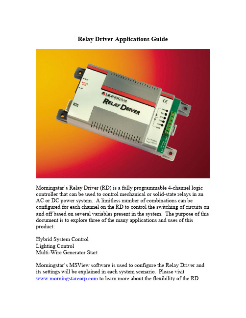
Relay Driver Applications GuideMorningstar’s Relay Driver (RD) is a fully programmable 4-channel logic controller that can be used to control mechanical or solid-state relays in an AC or DC power system. A limitless number of combinations can be configured for each channel on the RD to control the switching of circuits on and off based on several variables present in the system. The purpose of this document is to explore three of the many applications and uses of this product:Hybrid System ControlLighting ControlMulti-Wire Generator StartMorningstar’s MSView software is used to configure the Relay Driver and its settings will be explained in each system scenario. Please visit to learn more about the flexibility of the RD.Hybrid System Control –Alarm Signals and Generator ControlIn this application, the Relay Driver is used to send voltage alarms to a communications device provided by the user at the site. It also will monitor battery voltage and start a generator whenever there is insufficient solar charging from the PV array.The first channel controls the generator. In this particular application, the generator has its own internal warm-up and starting controls. Therefore only a single circuit is needed for the sequence to begin. The generator control mode can be used, but only one wire (the “run” signal) needs to be set up since the generator’s own controls take care of the rest of the start sequence. Two relay channel outputs (channels 2 and 3) are used to signal high and low voltage alarms on the battery bank. This alerts the user of the system (through a spare input on the communications link of their equipment) thatthe battery is higher or lower than the normal operating range due to a fault of some type.Finally, channel number 4 signals if there is a fault with the TriStar controller itself. This may indicate a higher level hardware failure regarding the TriStar’s operation that could not be detected with simple voltage readings. Each of the final channel setups are shown in Fig. 1Fig. 1 Hybrid ConfigurationThe first 3 channels are just threshold settings allowing the relay to be switched on when a certain voltage is met and turned off when that level returns to the normal range. Fig. 2 shows this set up for the gen start (channel 1). The gen start mode allows a delay time to be set for start up and shut down to prevent wear and tear on the generator engine from cycling too frequently.Fig. 2 Voltage Threshold Setup for GenstartThere are several alarms and faults that the TriStar is able to detect using its on-board diagnostics. Any combination of these can be monitored and linked to the Relay Driver so that relays can be opened or closed upon their detection. Fig. 3 shows a list of available faults and alarms. The user simply checks the ones to be monitored by the RD.Fig. 3 TriStar Alarm and Fault SelectionLighting Control – Primary and Secondary Lighting ConfigurationFig. 4 below shows a TriStar with Relay Driver being used in a lighting application for a large off-grid bus stop. The primary load has a ballast that requires a significant surge at startup. For this reason, a mechanical relay provides the most robust way to turn the circuits on and off. This same set up could even be used for applications where a small inverter could power AC lighting loads.Fig. 4 Lighting controlThere are 2 circuits being used. The high-power ballast-controlled lights are connected to the primary circuit, and some smaller low power LED lights are connected to a secondary circuit.The relay driver serves 2 purposes:1. Monitor voltage of the PV array (in conjunction with the TriStar) to activate the lights at night automatically and turn them off in the morning.2. Shut off the primary lights (which draw most of the energy) and activate the low power LED lights during periods of bad weather and low battery state-of-charge.By observing PV voltage (that the TriStar is communicating to the RD via the RJ11 cable) the Relay Driver is able to see when night occurs and will turn the lights on and off accordingly.As can be seen by the wiring, individual lighting circuits can be controlled independently, or all lights can be turned on and off together. Fig. 5 below shows how the PV will turn off all the lights according to night (<8V on the PV panel) and day (>10V on the PV panel). The two lights are tiered so that as battery level gets dangerously low, only low powered LED lighting is used to conserve energy. If the battery gets to a very low level (10.8V) then the LED’s will also be turned off to prevent battery damage.Fig. 5 Lighting Control ThresholdsMulti-Wire Generator StartIn this application there is a generator and battery but no photovoltaic system, and thus no TriStar charge controller in use. The Relay Driver is used in stand alone mode to control the function of a more sophisticated generator start sequence.The first set up is the generator start and stop. In stand alone mode, the Relay Driver accomplishes this with battery voltage readings (taken at its own power terminals) as shown in Fig 6.Fig. 6 Battery ThresholdsIf a generator does not offer its own control for more sophisticated timing, the different channels of the relay driver can be configured to switch each of the control wires required to run a generator. Since this is a diesel generator, a pre-heat function is needed to warm the glow plug briefly before attempting to turn on the engine (accomplished by channel 1). The second phase of starting requires that the run and ignition signals are activated at the same time (channels 2 & 3). Crank Delay is the amount of time that takes place after Pre-Crank but before the engine turns on. Fig. 7 shows a close-up of the starting cycle that the RD will go through once the low battery voltage level is reached.Fig. 7 Generator Starting CycleA maximum run time can be set in the case of a complication in which the batteries are not fully charged. These time limits are shown in Fig. 8.Fig. 8 Max./Min. Run TimesConclusionIn addition to the above examples, many other types of logic are possible. Up to 750mA of current can be drawn on each channel, meaning multiple relays can run off each channel output. Also, relays may be wired in such a way that only combinations of conditions on multiple channels would activate a relay. This gives the user Boolean logic control over the system if desired.Three of many possible scenarios that utilize the Morningstar Relay Driver were discussed in this document. Others include:-Diversion control for wind or hydro systems.-Temperature based control using the RD’s internal temp sensor or the TriStar’s optional Remote Temperature Sensor placed at the battery bank.-Pump control using battery based, direct PV or generator based systems with float control switches monitored by the Relay Driver.To learn more about the Relay Driver’s options, please download MSView from the Morningstar company website at The RD setup wizard in MSView may be explored freely without the RD hardware.。
SIR4中文说明书中文图最终版 (1)

高频电源安装操作运行维护手册
目录
1. 概述 .................................................................................................................................................................. 9 1.1. 型 号 .................................................................................................................................................... 10 1.2. SIR: 静 电 除 尘 器 控 制 装 置 系 列 的 一 员 ....................................................................................... 10
4. 电气数据 ........................................................................................................................................................ 26 4.1. 概 述 .................................................................................................................................................... 26 4.2. 电 源 电 流 ........................................................................................................................................... 27 4.3. 要 求 的 电 缆 ....................................................................................................................................... 27
4r执行力系统

内部资料 严禁拷
21
TSE员工创富
4R能够给成长型企业带来的6个价值
1
个人战略支点
2
执行文化
通过从高层入手,挖掘个人成长过程中的闪光点,帮助梳理个人战略计划, 把员工个人成长和公司成长结合起来,啊个人战略和公司战略结合起来,
让员工愿意与公司“走下去”
通过灌输客户价值和结果导向意识,创造良好氛围,培养员工结果思维和 习惯推动贵公司建立“人人谈客户,处处要结果”的执行文化
1、业绩跟踪报表体系
2、月季年度活动会议
3、行动改进
详细 说明
建立报表系统 收集与目标相关的数据 准备业绩报表
抓出关键行动因素 确定关键业绩指标 落实关键业绩指标 设定权重
定义改进指标的关键失败因素 指定改进行动计划 落实改进行动计划
发现问题、决解问题、数据处理
确保目标实现、优化管理
TSE——没有员工的成长就没有企业的成长
TSE员工创富
R1-结果定义:门从哪儿开,人从哪儿走!
● 酒店一定是现有对客户价值定义,才有服务生细 致,周到的服务和对流程的坚守 ● 结果定义改变员工行为,基于客户价值的结果定 义是执行的起点
• 不同的门,不同的目的,自然是不同的结果!
TSE——没有员工的成长就没有企业的成长
内部资料 严禁拷
1
TSE员工创富
神秘客人制度
TSE——没有员工的成长就没有企业的成长
内部资料 严禁拷
10
TSE员工创富
R3的前提是“我不相信”
R3的功能:就是制止“魔 鬼”。
在制止“魔鬼”里面,人们 只会做你检查的,不会做你 希望的。 案例:检查-抽查-自检-免检
TSE——没有员工的成长就没有企业的成长
AS400服务器日常维护操作手册

AS400服务器日常操作手册1、IPL 设置(服务器启动设置)1)版面设置为:01 B N V=F第一部分表示目前状态,01表示显示状态, 02表示修改状态;第二部分B 表示起机资源为硬盘区,D 表示从光驱启动系统;第三部分N 表示自动启动, M 表示手动启动;第四部分 V=F 表示快速启动, S 表示慢速启动(为了在启动时对系统部件进行全面检测)2)控制版面操作:在正常启动状态时:01 B N V=F在手动起机状态时:01 B M V=F在安装操作系统时:01 D M V=F光盘启动操作系统时:01 D M V=F3)关机命令:PWRDWNSYS *IMMEDGo power 3 44)非正常状态下手动关机:版面设置由01 B m V=F 改为 02 B M V=F 再改为 01 B M V=F 按电源钮,这时出现 0?,确定后即可关机。
再次启动时再改回自动模式。
2、基本CL命令:1)显示 AS/400 的磁盘容量和使用状况:DSPSYSSTS “显示系统状态”➢显示用户简要表:DSPUSRPRF 察看用户情况➢操作用户简要表: WRKUSRPRF➢创建用户: CRTUSRPRF2)关机:GO POWER,选择3,F16 (shift+F4)直接关机;选择4,F16 关机后重启动。
立即关机命令:PWRDWNSYS *IMMED➢如果不知道如何正确拼写一d➢查找命令 GO CMD*** (*为相关命令中的字符)在输入命令的参数时,有两种方法可以获得帮助提示信息:➢在命令名前加一个问号,如?DSPOBJD➢在输入命令名后按下F4键,如 DSPOBJD(F4)3)处理信息命令➢更改信息通知命令:CHGMSGQ可以自己制定消息发到哪个消息队列中➢打印消息队列中的信息命令:DSPMSG MSGQ(消息队列名称) OUTPUT(*PRINT)➢将信息发给所有在线用户命令:SNDMSG TOUSR(*ALLACT)注:所有当前在线用户都会收到该消息,用户切换到他自己的消息队列中即可看到该消息。
- 1、下载文档前请自行甄别文档内容的完整性,平台不提供额外的编辑、内容补充、找答案等附加服务。
- 2、"仅部分预览"的文档,不可在线预览部分如存在完整性等问题,可反馈申请退款(可完整预览的文档不适用该条件!)。
- 3、如文档侵犯您的权益,请联系客服反馈,我们会尽快为您处理(人工客服工作时间:9:00-18:30)。
• 注:该命令的作用,将quickstart 项目生成为普通 elipse项目,这样就可以在eclipse中导入(import) 了。
• • • •
进入
4)初始化数据库(使用默认的 H2 database)
springside-springside4-V4.0.0.GA-2-g4fb1044\springside-springside44fb1044\examples\quickstart 目录 运行: mvn antrun:run -Prefresh-db
• @SequenceGenerator(name="SS_SEQ",sequenceName="SS_SE Q_USER", allocationSize=20)
• (2)采用Table,建表语句:create table QTY_W_GENERSEQ(GEN_KEY VARCHAR2(50) not null,GEN_VALUE INTEGER) • @Id
1、准备工作
• 1)安装jdk 1.6 以上版本,设置 JAVA_HOME,PATH JAVA_HOME=D:\Program Files\Java\jdk1.7.0_05 在系统PATH中添 加;%JAVA_HOME%\bin
• 2)安装maven,设置M2_HOME,PATH 如: M2_HOME=D:apache-maven-3.0.4 在系统环境 变量PATH中添加;%M2_HOME%\bin • 3)Eclipse,并安装maven插件m2-eclipse
• 6)修改项目application.properties中数据库连接配置。 • 如:
• jdbc.driver=oracle.jdbc.driver.OracleDriver
• jdbc.url=jdbc:oracle:thin:@127.0.0.1 :1521:orcl • ername=resms • jdbc.password=resms
5)运行(使用内嵌的jetty server运行 项目)
• 在eclipse中,右击quickstart中的pom.xml文件 • 选择:Run Configuration
• Base diretory: 选择quickstart项目 • Goals: jetty:run
• 点击run,运行该项目。
•
注意groupId、artifactId、version的写法。
•
5)修改项目中 entity的主键生成策略。
• 1.原来的实体类 extends IdEntity,现在不需要继承IdEntity. • 2.选择所需要的主键生成策略。 • 如: • (1)采用SEQUENCE • @Id
• @GeneratedValue(strategy=GenerationType.SEQUENCE, generator="SS_SEQ")
• @GeneratedValue(strategy = GenerationType.TABLE,generator="ss_user")
• @TableGenerator(name="ss_user",table="springside_ss_generseq" ,pkColumnName="gen_key",valueColumnName="gen_value",pkCol umnValue="ss_user") • @Column(name = "id", unique = true, nullable = false, precision = 10, scale = 0)
2、下载并在Eclipse中运行 qucikstart
• 1)下载 SpringSide4 /download.html •
2)
•
•
运行CMD,进入
springside-springside4-V4.0.0.GA-2-g4fb1044\springside-springside44fb1044\modules 目录
二、连接ORACLE数据库
• 1.项目依赖oracle的JDBC驱动包,而该包不能使用maven从中央仓库中获得,需要手动将该文件装 配到本地仓库中。
•
பைடு நூலகம்
1)下载 ojdbc14.jar包,
•
2)放于 d:\test\ojdbc14.jar
• • •
3)cmd 进入 d:\test,执行maven命令: mvn install:install-file -DgroupId=com.oracle -DartifactId=ojdbc14 -Dversion=10.2.0.1.0 Dpackaging=jar -Dfile=ojdbc14.jar 该命令会将ojdbc14.jar装载到本地maven仓库 \repos\com\oracle 下。
• • •
4)修改项目pom.xml文件关于驱动的依赖配置 <jdbc.driver.groupId>com.oracle</jdbc.driver.groupId> <jdbc.driver.artifactId>ojdbc14</jdbc.driver.artifactId>
•
<jdbc.driver.version>10.2.0.1.0</jdbc.driver.version>
Springside4 运行记录
• 最近在学习springside4,下面是我在eclipse 中运行springside4 demo过程,希望给大家 参考一下,不正确的地方,希望大家能指 出,同时,我也有很多困惑之处也在改贴 中请教大家。
• 一、在Eclipse 中运行SpringSide4的demoqucikstart • (参看: https:///springside/springside4/ wiki/QuickStart)
•
注:可CMD进入springside-springside4-V4.0.0.GA-2-g4fb1044\springside-springside44fb1044\support\h2目录
•
• •
运行:
mvn exec:java 对本地的H2数据库进行管理(用户:sa 密码:(为空)) 本地H2数据库文件位置: C:\Users\用户名\.h2
•
运行:mvn install
•
注:该命令的作用,将所有module编译打包安装到Maven的本地仓库。
3)运行CMD,进入
• springside-springside4-V4.0.0.GA-2g4fb1044\springside-springside44fb1044\examples\quickstart 目录 • 运行:mvn eclipse:eclipse