Comparison of different DC voltage supervision strategies in a local
单介质和双介质阻挡放电低温等离子体降解甲苯的比较
文章栏目:大气污染防治DOI 10.12030/j.cjee.201906002中图分类号 X511 文献标识码 A于欣, 党小庆, 李世杰, 等. 单介质和双介质阻挡放电低温等离子体降解甲苯的比较[J]. 环境工程学报,2020, 14(4): 1033-1041.YU Xin, DANG Xiaoqing, LI Shijie, et al. Comparison of single and double dielectric barrier discharge non-thermal plasma for toluene removal[J]. Chinese Journal of Environmental Engineering, 2020, 14(4): 1033-1041.单介质和双介质阻挡放电低温等离子体降解甲苯的比较于欣,党小庆*,李世杰,黄准,郭惠,张金龙西安建筑科技大学环境与市政工程学院,陕西省环境工程重点实验室,西安 710055第一作者:于欣(1993—),女,硕士研究生。
研究方向:大气污染物治理。
E-mail :187********@ 摘 要 为研究介质阻挡放电(DBD)反应器结构对低温等离子体降解甲苯的影响,设计了具有单层介质和双层介质的DBD 反应器。
对2种反应器的放电特征、甲苯去除率、矿化率、CO 2选择性和能量效率进行了比较,并对施加电压和初始浓度对甲苯降解效果的影响进行了分析。
结果表明:在相同电压下,双介质反应器(DDBD)具有更高的电场强度,而单介质反应器(SDBD)的输入功率更高;当甲苯浓度和电压分别为616、1 027、1 848 mg·m −3和14~24 kV 时,双介质中的甲苯去除率为9.4%~100%、7.4%~99%、5.1%~64%,单介质为67%~98%、46%~90%、26%~59%。
这说明低电压下单介质反应器的甲苯去除率更高,而高电压下则相反,并且,浓度降低、电压升高有利于甲苯的降解。
腾讯NDA限制-腾讯NDA限制-Jacinto6Eco SoC电源解决方案-DRA72 TDA2

TPS22965 + TPS51200
8
New PDN Concept
0.40 = $3.25
(3 AVS @ 1‐2.5A, Dual 1.8/3.3V IO, DDR3L)
18 + 4 + 4.6 + 4.6 + 4 + 9 = 44
$4.42 128 $2.53 74
$7.32 190 $4.64 119
5. “PDN’s AVS Capability” is the achievable power if all AVS power rails are increased to 90% of capacity while other power rails remain at typical Use Case modelled values.
(3 AVS @ 1‐3.5A, Dual 1.8/3.3V IO, DDR3L) (similar to EVM PDN #0)
49 + 9 + 4 = 62
#8.2 – LP87524 + LP5912 + TLV713 + LP5907 +
9.92
1.26 + 0.19 + 0.07 + 0.10 + 0.10 +
2. PDN Support component (Rs, Cs & Ls) pricing from Mouser Distribution website using single 4k – 10k/reel qty costs as of May 2016. Both PDN Support & PDN Total Costs have been provided for relative comparison only, individual customer volume pricing may vary.
胸部外伤英文

Blunt chest injury
Surgical requirement not so often
Late death, mainly from circulatory respiratory insufficiency
4. Principle of diagnosis and treatment
Rib
mediastinal pendelluft
Fracture Intercostal vessel —Hemothorax ——ventilation,
lung compression, blood loss
Lung tissue —Pneumothorax —ventilation, lung
4.1 Concept of time-effect
Time-effect:
• Time and outcome of trauma progress • Time and effect of diagnosis and management • Golden hour
4.2 Diagnosis
• According to variety of violence
Penetrating chest injury Blunt chest injury
• According to whether there is any communication between pleural cavity and atmosphere
Variety of trauma, mechanism of damage, time course after injury, vital signs
Evaluation of trauma
两种 DC-DC 转换器原理产生的噪声特性比较
两种 DC-DC 转换器原理产生的噪声特性比较Robert Marchetti,高级产品经理Vicor 公司,美国 Andover,MA目前,大部份的 DC-DC 转换器己普遍以高频率的开关技术为基础。
而在开关转换器中,有效的高频率开关一直被视为模块功率密度大小,性能表现优劣的关键。
开关频率高,所用的磁性元件和电容愈小,反应时间更快,噪声更低,滤波要求较小。
尽管 DC-DC 转换器所产生的噪声是比之前改善了,但是所有 DC-DC 转换器还是会产生 EMI 或者其它噪声的。
而所产生的噪声水平,不论是共模的,差模的或者是辐射噪声,会因为不同的生产厂,或者是采用不同的转换方法而产生很大的差异。
虽然市面上有上百种的 DC-DC 转换器,各有不同的设计和拓扑结构,大体可以归为两大类: 固定频率的脉宽调制式 (PWM) 和变频的准谐振零电流开关(ZCS) 两种。
设计师在选择 DC-DC 转换器时必须先了解两种原理的噪声表现。
脉宽调制式 (PWM) 模块由于不能够解决开关损耗问题,故此,它需要在工作效率和开关效率间作取舍。
开关元件在瞬时导通和关断时,使电感电流产生不连续性的状态,因而产生热量和噪声。
由于功耗来自开关损耗,它会随着脉宽调制式模块的开关频率增高而增大,直至它变为一个显著的耗损成因,达到了那一点,效率会迅速减低,开关元件所承受的热及电气应力变得无法处理。
这种开关损耗的属性,变为开关频率障碍,限制了转换器提升功率密度的能力。
除了所产生的噪声有差别,另一个脉宽调制式与零电流/零电压开关技术的分别是准谐振转换器的波形是一正弦波,而不是脉宽调制式的方波。
由于电流的波形没有近乎垂直上升和下降的尖削部份,减少电抗组件的应力,减低寄生噪声。
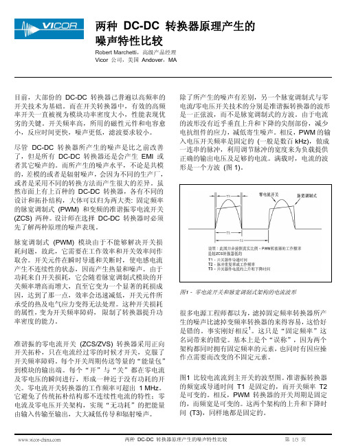
相反,PWM的输入电压开关频率是固定的(一般是数百kHz),做成一连串的脉冲,利用调节脉冲的宽度来为负载提供正确的输出电压及足够的电流。
满载时,电流的波形是一个方波(图1)。
!图1 - 零电流开关和脉宽调制式架构的电流波形!很多电源工程师都以为,滤掉固定频率转换器所产生的噪声比滤掉变频率转换器的来得容易,这恰好是错的。
重组质粒构建

P1及YAC载体
酵母人工染色体,可容纳外源基因片 段长达200kb-1000kb,含有酵母第4号染色 体的着丝粒和自主复制序列CEN4、ARS1 ,作为端粒的Tel序列,选择性标志URA3 、TRP1和SUP4,能在酵母中稳primary) 工具酶:限制性内切酶
连接酶
常见的基因工程载体
载体:用于携带重组DNA,并且能够使外源DNA一起 复制与表达的运载工具。
❖ 根据来源:plasmid; phage; viral; BAC; YAC
❖ 根据用途分:克隆载体;原核生物表达载体;真核 生物表达载体
噬菌体载体
❖ λ噬菌体(λphage)
外源DNA:9~23kb 常用:EMBL 系列、 λgt 系列、charon系
列
❖ 粘性质粒(cosmid): λDNA的 cos区+质 粒,双链环状DNA,克隆容量: 40~50kb
❖ M13噬菌体
λ噬菌体(λphage)
特点:一种能感染大肠杆菌的病毒, 野生型为双链线状DNA分子,长度48.5kb, 分子两端各有一个12bp组成的粘性末端, 感 染大肠杆菌后,线状DNA通过粘性末端互补 连接成环, 连接处称COS位点。
例:
干扰素是治疗癌症的重要物质,人血液中每升只能提取 0.05μg干扰素,因而其价格昂贵。但美国有一家公司用遗 传工程方法合成了价格低廉、药性一样的干扰素,其具体 做法是:
从人的淋巴细胞中提取能指导干扰素合成的基因,并使之 与一种叫做质粒的DNA结合,然后移植到酵母菌内,从而 用酵母菌来产生干扰素。
❖ 通常质粒含有某些染色体没有的基因,负责 编码某些功能蛋白,这些功能并不是细菌生 存所必需的,但在一定环境下,可对细菌宿 主的生存有利。由质粒产生的表型包括对抗 生素的抗性(R因子)、产生抗生素、降解复 杂有机化合物、产生大肠杆菌素(大肠杆菌 素因子col)、肠毒素及限制酶、修饰酶等。
低噪声放大器 LNA Highly linear wideband low power current mode LNA
II. WIDEBAND LNA DESIGN
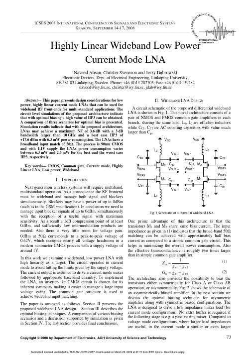
A circuit schematic of the proposed differential wideband LNA is shown in Fig. 1. This novel architecture consists of a pair of NMOS and PMOS common gate amplifiers in each branch, sharing the same load. L1, L2 are off-chip inductors while CC1, CC2 are AC coupling capacitors with value much larger than Cgs.
DESIGN OF INTEGRATED CIRCUITS AND MICROSYSTEMS
output signal power can be achieved by allowing a larger current to the load. Obviously, in either case the limitation is the supply voltage VDD . So the signal power can be larger in the current mode, i.e. for a lower load resistance since
ห้องสมุดไป่ตู้
transistors either symmetrically for Class A or Class AB
operation, or asymmetrically. Fig. 2 shows the schematic of
an asymmetrically biased amplifier. In the next section we
comparison of various ion exchange resins

A comparison of various ion exchange resins for the removal of ferric ions from copper electrowinning electrolyte solutions Part II:Electrolytes containing antimony and bismuthBethan McKevitt a ,⁎,David Dreisinger ba Vale Inco Limited,CanadabUniversity of British Columbia,Canadaa b s t r a c ta r t i c l e i n f o Article history:Received 19December 2008Received in revised form 7April 2009Accepted 7April 2009Available online 16April 2009Keywords:Ion exchangeCopper electrowinningFour commercially available ion exchange resins were tested to compare their ability to remove ferric from copper electrowinning electrolytes containing antimony and bismuth.Ion exchange batch tests were per-formed in the initial phase of the study and indicated that all resins tested co-loaded some antimony with the ferric.The aminophosphonic resin tested was the only resin to load a signi ficant amount of bismuth.Further investigation was performed with the sulphonated monophosphonic resin,Purolite S957.Results were inconclusive as to whether antimony would continue to load onto the resin with time or whether the antimony would eventually reach an equilibrium loading on the resin.Antimony stripping was shown to be possible using a solution containing sulphuric acid and sodium chloride,indicating that ferric ion exchange is a technically feasible process for removal of iron from copper electrowinning electrolyte solutions containing antimony and bismuth.©2009Elsevier B.V.All rights reserved.1.IntroductionIn Part I of this work,the ability of four commercially available ion exchange resins containing a phosphonic acid group were evaluated for the removal of ferric iron from a synthetic copper electrowinning electrolyte solution.Most copper electrowinning operations utilize solvent extraction ahead of the electrowinning tankhouse to minimize the impurities present in the electrolyte solution.However,in a re finery where solvent extraction is not used,signi ficant amounts of other im-purities,such as antimony and bismuth,can be present in the elec-trolyte.For example,at the Vale Inco copper electrowinning facility in Copper Cliff,electrolyte puri fication is achieved without solvent extraction,and consequently the impurity levels in their electrolyte are fairly high (Sabau and Bech,2007).While the presence of antimony,and bismuth in a copper electro-winning electrolyte is unusual,these impurities are quite common in copper electrore fining electrolytes.In copper electrore fining,these impurities often contaminate the copper cathode product and so their levels in electrolyte must be controlled (Wang,2004).Ion exchange is one option available for the removal of these impurities.In a compre-hensive study of several ion exchange resins,Unitika's UR-3300and Rohm and Haas'DUOLITE C-467resins were found to have the best selectivity for removal of antimony and bismuth from copper electro-re fining electrolytes (Dreisinger and Leong,1992).Loading of bismuth and antimony onto the resin can be described by Eqs.(1)and (2):Bi 2ðSO 4Þ3þ6ðHR Þ→2ðBiR 3Þþ3H 2SO 4ð1ÞSb 2ðSO 4Þþ6ðHR Þ→2ðSbR 3Þþ3H 2SO 4:ð2ÞIn Dreisinger's study,elution was performed using hydrochloric acid and can be described by Eqs.(3)and (4):2ðBiR3Þþ6HCl →2BiCl3þ6ðHR Þð3Þ2ðSbR 3Þþ6HCl →2SbCl 3þ6ðHR Þ:ð4ÞAs an alternative to using hydrochloric acid,elution schemes with solutions containing sulphuric acid and sodium chloride have been proposed (Fukui et al.,2000).This approach is advantageous from a practical standpoint since many copper re fineries already have sulphuric acid and sodium chloride readily available on-site.This allows for the creation of hydrochloric acid according to Eq.(5):H 2SO 4þ2NaCl →Na 2SO 4þ2HCl :ð5ÞIt is important to note that both resins shown by Dreisinger to have excellent removal capability to remove antimony and bismuth are aminophosphonic resins.Also note that the synthetic solutions tested contained no ferric,and no sulphonated phosphonic resins were included in the study.In a later study,UR-3300and C-467were loaded with a commercial copper electrore fining electrolyte containing antimony,bismuth,andHydrometallurgy 98(2009)122–127⁎Corresponding author.E-mail address:Bethan.McKevitt@ (B.McKevitt).0304-386X/$–see front matter ©2009Elsevier B.V.All rights reserved.doi:10.1016/j.hydromet.2009.04.007Contents lists available at ScienceDirectHydrometallurgyj o u r n a l h o me p a g e :w w w.e l s ev i e r.c o m/l o c a t e /hyd ro m e tiron.Some iron loading was observed on both resins;however this could be eliminated by pre-reducing any ferric to ferrous by first passing the solution over a bed of copper wire.Loading of antimony and bismuth on both resins was improved when the ferric was pre-reduced to ferrous (Dreisinger and Scholey,1995).Since the presence of ferric is known to affect the ion exchange removal of antimony and bismuth with aminophosphonic resins,it is likely that the presence of antimony and bismuth could affect the removal of ferric by ion exchange with a resin containing the phosphoric acid group.This work focuses on the ability of four commercially available ion exchange resins containing the phosphoric acid group to remove ferric from a copper electrolyte solution containing antimony and bismuth.2.ExperimentalAs in the work in Part I,four commercially available resins were tested:Eichrom Diphonix (sulphonated diphosphonic),Purolite S957(sulphonated monophosphonic),Generic D416(sulphonated mono-phosphonic),and Lanxess Lewatit MonoPlus TP-260(aminophospho-nic).It is important to note that all these chelating resins contain the phosphoric acid group.In addition to the phosphoric acid group,the aminophosphonic resin also contains a group from the amine family;the sulphonated monophosphonic resins contain the sulphonic acid group;and the sulphonated diphosphonic resin contains both the sulphonic acid group and a carboxylic acid group.Note that the pH of the solutions tested in this work is suf ficiently low that the carboxylic acid group,typical of a weak acid exchanger,is not expected to have any impact on results.Sketches illustrating the chemistry of these chelating resins can be found in Fig.1of Part I of this work.Prior to testing,all resins were conditioned to ensure that each resin was in the acidic (H +)form and all volumes reported are based on the acidic form of the resins.To gain a qualitative comparison of the performance of the four resins,equilibrium loading experiments were performed.A test set was performed for each resin in which a series of flasks containing different electrolyte to resin volume ratios were placed in an orbital shaker at 175rpm and 55°C for 24h.For each test set,a synthetic electrolyte solution was prepared by adding the following reagents to water:sulphuric acid,copper sulphate,nickel sulphate,cobaltous sulphate,ferric sulphate,bismuth trioxide,antimony sulphate,and arsenic pentoxide.Heat was added to this solution in an attempt to dissolve all reagents;however,in all cases there was a small amount of residual solids left so the synthetic electrolyte was filtered before use.Temperature was not monitored during this procedure,and is believed to be the reason for fluctuations in feed chemistry between test sets.It should be noted that the 24h is believed to have been more than enough time to reach equilibrium since a series of tests run withVale Inco plant electrolyte reached equilibrium within 8h for a volume ratio of 14:1(mL electrolyte to mL resin).Based on the results of this first set of scoping tests,the optimum resin type was selected for further testing.The next set of tests performed involved further equilibrium batch loading tests with a volume ratio of 100:1(mL electrolyte to mL resin).In these tests the amount of ferric added to the various flasks was varied in order to produce different iron to antimony ratios in the synthetic electrolyte solution.An extended column loading test was performed to determine if antimony or iron would displace the other element off the resin.In this test,130BV of a synthetic electrolyte was passed over the resin.Note that the synthetic electrolyte for this test was prepared with a similar chemistry as used in the batch equilibrium tests,but otherwise followed the column loading procedure reported in Part I of this work.Next,antimony elution tests were performed by loading two columns,each containing 10mL of resin,with 150BV of a solution containing sulphuric acid and saturated in antimony at a rate of 15BV/h.Stripping of both columns was performed at 50°C.The first column was stripped with a solution containing only sulphuric acid while the second column was stripped with a solution containing both sulphuric acid and sodium chloride.Finally,repeated cycle testing was performed on a single sample of Purolite S957resin.In these tests,antimony was added to both the loading and stripping electrolyte,in order to observe how antimony loading affects the resin performance over a few cycles.Ten cycles of loading and stripping were performed,followed by a column wash consisting of 50BV of solution containing sulphuric acid and sodium chloride.A final cycle of loading and stripping was performed to deter-mine whether this wash had been able to restore the performance of the ion exchange resin.It should be noted that challenges were encountered obtaining accurate antimony assays in the solution samples.All samples were analyzed at the Vale Inco Central Process Technology Laboratory in Copper Cliff,Ontario.Solution metal concentrations were determined using an in-house inductive coupled plasma procedure:ICP-PMET.In order to ensure that these results were accurate,resin loadings for the 100:1volume ratio from the first set of batch tests were deter-mined by both a mass balance using the solution assays and by resin digestion.Results showed good correlation for all elements except antimony.Therefore,for subsequent tests,the amount of antimony present in solution was determined using ICP-MS,which was found to correlate very well with resin digestion results.Resin analysis involved completely dissolving a known mass of resin in nitric acid using microwave digestion.The resulting solution was then analyzed using a standard ICP analysis and results were reported in mg/g resin.This could then be correlated back to the initial volume of resin to obtain values of mg/mL resin.Note that no antimony or bismuth was detected in samples of conditioned,unloaded resin (i.e.resin blanks)and only minimal amounts of iron (b 0.2mg Fe/mL resin)were present.3.Results and discussionThe results for the various tests are discussed in following subsections.3.1.Equilibrium loading experimentsThe composition of the synthetic electrolyte feed solutions for the various tests is displayed in Table 1.It should be noted that there is some fluctuation in the concentration of the metals in the feed solution between each tests set.This is believed to be due to the fact that temperature was not monitored during electrolyte preparation.However,since the purpose of these tests was to gain a qualitative comparison between the overall performance of the various resins,and was not meant to be a quantitative analysis of resinselectivities,Fig.1.Ferric loading curves,equilibrium loading tests.123B.McKevitt,D.Dreisinger /Hydrometallurgy 98(2009)122–127these fluctuations in feed chemistry were deemed acceptable for this work.Note that the tests were all run at approximately 220g/L acid.The loading curves for ferric and bismuth are shown in Figs.1and 2,respectively.The loading curve plots the amount of an element loaded on the resin against the volume ratio of electrolyte to resin.Note that there is no loading curve for antimony since the solution samples were only run using ICP-PMET,and not by ICP-MS.All samples with a volume ratio of 100:1were also analyzed by resin digestion,and the results from resin digestion are displayed in Fig.3.Fig.1shows that the ferric loading capacity of the sulphonated monophosphonic resins (Purolite S957and Generic D416)and the aminophophonic resin (Lewatit TP 260)are very similar at ~23mg Fe/mL resin,while the capacity of the sulphonated diphosphonic resin (Diphonix)is substantially less at ~14mg Fe/mL resin.The only exception is that the calculated iron loading for the Generic resin is ~30mg Fe/mL resin at a volume ratio of 100:1.This is believed to be due to an erroneous assay result as the resin digestion results for this sample,presented in Fig.3,shows that the total iron loaded onto the resin was ~25mg Fe/mL resin.These ferric loading capacities are similar to the ferric loading obtained in the column experiments in Part I of this work.Fig.2shows that the aminophosphonic resin (Lewatit TP 260)loaded a signi ficant amount of bismuth.In fact,these results show that at a volume ratio of 100:1,more bismuth was loaded than ferric,illustrating why aminophosphonic resin are often used for bismuth removal from copper electrore fining electrolytes.The resin digestion results in Fig.3show that all resins loaded some antimony.These results also show that the sulphonated monopho-sphonic resins (Purolite S957,Generic D416)loaded similar amounts of antimony as the aminophosphonic resin (Lewatit TP 260).While the amount of antimony in the feed solution was signi ficantly lower for the aminophosphonic resin,the Fe/Sb ratio in the feed was approximately 12,while the Fe/Sb ratio for the sulphonated monophosphonic resins was between 7and 8.As will be seen in Section 3.2,the amount of antimony loaded on Purolite S957(sulphonated monophosphonic)does not appear to vary signi ficantly above an Fe/Sb ratio of about 2.This suggests that the sulphonated monophosphonic resins may be as useful as the aminophosphonic resins for antimony removal;further work should be performed to further compare these two resin types with respect to antimony removal.Additionally,Fig.3shows the resin loadings for arsenic,copper,nickel,and cobalt.All resins appear to have loaded similar amounts of arsenic.It is interesting to note that the sulphonated diphosphonic resin (Diphonix)loaded the most copper,nickel,and cobalt while the aminophosphonic resin (Lewatit)loaded the least amount of these elements.Since the sulphonic acid group allows for non-selective cation extraction at low pH,it makes sense that the aminophosphonic resin loaded the least amount of these elements since this resin is the only resin tested that does not contain the sulphonic acid group.Since the sulphonated disphosphonic resin loaded the most copper,nickel,and cobalt while loading the least amount of iron,this may suggest that the ratio of sulphonic acid groups to phosphoric acid groups is higher in this resin than for the sulphonated monophosphonic resins tested.Based on the results from these initial equilibrium batch loading tests,the sulphonated monophosphonic resins appear to be better suited than the sulphonated diphosphonic resin or the aminopho-sphonic resin for ferric removal in the presence of antimony and bismuth.Therefore,the Purolite S957resin was selected for further testing.3.2.Effect of iron to antimony ratioA second series of equilibrium batch tests were performed with the Purolite S957Resin.The composition of the feed solutions for the flasks can be found in Table 2.At the end of the test,all resin samples were digested and analyzed.Since flasks “F ”and “I ”contained approximately the same amount of iron,and only flask “F ”contained antimony,comparing the results from these two tests gives an indication of how the presence of antimony may affect the loading of iron onto the resin.The resin loading for the flask without any antimony present (“I ”)was 30.6mg Fe/mL Resin,while the flask with antimony present (“F ”)loaded slightly less iron:27.6mg Fe/mL Resin.This suggests that the loaded antimony is taking up ion exchange sites that could have been available forferric.Fig.2.Bismuth loading curves,equilibrium loading tests.Table 1Feed composition of synthetic electrolyte for equilibrium loading tests.g/L Cu Ni Co As Fe Sb Bi Diphonix 33.013.610.0 2.6 2.00.120.29Generic 35.414.410.8 2.9 2.20.290.38Lewatit 37.015.211.6 2.8 2.30.190.46Purolite38.815.612.02.92.30.290.44Fig.3.Resin digestion results,equilibrium loading tests.Table 2Feed composition of synthetic electrolyte for ratio tests.g/L Fe(III)Sb Fe /Sb Cu Ni Co As Bi “A ”b 0.010.220.0041.610.49.5 2.70.36“B ”0.130.220.5940.610.39.4 2.70.37“C ”0.230.23 1.040.610.29.3 2.70.35“D ”0.410.23 1.839.410.09.2 2.60.33“E ”0.860.24 3.641.210.59.6 2.70.38“F ” 2.100.258.440.610.29.4 2.70.37“G ” 4.280.251741.610.59.6 2.70.38“H ”8.680.243641.010.59.6 2.70.39“I ”2.10b 0.01∞39.215.211.22.70.15124 B.McKevitt,D.Dreisinger /Hydrometallurgy 98(2009)122–127Resin loadings at the various iron to antimony ratios are plotted in Fig.4.This graph shows that in a solution with no iron present,the resin loaded the most antimony.It also shows that the amount of antimony loaded onto the resin decreased at a fairly steady rate,indicating that iron was competing favourably with the antimony,until the iron/antimony ratio reached a value of 1.75.From this point on,the amount of antimony loaded onto the resin only decreased very slightly as the iron/antimony ratio continued to increase,indicating that increasing the iron to antimony ratio beyond 1.75has very little affect on the antimony loading.Note the extremely low antimony loaded at an iron/antimony ratio of 17.This is believed to be due to an assay error as there is no evidence of a lower concentration of antimony present in the solution sample at the end of this test.Unfor-tunately,there was insuf ficient resin available to re-assay this sample.3.3.Extended loading:displacement testAn extended column loading experiment,with the feed composi-tion shown in Table 3,was performed to determine whether antimony or iron would displace the other element from the resin.Displacement of an element can be seen from a loading curve that plots C/C 0of the elements in the solution exiting the column.While an element is being loaded onto the resin,the C/C 0value will be b 1.If there is no interaction between the element and the resin,the C/C 0value will remain at 1.If an element is being displaced from the resin,the C/C 0value will be N 1.The loading curve from the displacement test is plotted in Fig.5.This graph shows a single point where the iron sample appears to have a C/C 0greater than one;however,this is likely due to assay error as there is no evidence of antimony loading on the resin at this point on the curve.Note that the breakthough point for antimony is signi fi-cantly later in the loading cycle than for iron.This suggests that the resin may be selective for antimony over iron.3.4.Antimony elutionThe composition of the feed solutions for both loading and elution of antimony from the Purolite S957resin can be found in Table 4.A mass balance using the solution samples indicate a resin loading of 43.6mg Sb /mL resin in Test 1,and 41.4mg Sb /mL resin in Test 2.The detailed loading curve from test 1is shown in Fig.6.This curve shows that at the end of the loading tests,the resin was not fully loaded with antimony since C/C 0never reached 1.Using the assays from the stripping samples,the cumulative per-cent antimony eluted from the resin was calculated for each sample from the stripping test.These results are plotted in Fig.7.This figure shows that antimony is eluted slowly in the presence of sulphuric acid alone (the reverse reaction of Eq.(2),and it is eluted very quickly in the presence of a solution containing both sulphuric acid and sodium chloride (Eq.(4)).Further testing would be required to determine whether or not complete stripping could be attained with a solution containing only sulphuric acid.It should be noted that as the stripping test with the solution containing sodium chloride started,a white precipitate was observed in the strip solution.This precipitate subsequently redissolved by the time 5BV of solution had been collected.The white precipitate was not sampled,but it is possible that SbOCl may have formed,since the initial sample of strip solution collected would have had low acidity due to displacing the deionized water remaining in the column from the load wash step.This reaction could be described by Eq.(6):SbCl 3þH 20→SbOCl ðs Þþ2HCl :ð6ÞThis result suggests that flushing the ion exchange bed with water prior to a wash with sulphuric acid and sodium chloride may not be desirable as it may lead to SbOCl precipitation in the ion exchange bed.Further work would be required to test this hypothesis.3.5.Repeat column cycle testingThe composition of the feed and stripping electrolyte used in each cycle of these tests can be found in Table 5.To determine whether the iron loading performance of the resin was signi ficantly impacted by the presence of antimony in electrolyte,a solution mass balance was performed to determine the amount of iron loaded and the amount of iron stripped for each cycle.These results are plotted in Fig.8.This graph shows that the amount of iron loaded onto the resin stayed approximately constant over the course of the tests,suggesting that the effect of antimony on iron loading is not deleterious over ten cycles.Note that the total amount of iron loaded in these tests (typically 20–21mg Fe/mL resin),is approximately the same as the values obtained in Part I,for the Purolite tests performed with no antimony present (20–22mg Fe/mL resin).Also note that there is signi ficantlymoreFig.4.Iron and antimony loadings at various Fe/Sb ratios.Table 3Feed composition of electrolyte for column displacement test.g/LCu Ni Co As Fe Sb Bi Displacement test39.213.610.92.52.10.180.33Fig.5.Displacement test loading curve.Table 4Feed composition of electrolyte for antimony elution test.g/L H 2SO 4Cu Fe(III)Sb Na Load 1219.30.00.00.450.0Load 2218.50.00.00.470.0Strip 1177.80.00.00.000.0Strip2169.90.00.00.0079.2125B.McKevitt,D.Dreisinger /Hydrometallurgy 98(2009)122–127scatter in the mg Fe/mL resin calculated from the loading mass balance than the stripping mass balance,likely indicating sampling error of the fully loaded solution.To more precisely determine the effect of antimony on iron loading,the stripping time required was plotted against cycle time.As in Part I,stripping time was de fined as the time required to reach an ORP of 500mV SHE .The plot of stripping time against cycle number is found in Fig.9.In this graph,the stripping time tends to decrease with cycle number,for cycles 1through 10.This suggests that the antimony is loading onto the resin,thus reducing the number of sites available for iron to load.Although there is only one data point after the salt wash,the stripping time did increase in cycle 11,suggesting that after the antimony is removed,ion exchange sites may once again be freed up to load more iron.It is interesting to note that the results from cycle 3and cycle 6fall signi ficantly off the general trend line.During cycle 3,the loading cycle was not stopped after 8h (approximately 80BV),and 110BV of loading solution were passed over the resin.The fact that this cycle took longer to strip may be an indication that the resin was not fully loaded after 8h.The reason for cycle 6stripping much sooner than expected is unknown.It may be that some of the cuprous from the previous stripping cycle formed copper powder and found its way into the ion exchange column.The mass balance for this test does not give any indication that this occurred;however if this were to have happened,then less iron would have loaded onto the resin since some of the ferric would have been reduced to ferrous during the loading cycle.During the loading portion of cycle 10,samples were taken to generate a loading curve.This loading curve is plotted in Fig.10.It is interesting to note that in cycle 10,the breakthrough of antimonyappears to occur slightly before the breakthrough of ferric.This is the complete opposite of what was observed during the displacement test (Fig.5).Also note that the final C/C 0value for antimony is greater than unity,which would indicate that some antimony is being displaced from the resin as the ferric loads.However,given that the stripping time is continually decreasing (Fig.9),it is possible that this may simply be due to a low initial concentration value for antimony (i.e.sampling/assay error for the feed sample).Alternatively,it may be an indication that once the resin has loaded an appreciable amount of antimony,ferric is able to displace antimony from the resin.Results are inconclusive as to whether or not the antimony will continue to load onto the resin to the point where the loaded antimony would signi ficantly impede iron loading.On the one hand,the iron loading capacity does not appear to have decreased over the ten cycles,and the shape of the antimony breakthrough curve for the tenth cycle is signi ficantly different than for the first cycle,suggesting thattheFig.6.Antimony loadingcurve.Fig.7.Antimony elution curves.Table 5Feed composition of electrolyte for repeat cycle tests.LoadStrip Cycle g/L Cu g/L Fe g/L Sb g/L Cu g/L Fe g/L Sb 131.8 1.390.20041.0b 0.010.234231.1 1.350.24142.5b 0.010.263331.5 1.370.25241.6b 0.010.260431.9 1.390.24541.6b 0.010.268531.6 1.380.23242.4b 0.010.296632.6 1.400.24742.2b 0.010.206733.6 1.420.17745.40.030.260834.2 1.450.20845.80.040.236934.0 1.430.23746.60.020.2681034.1 1.430.23946.20.020.2741132.91.400.26144.2b 0.010.324Fig.9.Stripping time vs.cyclenumber.Fig.8.Iron loaded vs.cycle number.126 B.McKevitt,D.Dreisinger /Hydrometallurgy 98(2009)122–127resin could reach an equilibrium loading of antimony on the resin.On the other hand,the required stripping time appears to have decreased steadily as the number of cycles increased,indicating the possibility of continuous antimony loading on the resin.Pilot testing is recom-mended to determine the long-term behaviour of the resin in a solution containing both antimony and iron.The salt and acid wash appears to be able to restore resin perfor-mance,indicating that iron ion exchange is technically feasible in electrolyte solutions containing antimony,even if antimony continu-ously loads on the resin.4.ConclusionsResults from the equilibrium loading tests indicate that in an application where it is desired to remove ferric from an electrolyte that also contains antimony and bismuth,all resins tested will co-load antimony with the ferric.The investigations carried out with the Purolite S957resin (sulphonated monophosphonic)have shown that ferric removal from a copper electrowinning electrolyte containing antimony and bismuth is a technically feasible process.Although antimony will load onto the resin,it should be possible to elute it with a solution containing sulphuric acid and sodium chloride.Further testing is required in order to determine whether or not the antimonywill load continuously onto the resin,or whether it will reach an equilibrium loading level.In an application where antimony removal is desired,both the sulphonated monophosphonic resins and the aminophosphonic resin appear to load approximately the same amount of antimony under the batch test conditions.Therefore,it may be worthwhile investigat-ing the performance of the sulphonated monophosphonic resins for antimony removal in the absence of ferric to determine whether or not these resins may be useful for antimony removal.Note that the loading test performed during the antimony elution tests showed that the resin was not fully loaded when it contained more than 40mg Sb/mL resin.In an application where bismuth removal is desired,the amino-phosphonic resin was clearly superior to all other resins tested.AcknowledgementsThis work was done as part of a Vale Inco sponsored MASc degree at the University of British Columbia.Vale Inco is gratefully acknowl-edged for providing the funding for this work and for performing the assay analyses.Thanks should also be given to Fenix Hydromet for providing the ion exchange resins for testing and to Dr.B.Wassink of the University of British Columbia for his guidance with the develop-ment of the experimental procedures.ReferencesDreisinger,D.B.,Leong,B.J.Y.,1992.The solvent extraction and ion exchange removal ofarsenic,antimony,and bismuth from copper re finery electrolytes:final report.The University of British Columbia,Department of Metals and Materials Engineering.Dreisinger,D.B.,Scholey,B.J.Y.,1995.In:Cooper,W.C.(Ed.),Ion exchange removal ofantimony and bismuth from copper re finery electrolytes.Copper 95—Cobre 95,vol.III.Canadian Institute of Mining,Metallurgy and Petroleum,Montreal,Quebec,Canada,pp.305–314.Fukui,A.,Tsuchida,N.,Ando,K.,2000.Method of recovering antimony and bismuthfrom copper electrolyte.United States Patent #6,153,081.Sabau,M.,Bech,K.,2007.In:Houlachi,G.E.,Edwards,J.D.,Robinson,T.G.(Eds.),Statusand improvement plans in Inco's electrowinning tankhouse.Copper —Cobre 2007,vol.V.Canadian Institute of Mining,Metallurgy and Petroleum,Montreal,Quebec,Canada,pp.439–450.Wang,S.,2004.Impurity control and removal in copper tankhouse operations.Journalof Materials 56(7),34.Fig.10.Cycle ten loading curve.127B.McKevitt,D.Dreisinger /Hydrometallurgy 98(2009)122–127。
A comparison between several circuits
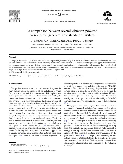
Abstract This paper presents a comparison between four vibration-powered generators designed to power standalone systems, such as wireless transducers. Ambient vibrations are converted into electrical energy using piezoelectric materials. The originality of the proposed approaches is based on a particular processing of the voltage delivered by the piezoelectric material, which enhances the electromechanical conversion. The principle of each processing circuit is detailed. Experimental results confirm the predictions given by an electromechanical model: compared to usual generators, the proposed approaches dramatically increase the power of the generators. © 2005 Elsevier B.V. All rights reserved.
Sensors and Actuators A 126 (2006) 405–416
A comparison between several vibration-powered piezoelectric generators for standalone systems
- 1、下载文档前请自行甄别文档内容的完整性,平台不提供额外的编辑、内容补充、找答案等附加服务。
- 2、"仅部分预览"的文档,不可在线预览部分如存在完整性等问题,可反馈申请退款(可完整预览的文档不适用该条件!)。
- 3、如文档侵犯您的权益,请联系客服反馈,我们会尽快为您处理(人工客服工作时间:9:00-18:30)。
Available online at Comparison of different DC voltage supervision strategies in a local Power Distribution System of More Electric AircraftHe Zhang a,∗,Christophe Saudemont a,Benoît Robyns a,Régis Meuret ba Ecole des Hautes Etudes d’Ingénieur(HEI),Laboratory of Electrotechnics and Power Electronics of Lille(L2EP),13,rue de Toul,59046Lille,Franceb Hispano-Suiza Group SAFRAN,Moissy Cramayel,FranceReceived1October2008;received in revised form29April2010;accepted10May2010Available online16May2010AbstractThe local DC Power Distribution System of More Electric Aircraft is one of the cores of the electric power transmission.Because of some unidirectional devices(diode bridge and anti-run-back diodes),the system is not totally reversible.Some storage and dissipation systems are necessary to store or/and dissipate the returned energy to maintain the DC bus voltage and to increase the energy efficiency.This paper introduces four supervision strategies in two levels to maintain the DC bus voltage and compares these strategies with the help of two criteria:the voltage performance and efficiency.©2010IMACS.Published by Elsevier B.V.All rights reserved.Keywords:On-board network;Fuzzy logic supervision;DC power supply;Power distribution1.IntroductionThe More Electric Aircraft(MEA)is the trend of the future aircraft because of ecological,economic and sustainable development reasons.The replacement of the mechanical,hydraulic and pneumatic power transfers by an electrical one is one of the most important innovations[5,9]of MEA.In the European Power Optimized Aircraft project(POA),it has been proven that the use of a local DC Power Distribution System(PDS)makes it possible to reach the subsystems optimum in order to get some benefits,like a weight reduction for example.Such a PDS is a local sub-network supplying loads such as,for example,flight control loads,landing system,etc.There are a lot of storage system applications in hybrid electric vehicles[7],power distribution systems[8]and wind powerfields[1,6].Because of the bidirectional characteristics of the loads and unidirectional characteristic of source and different dynamic characteristic between the two,the consumed power and supplied power will be unbalanced in some cases.It will consequently cause some instability of voltage and frequency.The main function of the storage system in these applications is to ensure the power balance between the loads and the supplier.It takes the role of load or supplier according to the case in order to control the voltage[1,7,8]and/or frequency[2],also to have some economic effects[6].Some control and supervision strategies,with the help of fuzzy logic or PI controller,are developed to control the DC bus voltage and improve the performance of power systems in these applications.But the dynamic∗Corresponding author.E-mail address:he.zhang@hei.fr(H.Zhang).0378-4754/$36.00©2010IMACS.Published by Elsevier B.V.All rights reserved.doi:10.1016/j.matcom.2010.05.009264H.Zhang et al./Mathematics and Computers in Simulation81(2010)263–276Fig.1.Definition of local DC power distribution system.( P/ t)of the load profile in the aeronautic domain is faster than in thesefields(hybrid electric vehicle,power distribution system and wind power)[10].In this context,a hybrid storage and dissipation system is proposed for the reason of dynamic compensation and security.In order to achieve the aim of voltage control and,at the same time, energetic optimization in the fast dynamic application,the network supervision becomes a synthesis problem.This paper presents some control strategies for this hybrid storage and dissipation system to ensure that the DC bus voltage is in the range of acceptable tolerance and to optimize the energy efficiency.In Section2,a local DC PDS of MEA is defined.The different supervision strategies with the help of fuzzy logic or PI controller are proposed in Section 3.In Section4,these strategies are tested in different conditions with the help of simulation.Two criteria(efficiency and voltage performance)are proposed to compare the simulation results.The conclusion is given in Section5.2.The definition of a local PDS and the problem facingThe DC local power distribution network under study is defined in Fig.1.This network includes2independent sources and3loads in which2are bidirectional.Among both sources(PMG or AC aircraft network),just one of them can be connected to the DC network at the same time.The rated voltage of DC bus is270V,but the permissible tolerance is between250V and280V as shown in Fig.2according to the standard MIL-STD-704[3].Because of some unidirectional devices(diode bridge and anti-run back diodes),the electrical energy cannot return to the source Permanent Magnet Generator(PMG)or AC aircraft network.When the sum of returned power of load1and load2is greater than the consumed power of load3,the diodes are turned off and the returned energy is stored in the capacitors. This will cause an over-voltage of DC bus.A hybrid storage and dissipation system(shown in Fig.3)can be used to resolve this problem.A resistance associated with a chopper can compensate the dynamic weakness of the storage system.Also,it can be the backup of the storage system when the storage system is disabled.3.Supervision strategiesTo control this hybrid system,two levels of supervision strategies have to be considered individually.First level,to determine the total absorbed or generated power reference of the hybrid system,P total.Second level,to split the P total into two parts:the part to store,P stor and the part to dissipate,P resi.For each supervision level,different strategies are proposed.Fig.4shows the global structure of the different supervision strategies.The detail of each strategy will be presented in the following parts.Table1summarizes the objectives,constraints,means of action and tools used for each proposed strategy.3.1.Level I:determination of the total power referenceAs mentioned above,the aim of thefirst supervision level is to determine the total power reference in order to maintain the DC bus voltage.H.Zhang et al./Mathematics and Computers in Simulation81(2010)263–276265Fig.2.V oltage standard of MIL-STD-704.Fig.3.Hybrid storage and dissipation system.Fig.4.The global structure of two level supervision strategies.266H.Zhang et al./Mathematics and Computers in Simulation81(2010)263–276Table1Objectives,constraints and action means of each power management strategy.Strategy Objectives Constraints Means of action ToolsLevel IPI DC bus standardTo maintain the DC bus voltage Storage limit P total PI controllerThe principle source is unidirectionalMP To maintain the DC bus voltage DC bus standard Fuzzy logic To maintain the PMG working Storage limit P totalTo manage the capacity limit of the storage The principle source is unidirectionalLevel IIVB To maximize the utilization of storage DC bus standard P stor Fuzzy logicStorage dynamic P resiFC To compensate the storage dynamic DC bus standard P stor Power balanceStorage dynamic P resi3.1.1.Proportional Integral controller(PI)When the total load power is negative,the diodes are turned off and the voltage controller,Generator Control Unit (GCU),cannot control the bus voltage.From this moment,the hybrid system takes the role of the bus voltage controller. The bus voltage is measured to calculate how much power should be consumed in order to balance the exceeding power. In this case,a PI controller is used to calculate this reference power value P total.Fig.5shows an example of PI controller structure to control a system.The upper part represents the system to control.The typicalfirst order system is used where K sys represent the gain of the system andτsys represent the time constant of the system.The bottom part represents the PI controller.In our case,the system to control is shown in Fig.6.C equi represent the capacitor equivalent of these capacitors at the port of the loads and R c represent the equivalent leakage resistance of the capacitors.As shown in Fig.6and(1) and compared with Fig.5,we can choose the bus voltage V bus to be the variable to control.V bus I total =R cC equi·R c·s+1(1)Fig.5.Proportional Integral controller.Fig.6.The system to control.H.Zhang et al./Mathematics and Computers in Simulation81(2010)263–276267Fig.7.The strategy of Minimum supplied Power.3.1.2.Minimum supplied Power(MP)In the previous control strategy,when the recovered power is greater than the consumed power,the power supplied by the generator becomes null because the anti-run back diodes are turned off.In the Minimum supplied Power strategy, the hybrid storage system is controlled to be a power consumer when the loads return power.If the current is always nonzero,the GCU will always take in charge the voltage control.The description of the main function of this strategy is shown in Fig.7.This strategy has three goals.Firstly,this strategy should slow the tendency of the supplied power decreasing in order to avoid turning off the diodes.Secondly,sometimes,the dynamic of load is faster than the storage system.The storage system cannot achieve the reference power instantly.In this case,the current of the generator will be zero and the GCU will not take in charge the voltage control.The second goal is to control the bus voltage by using the storage system when the diodes are turned off.The third goal is to manage the storage system to ensure that it is always available to absorb and supply the energy.According to the goals mentioned above,the informations of the generator current I gen,the bus voltage V bus and the storage level store level are the inputs of this strategy and the total power reference P total(the output variable)will be sent to the hybrid storage system.In Fig.4the block MP shows the structure of this strategy.The power convention is defined as follows:consumed power is positive;generated power is negative.So,in this strategy,the power supplied by the generator,the DC bus voltage and the storage level should be supervised.The supervisor must ensure to provide the power reference P total.Fuzzy logic is well adapted to develop a multi variable supervisor to achieve power management[1,4,6].Fig.8(a)–(c)shows the input membership functions.Fig.8(d)shows the output membership function.According to the goals mentioned above,the fuzzy rules can be described as follows:if the generator supplies a high power and the storage level is high,then the hybrid system supplies power;if the generator supplies a low power and the storage level is low,then hybrid system absorbs power,etc.Because there are three inputs and one output,a 2D table is not sufficient to represent the function of the four variables.So the rules are studied in two cases:I gen is nonzero and I gen is zero.Tables2and3show the fuzzy rules of the MP strategy.Figs.9–11show the evolution of P total vs.the storage level and generator current under different voltage inputs. We can note that when the generator current is close to zero,the total power reference depends on the bus voltage value.At this moment,the storage system acts as a voltage controller.When the current is out of the zero zone, there is no difference between different voltage levels,because in this moment,the GCU take the role of voltage controller.268H.Zhang et al./Mathematics and Computers in Simulation81(2010)263–276Fig.8.Membership functions of Minimum supplied Power strategy.(a)Input1I gen,(b)input2V bus,(c)input3store level,and(d)output P total.3.2.Level II:determination of the power reference partitionIn the level II,the strategy to split the P total is discussed.Obviously,we could use only the resistance to dissipate all returned energy from loads.But in the aspect of energetic optimization and temperature constraint,this could not be considered as a satisfactory solution.The objective of the power partition is to use the storage system as much as possible to maintain the bus voltage.3.2.1.Voltage Band(VB)The rated voltage of the bus is270V,but the permissible tolerance is between250V and280V as shown in Fig.2 according to the standard MIL-STD-704[3].The objective of this strategy is to use the resistance as little as possible.A fuzzy logic supervisor is used in this strategy to determine a partition coefficient k in order to create P stor and P resi reference as expressed in(2).The bus voltage and its evolution are considered as the inputs of the supervisor.Table2Fuzzy rules:total power reference P total when I gen is nonzero.stor level I genBig Medium SmallBig Negative Negative Zero Medium Negative Zero Positive Small Zero Positive PositiveH.Zhang et al./Mathematics and Computers in Simulation81(2010)263–276269 Table3Fuzzy rules:total power reference P total when I gen is zero.stor level V busBig Medium SmallBig Positive Zero Negative Medium Positive Zero ZeroSmall Positive Zero Zero Fig.12shows the membership functions.Fig.13shows the variation of the partition coefficient k vs.the bus voltage and V/ t.P resi=k×P total(2)P stor=(1−k)×P totalAccording to the objective mentioned above,the fuzzy rules are shown in Table4Fig.9.Generated surface of MP strategy for P total when V bus is200V.Fig.10.Generated surface of MP strategy for P total when V bus is270V.270H.Zhang et al./Mathematics and Computers in Simulation81(2010)263–276Fig.11.Generated surface of MP strategy for P total when V bus is300V.3.2.2.Full Compensation(FC)Because of the storage system dynamics,its output power,P stor out,cannot reach the power reference instantly.In this case,the dissipation system is used to dissipate the exceeding power P resi.This strategy is expressed in(3) P stor=P total(3)P resi=P total−P stor outFig.12.The membership functions of V oltage Band strategy.(a)Input1V bus,(b)input2 V bus/ t,and(c)output the partition coefficient.H.Zhang et al./Mathematics and Computers in Simulation81(2010)263–276271Fig.13.Generated surface for partition coefficient of strategy VB.Fig.14.simplified model of storage.4.Simulation results and comparison of the strategiesIn this section,the four different strategies are tested.And the results are compared according to two criteria:An efficiency criterion in order to express the performance of energetic optimization,and a voltage criterion in order to express the voltage control performance.4.1.Simulation resultsTwo supervisor levels,with respectively two variants lead to four different strategies.The abbreviations PI+VB, PI+FC,MP+VB and MP+FC are used to identify the different strategies.To test the strategies,a simplified model of the storage system is used[2],as shown in Fig.14where P max is the output power limit;τstor is the time constant of the storage system and W stor is the energy stored by storage system. The cumulated total profile of the three loads is shown in Fig.15.From0to0.1s,the loads start up.From0.1s to 0.15s,the load power is constant.From0.15s,the bidirectional loads begin to regenerate power and the unidirectional load continues to consume power.Figs.16and17show respectively for the MP+VB and PI+FC strategies evolution of the DC bus voltage and gener-ator current(Figs.16(a)and17(a)),the stored power and the power dissipated in the resistance(Figs.16(b)and17(b)), the stored energy and the energy dissipated in the resistance(Figs.16(c)and17(c)).Because the comparison focuses on the strategy of voltage supervision by using the hybrid storage system,an ideal DC source is used to replace the Table4Fuzzy rules:The partition coefficient k.V bus/ t V busBig Medium Small Negative Small Small Small Zero Big Small Small Positive Big Small Small272H.Zhang et al./Mathematics and Computers in Simulation81(2010)263–276Fig.15.Load profile.source PMG in Fig.1in order to simplify the study.Because the PI strategy does not take into account the storage level,the capacity limit of storage system W max is set to a value great enough and the initial value of storage level is set to medium,in order to eliminate the saturation effect of storage system.In Fig.16,we observe that as long as the generator current,I gen,is different from zero,the DC voltage V bus is strictly controlled by this source at270V.ButFig.16.Result of strategy MP+VB withτstor=0.05s and P max=20kW.(a)Bus voltage and current of generator,(b)power dissipated in the resistance and stored,and(c)energy dissipated in the resistance and stored.Fig.17.Result of strategy PI+FC withτstor=0.05s and P max=20kW.(a)Bus voltage and current of generator,(b)power dissipated in the resistance and stored,and(c)energy dissipated in the resistance and stored.when I gen is null,because of returned power,the hybrid system becomes in charge of controlling the DC bus voltage instead of the generator.Then,if the storage device can not balance exceeded power because of its dynamic weakness, the VB strategy permits V bus to increase,in the limit described in Fig.2.If the voltage is over this limit,the dissipation system takes part in to dissipate exceeded power.When the hybrid system absorbs more than the returned power,I gen is different from zero,and then the generator is in charge of controlling V bus again.So,the succession of these different configurations is the reason of the bus voltage oscillation between0.15s and0.18s in Fig.16.The length of this period depends on the dynamic of storage system.4.2.Definition of criteria4.2.1.EfficiencyWe define the efficiency by(4),with stored energy variations, W stor,supplied energy variations, W gen and returned loads energy variations, W return.efficiency(%)=W storW gen+ W return×100%(4)The loads begin to return power at0.15s and the criteria will be calculated from this moment.4.2.2.Voltage performanceThe area surrounded by the rated voltage270V and measured voltage is calculated in order to evaluate the voltage performance.The criteria is computed by(5)and described in Fig.18.According to a condition of a voltage value inFig.18.Definition of criterion voltage performance.the acceptable tolerance range,the less area is,the better performance is.A =|V measur −270|dt(5)Same as the efficiency performance,the voltage area will be calculated from 0.15s.4.3.Efficiency and voltage performance comparisonFour series of tests have been carried out by using different dynamic parameter (time constant τstor and maximum power P max )of the storage system.In this comparison,the capacity of storage system W max has not been taken into account.The test results according to both criteria are shown in Table 5.If we place the results in an area–efficiency space,we can get Fig.19.As shown in Fig.19,for each series,the better voltage performance we obtain,the less efficiency we get.We connect the average point of each series with the origin point.We can find that the slope of the line identifies the dynamic characteristic of each series.Gentler the slope is,faster the dynamic is.We find that between the two dynamic parameters of storage system (the maximum power and the time constant),the time constant is the more important factor of efficiency and voltage performance.Table 6compares the slopes of each dynamic series.Table 5Result of efficiency and voltage performance (area).Level IILevel I MP PI P maxτstor P maxτstor 0.5s 0.05s 0.5s 0.05s Area (V s)Efficiency Area (V s)Efficiency Area (V s)Efficiency Area (V s)Efficiency VB 20kW 0.99021.4%0.12793.3%20kW 0.54040.4%0.19891.3%5kW 1.06417.3%0.44379.1%5kW 0.62019.7%0.3079.3%FC20kW 0.00913.2%0.00966.5%20kW 0.15313.1%0.15266.1%5kW0.0099.2%0.00946.7%5kW0.15313.1%0.15266.1%Table 6The slope of different dynamic series.P maxτstor 0.5s0.05s 20kW 1.920.155kW3.120.34Fig.19.The comparison of different strategies on different condition.Table7Comparison of the strategies.Level II Level IMP PIAdvantage Drawback Advantage DrawbackVB Possible to supervise the storage level,high efficiency performance Complex implementation High efficiency performance Impossible to supervise thestorage levelFC The highest voltage performance Low efficiency performance Simple implementation,highvoltage performanceLow efficiency performanceIn another side,different strategies have different performance in the same dynamic series.Wefind that the VB strategy of level II can always obtain the best efficiency compared with FC strategy,because the strategy VB makes use of the voltage tolerance to utilize the storage as much as possible in order to increase the efficiency.For the level I,the choice of the strategy influences less the result of efficiency and voltage performance.The strategy MP has the capacity to control the storage level.But the strategy PI cannot take into account this aspect.Table7compares the advantage and drawback of the four strategies.5.ConclusionThe storage system can take the role of power supplier or load to keep the power balance in many applicationfields. Because of the fast dynamic of the load profile in aeronautic domain,the configuration of hybrid storage and dissipation system can be a new feasible solution.In order to maintain the DC bus voltage and,at the same time,consider the energy efficiency in the fast dynamic application,some supervision strategies are introduced in this paper.These strategies are separated into two independent levels.For each level,there are two different strategies.The strategies in different levels can be combined freely,therefore there are four supervision strategies.To compare the simulation results of the four supervision strategies,two criteria are introduced in this paper:the voltage and efficiency performance.The comparison shows that in this fast dynamic application,not only can the dynamic of the storage system affect the results,but also the supervision strategy can change the voltage-efficiency performance.Fuzzy logic was used in these strategies.It is well adapted to develop the multi objective supervision.The comparison shows the fuzzy logic supervision strategies have the better performance.AcknowledgmentsThis work was supported by afinancing from the regional Council Nord-Pas de Calais,HISPANO-SUIZA Company, and HEI.References[1]G.O.Cimuca,C.Saudemont,B.Robyns,M.M.Radulescu,Control and performance evaluation of aflywheel energy storage system associatedto a variable speed wind generator,IEEE Transactions on Industrial Electronics53(4)(2006)1074–1085.[2]V.Courtecuisse,M.El Mokadem,B.Robyns,B.Francois,M.Petit,J.Deuse,Association of wind turbine based dispersed generators andstorage systems to participate in primary frequency control,in:12th European Conference on Power Electronics and Applications,EPE, Aalborg,Denmark,2007.[3]Department of Defense of United States of America,Department of Defense Interface Standard–Aircraft Electric Power Characteristics,Military Standard of USA,2004.[4]L.Karunarathne,J.T.Economou,K.Knowles,Fuzzy logic control strategy for fuel cell/battery aerospace propulsion system,in:IEEE VehiclePower and Propulsion Conference(VPPC),Harbin,China,2008.[5]nglois,E.Foch,X.Roboam,H.Piquet,De l’avion plusélectriqueàl’avion toutélectrique:état de l’art et prospective sur les réseaux debord,J3EA,4(1)(2005),/more.php?rub=j3ea&vol=vol4HS1&cont=tdm.[6]L.Leclercq,B.Robyns,J.Grave,Control based on fuzzy logic of aflywheel energy storage system associated with wind and diesel generators,Mathematics and Computers in Simulation63(2003)271–280.[7]W.Lhomme,P.Delarue,A.Bouscayrol,P.Le Moigne,Control Strategies for Maximum Storage of Supercapacitor System,ESSCAP’06,Lausanne,Switzerland,2006,CD-ROM.[8]P.Thounthong,S.Raël,B.Davat,Control strategy of fuel cell and supercapacitors association for a distributed generation system,IEEETransactions on Industrial Electronics54(6)(2007)3225–3233.[9]D.Van Den Bossche,More electric control surface actuation,in:10th European Conference on Power Electronics and Applications,EPE,Toulouse,France,2003.[10]H.Zhang,C.Saudemont,B.Robyns,M.Petit,Electrical features comparison between more electric aircrafts and hybrid electric vehicles,Electromotion Journal16(2009)111–119.。