JBL 音箱说明书
JBL 音箱产品说明书
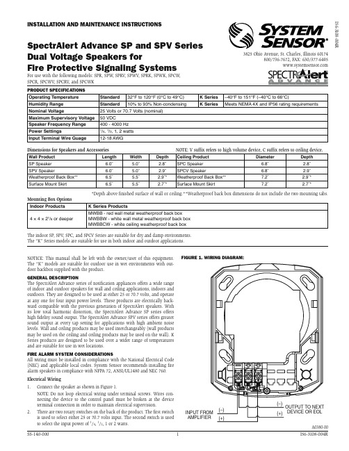
Figure 1. Wiring diagram:INPUT FROM AMPLIFIER OUTPUT TO NEXTDEVICE OR EOL(+)(–)(+)(–)A0380-00produCT SpeCiFiCaTionS Operating Temperature Standard 32°F to 120°F (0°C to 49°C)K Series –40°F to 151°F (–40°C to 66°C)Humidity Range Standard 10% to 93% Non-condensing K SeriesMeets NEMA 4X and IP56 rating requirementsNominal Voltage25 Volts or 70.7 Volts (nominal)Maximum Supervisory Voltage 50 VDCSpeaker Frequency Range 400 - 4000 Hz Power Settings1/4, 1/2, 1, 2 watts Input Terminal Wire Guage 12-18 AWGDimensions for Speakers and Accessories NOTE: V suffix refers to high volume device, C suffix refers to ceiling device.Wall Product Length Width Depth Ceiling ProductDiameter Depth SP Speaker 6.0˝ 5.0˝ 2.8˝SPC Speaker 6.8˝ 2.8˝SPV Speaker6.0˝ 5.0˝ 2.9˝SPCV Speaker6.8˝ 2.9˝Weatherproof Back Box** 6.5˝ 5.5˝ 2.9˝*Weatherproof Back Box**7.2˝ 2.9˝*Surface Mount Skirt 6.5˝5.5˝2.7˝*Surface Mount Skirt7.2˝2.7˝**Depth above finished surface of wall or ceiling.**Weatherproof back box dimensions do not include the two mounting tabs.Mounting Box Options Indoor Products K Series Products4 × 4 × 21/8 or deeperMWBB - red wall metal weatherproof back box MWBBW - white wall metal weatherproof back box MWBBCW - white ceiling weatherproof back boxThe indoor SP, SPV , SPC, and SPCV Series are suitable for dry and damp environments.The “K” Series models are suitable for use in both indoor and outdoor applications.NOTICE: This manual shall be left with the owner/user of this equipment. The “K” models are suitable for outdoor use in wet environments with out-door backbox supplied with the product.generaL deSCripTionThe SpectrAlert Advance series of notification appliances offers a wide range of indoor and outdoor speakers for wall and ceiling applications, indoors and outdoors. They are designed to be used at either 25 or 70.7 volts, and operate at any one for four input power levels. These products are electrically back-ward compatible with the previous generation of SpectrAlert speakers. With its low total harmonic distortion, the SpectrAlert Advance SP series offers high fidelity sound output. The SpectrAlert Advance SPV series offers greater sound output at every tap setting for applications with high ambient noise levels. Wall and ceiling products may be used interchangeably (wall products may be used on the ceiling and ceiling products may be used on the wall). K Series products are designed to be used over a wider range of temperatures and are suitable for use in wet locations.Fire aLarm SYSTem ConSideraTionSAll wiring must be installed in compliance with the National Electrical Code (NEC) and applicable local codes. System Sensor recommends installing fire alarm speakers in compliance with NFPA 72, ANSI/UL1480 and NEC 760.Electrical Wiring 1. Connect the speaker as shown in Figure 1.N OTE: Do not loop electrical wiring under terminal screws. Wires con-necting the device to the control panel must be broken at the device terminal connection in order to maintain electrical supervision.2.T here are two rotary switches on the back of the product. The first switch is used to select either 25 or 70.7 volts input. The second switch is used to select the input power of 1/4, 1/2, 1 or 2 watts.3825 Ohio Avenue, St. Charles, Illinois 60174800/736-7672, FAX: 630/377-6495inSTaLLaTion and mainTenanCe inSTruCTionSSpectralert advance Sp and SpV Series dual Voltage Speakers forI56-3108-004RFigure 2.Speaker WaTTage and VoLTage SeTTingS:A0419-00 ShorTing SpringNOTE: A shorting spring is provided between terminals 2 and 3 of the mount-ing plate to enable wiring checks after the system has been wired, but prior to installation of the final product. This spring will automatically disengage when the product is installed, to enable supervision of the final system. Figure 3:A0381-00TabLe 1. Sound LeVeLS For eaCh TranSFormer poWer Tap: UL Reverberant (dBA @ 10 ft.)SP, SPC SPV, SPCV2W86901W83871/2W80841/4W7781 NOTE: V suffix refers to high volume device,C suffix refers to ceiling mount device.Consequently, an incorrect tap connection may cause speaker damage. This means that if a 25V tap is selected when a 70.7V amplifier is being used, speaker damage may result. Therefore, be sure to select the proper taps for the amplifier voltage/input power level combination being used.mounTing indoor WaLL or CeiLing produCTS1. A ttach mounting plate to junction box as shown in Figures 4 and 5. Themounting plate is compatible with 4˝ x 4˝ x 21/8˝ junction boxes. If usinga back box skirt or trim ring, attach the mounting plate to the skirt ortrim ring and then attach the entire assembly to the junction box (see Figures 4, 5, 6 and 7).2. Connect field wiring to terminals, as shown in Figure 1.3. I f the product is not to be installed at this point, use the paint cover toprevent contamination of the mounting plate.4. T o attach product to mounting plate, remove the paint cover, then hooktabs on the product housing into the grooves on the mounting plate.5. T hen, swing product into position to engage the pins on the product withthe terminals on the mounting plate. Make sure that the tabs on the back of the product housing fully engage with the mounting plate.6.S ecure product by tightening the single mounting screw in the front of the product housing. For tamper resistance, the standard captivated mounting screw may be replaced with the enclosed T orx screw.k SerieS mounTing1. K Series products may be used indoors or outdoors. They must be in-stalled using the proper SpectrAlert Advance weatherproof back box. Do not attempt to use boxes other than those specified for use with the product.2. T he plastic weatherproof back box is equipped with removable sideflanges for mounting. The back box may be secured directly to the wall or ceiling using the flanges(plastic or metal back boxes) or by using the knockout plugs(plastic back boxes). Knockout plugs are provided to mount directly to the wall or ceiling or to a 1900 weatherproof electrical box, see Figure 12.3. T hreaded holes are provided in the sides of the box for ¾ inch conduitadapters. Knockout plugs in the back of the box can be used for ½ or ¾ inch rear entry. Unused holes must be sealed. Plugs and O-Rings are provided with the box for this purpose.4. I t is the responsibility of the installer to make sure that all openings andconnections are sealed properly. Outdoor installations that are protected from direct exposure to rain are still subject to condensation or leakage through hidden areas, such as a soffit.5. W ater may pool on the back box due to condensation or direct exposureto rain or snow. Use watertight fittings for all wiring connections, includ-ing the knockout plugs on the back of the box. When using the plastic plugs to fill unused threaded holes, make sure the O-rings supplied are properly positioned on the plug. The plugs must be sealed with PTFE thread seal tape.UL ANechoic (dBA @ 10 ft.)SP, SPC SPV, SPCV2W88931W86901/2W83871/4W80846. A ttach the mounting plate to the weatherproof back box using the fournon-painted screws.7. F ollow steps 2-5 of the indoor mounting instructions to wire and attachthe product. The product must be mounted to the weather proof back box using the painted screws (wall product has 4 screws, ceiling product has 3 screws)The ‘hold-in-place’ snaps are not intended to secure the product to the back box. The product must be secured to the back box using the screws providedFigure 4. WaLL mounT produCT WiTh Trim ring:A0382-00Figure 5. CeiLing mounT produCT WiTh Trim ring:A0383-00Figure 6. WaLL mounT produCT WiTh baCk box SkirT:A0386-00Figure 7. CeiLing mounT produCT WiTh baCk box SkirT:A0385-00Figure 8. ouTdoor WaLL mounT produCT WiTh pLaSTiCWeaTherprooF baCk box:A0384-00 Figure 9. ouTdoor CeiLing mounT produCT WiTh pLaSTiCWeaTherprooF baCk box:A0420-00 Figure 10. ouTdoor WaLL mounT produCT WiTh meTaL WeaTherprooF baCk box:A0410-00 Figure 11. ouTdoor CeiLing mounT produCT WiTh meTaLWeaTherprooF baCk box:A0407-00A0424-00 Figure 12. For knoCkouTS uSe a FLaT bLade SCreWdriVer.NOTE: Place the blade alongthe edge of the slot and slowlywork your way around the slotas you strike the srewdriver.Three-Year LimiTed WarranTYSystem Sensor warrants its enclosed product to be free from defects in materials and workmanship under normal use and service for a period of three years from date of manufacture. System Sensor makes no other express warranty for this product. No agent, representative, dealer, or employee of the Company has the authority to increase or alter the obligations or limitations of this Warranty. The Company’s obligation of this Warranty shall be limited to the repair or replacement of any part of the product which is found to be defective in materials or workmanship under normal use and service during the three year period commencing with the date of manufacture. After phoning System Sensor’s toll free number 800-SENSOR2 (736-7672) for a Return Authorization number, send defective units postage prepaid to: System Sensor, Returns Department, RA#__________, 3825 Ohio Avenue, St. Charles, IL 60174. Please include a note describing the malfunction and suspected cause of failure. The Company shall not be obligated to repair or replace units which are found to be defective because of damage, unreasonable use, modifications, or alterations occurring after the date of manufacture. In no case shall the Company be liable for any consequential or incidental damages for breach of this or any other Warranty, expressed or implied whatsoever, even if the loss or damage is caused by the Company’s negligence or fault. Some states do not allow the exclusion or limitation of incidental or consequential damages, so the above limitation or exclusion may not apply to you. This Warranty gives you specific legal rights, and you may also have other rights which vary from state to state.FCC STaTemenTSpectrAlert speakers have been tested and found to comply with the limits for a Class Bdigital device, pursuant to part 15 of the FCC Rules. These limits are designed to providereasonable protection against harmful interference when the equipment is operated in a commercial environment. This equipment generates, uses, and can radiate radio fre-quency energy and, if not installed and used in accordance with the instruction manual, may cause harmful interference to radio communications. Operation of this equipment in a residential area is likely to cause harmful interference in which case the user will berequired to correct the interference at his own expense.Please refer to insert for the Limitations of Fire Alarm SystemsAlways make sure that the individual speakers are tested after installation per NFPA regulations.The speaker may not be heard. The loudness of the speaker meets (or exceeds) the cur-rent Underwriters Laboratories’ standards. However, the speaker may not attract the attention of a sound sleeper or one who has recently used drugs or has been drinking alcoholic beverages. The speaker may not be heard if it is placed on a different floor from the person in hazard or if placed too far away to be heard over the ambient noise. Traffic, air conditioners, machinery, or music appliances may prevent even alert personsfrom hearing the alarm. The speaker may not be heard by persons who are hearing impaired.The LimiTaTionS oF SpeakerS。
jbl音响说明书
jbl音响说明书篇一:JBL闹钟使用说明JBL闹钟使用说明一、闹钟屏蔽背光调节方法A:背光长亮模式1、按下闹钟顶部按键2、选择DISPLAY选项3、选择BRIGHTNESS选择4、选择所需要的背光亮度或选择AUTOB:背光熄灭模式1、按下闹钟顶部按键2、选择DISPLAY选项3、选择BRIGHTNESS选择4、把背光亮度调整到OFF(选择此模式后需看时间只要按下SNOOZE键即可)二、菜单显示时间:1、长按SNOOZE键3-5秒2、选择菜单延迟时间3、按保存选项篇二:JBL 260卫星音箱操作指南JBL 260.5 200.5卫星音箱接线指南:1、JBL的每只卫星音箱都是直接接到功放,而不是先接到低音炮。
2、JBL卫星音箱除了中置音箱是横式的以外,2只主音箱和2只环绕音箱都是一样的,随便那2只作主音箱,那2只作环绕音箱都可以。
左音箱:FRONT L右音箱:FRONT R左环绕音箱:SURROUND L右环绕音箱:SURROUND R中置音箱:CENTER低音炮:SUBWOOFER 莲花口3、左环绕、右环绕音箱的确定:以人坐在沙发上,人的左手边的环绕就是左环绕音箱,人的右手边就是右环绕音箱。
4、低音炮接法:最上面的旋钮:SUBWOOFER LEVEL低音炮音量调节,一般可以打到一半,然后再根据每个客户的具体情况来调节大小。
中间有三个莲花输入口:1、LFE 紫色2、L 白色3、R 红色一般接LFE一个接口就可以了,L、R都不用接。
下面的音箱香蕉接线柱都不需要用,那是老式功放才要用的,现在的功放都不用了,现在的功放只需要输出已个低音炮音频信号给低音炮就可以了。
篇三:JBL扬声器※JBL扬声器扬声器是音响系统的喉舌,直接影响还音的音质,是音响系统最关健的部份。
它如像歌星的嗓子,有了好的歌喉,才能唱出优美动听的歌曲。
因此,如何选择好声音宏亮、音质优美、失真极微、工作可靠的扬声器是广大用户共同关心和追求的目标。
jbl音响使用说明

jbl音响说明书篇一:JBL闹钟使用说明JBL闹钟使用说明一、闹钟屏蔽背光调节方法A:背光长亮模式1、按下闹钟顶部按键2、选择DISPLAY选项3、选择BRIGHTNESS选择4、选择所需要的背光亮度或选择AUTOB:背光熄灭模式1、按下闹钟顶部按键2、选择DISPLAY选项3、选择BRIGHTNESS选择4、把背光亮度调整到OFF(选择此模式后需看时间只要按下SNOOZE键即可)二、菜单显示时间:1、长按SNOOZE键3-5秒2、选择菜单延迟时间3、按保存选项篇二:JBL 260卫星音箱操作指南JBL 260.5 200.5卫星音箱接线指南:1、JBL的每只卫星音箱都是直接接到功放,而不是先接到低音炮。
2、JBL卫星音箱除了中置音箱是横式的以外,2只主音箱和2只环绕音箱都是一样的,随便那2只作主音箱,那2只作环绕音箱都可以。
左音箱:FRONT L右音箱:FRONT R左环绕音箱:SURROUND L右环绕音箱:SURROUND R中置音箱:CENTER低音炮:SUBWOOFER 莲花口3、左环绕、右环绕音箱的确定:以人坐在沙发上,人的左手边的环绕就是左环绕音箱,人的右手边就是右环绕音箱。
4、低音炮接法:最上面的旋钮:SUBWOOFER LEVEL低音炮音量调节,一般可以打到一半,然后再根据每个客户的具体情况来调节大小。
中间有三个莲花输入口:1、LFE 紫色2、L 白色3、R 红色一般接LFE一个接口就可以了,L、R都不用接。
下面的音箱香蕉接线柱都不需要用,那是老式功放才要用的,现在的功放都不用了,现在的功放只需要输出已个低音炮音频信号给低音炮就可以了。
篇三:JBL扬声器※JBL扬声器扬声器是音响系统的喉舌,直接影响还音的音质,是音响系统最关健的部份。
它如像歌星的嗓子,有了好的歌喉,才能唱出优美动听的歌曲。
因此,如何选择好声音宏亮、音质优美、失真极微、工作可靠的扬声器是广大用户共同关心和追求的目标。
JBL 音箱说明书
Technical ManualJBL NORTHRIDGE E80Acoustic & Electrical specification:•Nominal Impedance: 8 ohm •Recommended amp power max: 200W•Frequency response: 38Hz -20KHz - 3dB •Sensitivity 91 dB at 2.8volt,1 metre • Crossoverfrequency 300Hz,4000Hz Physical Specifications:•Enclosure Dimension: H927mm, W: 213mm, D:349mm •Speaker Weight 19.1Kg each• Woofer: Dual 6” 170mm PolyPlas Shielded •Midrange: 4” 100mm PolyPlas shielded •Tweeter: ¾” 19mm titanium-laminate dome shielded •Terminal: gold plated, Bi wireableSpecificationCapacitors C1 102uF/100VC2 30uF/100VC3 50uF/100VC4 10uF/100VC5 5.1uF/100VResistor R1 10ohm/5WR2 1.5ohm/5WR3 1.5ohm/5WCoil L1 4.8mH/ø1.2mmL20.1mH/ø0.7mmL30.6mH/ø0.9mmL40.12mH/ø0.7mmWire IN1+ RedIN1- BlkIN2+ RedIN2- BlkW1+ GrnW1- Grn/BlkW2+ GrnW2- Grn/BlkM+ WhtM- Wht/blkT+ YelT- Yel/BlkHarman International SNC - Harman Consumer International 2, route de Tours 72500 Château du Loir 1Harman International SNC - Harman Consumer International 2, route de Tours 72500 Château du Loir 2Technical ManualJBL NORTHRIDGE E80Part listITEM Model/colorPart number Descriptionqty ITEM Model/color Partnumber Description qty 1 E80 BK/BE/CH 338035-001 ASY,TWTR,3/4 1 10 E80 BK/BE/CH 338037-001 FT,RUBBER-ASSY/THD IN 4 2 E80 BK/BE/CH 350354-001 GSKT,TWTR PL-NE SER 1 11 E80 BK/BE/CH 350542-001 ASY.LOGO-NE-SER 1 3 E80 BK/BE/CH 338059-001 BAR,HOLD DOWN-NRTHDGE 1 12 E80 BK 333249-001 CUP,GRL-HLS retainer 8 4 E80 BK/BE/CH 350130-001 PL,FACE,TWTR-NE SER 1 13 E80 BE/CH 333249-003 CUP,GRL-INTRMZO retainer 8E80BK/BE/CH 350124-001 ASY,GRL,FRNT,E80 SERI 1 5 E80 BK/BE/CH 335588-002 ASY,MIDRNG-N38II/ND31 1 15 E80 BK/BE/CH 350066-001 ASY,PTB-E80 Port tupe 1 6 E80BK/BE/CH 350144-001 RING,TRIM,4",MDRNG,E 117 E80BK/BE/CH 339097-001 CAUTION STICKER 1 7 E80 BK/BE/CH 350540-001 ASY,WFR,6"-NS-W6SH 2 18 E80 BK/BE/CH 350125-001 FOILCAL,E80 SERIES 1 E80 BK/BE/CH 350123-001 ASY,XOVER-E80 SERIES 1 19 E80 BK/BE/CH 350161-001 LBL,JBL"Assem. in Mex 1 9 E80 BK/BE/CH 351317-001 T-CUP,BI-WIRE,PLSTC-N 1 E80 BK/BE/CH 39106S NAIL,FNSHG,1" 4 E80BK/BE/CH 903401-012 SCR,PB,PPH,#6x.75,BLK 8 E80BK/BE/CH 903802-012 SCR,PB,HXS,#8x.75,ZIN 12 E80BK/BE/CH 905402-010 SCR,MS,PPH,H/L,6-19X5 2 E80BK/BE/CH 908302-012 SCR,PB,HXS,#6x.75,ZIN 81,2,3,4 5,67 712/13 1511 109191817。
jbl音响使用说明
jbl音响说明书篇一:JBL闹钟使用说明JBL闹钟使用说明一、闹钟屏蔽背光调节方法A:背光长亮模式1、按下闹钟顶部按键2、选择DISPLAY选项3、选择BRIGHTNESS选择4、选择所需要的背光亮度或选择AUTOB:背光熄灭模式1、按下闹钟顶部按键2、选择DISPLAY选项3、选择BRIGHTNESS选择4、把背光亮度调整到OFF(选择此模式后需看时间只要按下SNOOZE键即可)二、菜单显示时间:1、长按SNOOZE键3-5秒2、选择菜单延迟时间3、按保存选项篇二:JBL 260卫星音箱操作指南JBL 260.5 200.5卫星音箱接线指南:1、JBL的每只卫星音箱都是直接接到功放,而不是先接到低音炮。
2、JBL卫星音箱除了中置音箱是横式的以外,2只主音箱和2只环绕音箱都是一样的,随便那2只作主音箱,那2只作环绕音箱都可以。
左音箱:FRONT L右音箱:FRONT R左环绕音箱:SURROUND L右环绕音箱:SURROUND R中置音箱:CENTER低音炮:SUBWOOFER 莲花口3、左环绕、右环绕音箱的确定:以人坐在沙发上,人的左手边的环绕就是左环绕音箱,人的右手边就是右环绕音箱。
4、低音炮接法:最上面的旋钮:SUBWOOFER LEVEL低音炮音量调节,一般可以打到一半,然后再根据每个客户的具体情况来调节大小。
中间有三个莲花输入口:1、LFE 紫色2、L 白色3、R 红色一般接LFE一个接口就可以了,L、R都不用接。
下面的音箱香蕉接线柱都不需要用,那是老式功放才要用的,现在的功放都不用了,现在的功放只需要输出已个低音炮音频信号给低音炮就可以了。
篇三:JBL扬声器※JBL扬声器扬声器是音响系统的喉舌,直接影响还音的音质,是音响系统最关健的部份。
它如像歌星的嗓子,有了好的歌喉,才能唱出优美动听的歌曲。
因此,如何选择好声音宏亮、音质优美、失真极微、工作可靠的扬声器是广大用户共同关心和追求的目标。
JBL SW10 无线深音箱说明书

Impact puissant sans les filsLe caisson de graves actif sans fil JBL SW10 ajoute des graves profonds et percutants à la JBL LINK BAR, pour créer l’expérience sonore immersive ultime. Équipé d’un haut-parleur grave de 10" orienté vers le bas, d’un caisson bass reflex et d’un amplificateur de 300 watts accordés, le JBL SW10 produit des graves riches et saisissants sans la contrainte des câbles. Afin d’offrir des options de positionnement flexibles, JBL a intégré une architecture de conception à projection vers le bas afin de rendre l’emplacement dans la pièce beaucoup moins sensible. Le SW10 est le complément idéal quand vous recherchez les vrais graves profonds de JBL.CaractéristiquesH aut-parleur de graves 10 pouces (250 mm)Connexion audio sans fil Design port bass-reflex Configuration facileHARMAN International Industries, Incorporated 8500 Balboa Boulevard, Northridge, CA 91329 USA © 2019 HARMAN International Industries, Incorporated. Tous droits réservés. JBL est une marque commerciale de HARMAN International Industries, Incorporated, déposée aux États-Unis et/ou dans d’autres pays. Les caractéristiques, les spécifications et l’aspect sont susceptibles d’être modifiés sans préavis.Spécifications techniques :P uissance maximale : 300 WC onsommation de courant (en veille) :< 0.5 WD imensions du haut-parleur de graves :1 x 10" (250mm)Réponse en fréquence : 35 Hz à 120 HzT empérature de fonctionnement :0 °C à 45 °CM odulation de l’émetteur radio 5,8G :GFSKP lage de fréquences radio 5,8G:5740 MHz – 5840 MHzP uissance max. de l’émetteur 5,8G :8 dBmD imensions (L x H x P) :12" x 16" x 12" (305 x 440 x 305 mm)P oids : 27,2 lb (12,3 kg)D imensions de l’emballage (L x H x P) :14" x 20" x 14" (360mm x 503mm x360mm)P oids de l’emballage (brut) :29,8 lb (13,5 kg)C ompatibilité du JBL SW10 :JBL LINK BAR。
JBL ES系列音箱用户指南说明书

E n g l i s hES150PW, ES250PW (230V)ES SERIESOWNER’S GUIDE®1.Read these instructions.2.Keep these instructions.3.Heed all warnings.4.Follow all instructions.5.Do not use this apparatus near water.6.Clean only with a dry cloth.7.Do not block any ventilation openings. Install in accordance with the manufacturer’s instructions.8.Do not install near any heat sources such as radiators, heatr egisters, stoves or other apparatus (including amplifiers) thatp roduce heat.9.Do not defeat the safety purpose of the polarized or g rounding-type plug. A polarized plug has two blades with one wider than the other. A grounding-type plug has two blades and a third grounding prong. The wide blade or the third prong is provided for your safety.If the provided plug does not fit into your outlet, consult ane lectrician for replacement of the obsolete outlet.10.Protect the power cord from being walked on or pinched, particularly at plugs, convenience receptacles and the point where they exit from the apparatus.11.Only use attachments/accessories specified by the manufacturer.e only with the cart, stand, tripod, bracket ortable specified by the manufacturer or sold with thea pparatus. When a cart is used, use caution whenmfrom tip-over.13.Unplug this apparatus during lightning storms or when unused for long periods of time.14.Refer all servicing to qualified service personnel. Servicing is required when the apparatus has been damaged in any way, such as power supply cord or plug is damaged, liquid has been spilled or objects have fallen into the apparatus, or the apparatus has been exposed to rain or moisture, does not operate normally or has been dropped.15.Do not expose this apparatus to dripping or splashing and ensure that no objects filled with liquids, such as vases, are placed on the apparatus.16.To completely disconnect this apparatus from the AC Mains,d isconnect the power supply cord plug from the AC receptacle.17.The mains plug of the power supply cord shall remain readily operable.18.Do not expose batteries to excessive heat such as sunshine, fire or the like.oltage” within the product’s enclosure that maye lectric shock to persons.this apparatus to rain or moisture.IMPORTANT SAFETY INSTRUCTIONS2INTRODUCTIONJBL®ES150PW/ES250PWWireless Powered SubwoofersFor more than 60 years, JBL audio equipment has been used in con-cert halls, recording studios and movie theaters around the world, and has become the hands-down choice of leading recording artists and sound engineers.With the JBL ES Series, innovative technologies such as titanium-laminate-dome tweeters, Elliptical Oblate Spheroidal™(EOS) wave-guides and PolyPlas™transducer reinforcement are available to you. Enjoy!In addition, the ES150PW/ES250PW’s compact enclosure and wire-less capability allow for easy integration into any residential environ-ment. Enjoy!Unpacking the SubwooferIf you suspect damage from transit, report it immediately to your dealer. Keep the shipping carton and packing materials for future use.Included1 x Owner’s manual1 x Subwoofer1 x 230V AC cord for subwoofer – SCHUKO plug1 x 230V AC cord for subwoofer – UK plug1 x 5m Audio cable, RCA-RCA1 x Transmitter module1 x Power supply for transmitter1 x 230V AC power cord for transmitter power supply –SCHUKO plug1 x 230V AC power cord for transmitter power supply – UK plug1 x 2m Audio cable, RCA-RCA1 x Wall-mount bracket for transmitter (with two pan-head M3 x4 machine screws for attaching wall-mount bracket to trans-mitter)4 x Small, round, self-adhesive feet – to be attached on trans-mitter’s left side panel if transmitter is to be used vertically PLACEMENTSince the installation of a subwoofer can be somewhat morec omplicated than installation of full-range speakers, it is essential that you read this section very carefully prior to connecting thes ubwoofer to your system.Should you have questions relating to your installation, it is advisable to contact either your dealer or the JBL Customer Service Department for advice.The ES150PW/ES250PW’s wireless capability makes it even easier to properly locate the subwoofer in your room. The performance of the subwoofer is directly related to its p lacement in the listening room and how you align the subwoofer with its satellite speakers. Setting the volume of the subwoofer in relationship to the left and right speakers is also of critical i mportance because it is essential that the subwoofer integrate smoothly with the entire system. Setting the subwoofer’s volume level too high will result in overpowering, boomy bass. Setting the volume level too low will negate the benefits of the subwoofer.Here are several additional facts on installation that may proveu seful. It is generally believed by most audio authorities that lowf requencies (below 125Hz) are nondirectional and, therefore,p lacement of a subwoofer within any listening room is not critical. While in theory it is true that the larger wavelengths of extremely low frequencies are basically nondirectional, the fact is that, when installing a subwoofer within the limited confines of a room,r eflections, standing waves and absorptions generated within the room will strongly influence the performance of any subwoofers ystem. As a result, specific location of the subwoofer becomes important, and we strongly recommend that you experiment with placement before choosing a final location.Placement will depend upon your room and the amount and quality of bass required (for example, whether or not your room permits placement of the subwoofer near either satellite).right-channel satellite speaker to re-create the actual location of bass instruments in an orchestra and/or add impact to movie sound-tracks.34Rear PanelCONTROLS AND CONNECTIONSChoose either Wireless or Wired connection, then follow the appro-priate instructions.WIRELESSConnecting the Subwoofer for Wireless Applicationsyour receiver to the Sub C on the transmitter.2.Plug the transmitter module’s power supply into the wall outlet,and connect the included power cord to the transmitter A . Make sure the Transmitter Antenna 9is extended upward.3.Set the ID code on the transmitter and subwoofer (B and 4) to the same position, as described on page 6. When connected prop-erly, the LED on the top of the subwoofer will be orange.4.Set the Low-Pass Selector 3to the “Off” position.NOTE:Some receivers have two subwoofer outputs. In that case,use either connector.WIREDConnecting the Subwoofer for Wired Applications If you have a Dolby ®Digital or DTS ®receiver/processor with a low-frequency-effects (LFE) or subwoofer output:If your receiver/processor does not contain a Dolby Digital or DTS processor, but has subwoofer outputs:either the L or R input.SYSTEM CONNECTIONS5OPERATIONPower OnConnect your signal source (such as an A/V receiver or preamplifier)to the transmitter (if using a wireless connection) or to the sub-woofer (if using a wired connection). Two single-RCA cords are pro-vided. While you would ordinarily use the short cable to connect tothe transmitter or the long one to connect to the subwoofer, eithercable can be used, depending on proximity to the signal source.There is no need or benefit gained from connecting the same sourceto both the transmitter and the subwoofer. However, you could con-nect two separate sources to the subwoofer by utilizing both itswired and wireless connections. Both signals will essentially bemixed and outputted by the subwoofer. Plug your transmitter’s (ifusing a wireless connection) and subwoofer’s AC cord into a walloutlet. Do not use the o utlets on the back of the receiver for the sub-woofer.Initially set the Subwoofer-Level Control 6to the “min” position. Turn on your sub by pressing the Power Switch 0on the rear panel. Turn on your entire audio system and start a CD or movie soundtrackat a moderate level.Auto On/StandbyTransmitter (Wireless Connection Only): The Status LED (not shown) will be lit in red when the unit is in Standby. When the trans-mitter receives an audio signal from the source, it will immediatelyturn on and the LED will turn to blinking green or solid green:RED = STANDBY (No signal detected, transmitter off)GREEN (BLINKING) = Transmitter is on but has not established a linkwith the wireless subGREEN (SOLID) = Transmitter is on and has already established a linkwith the wireless subThe transmitter will automatically enter Standby mode after approxi-mately 10 minutes when no signal is detected from your system. Subwoofer: With the Power Switch 0in the ON position, the Status LED on the top will remain lit to indicate the On/Standby mode of thesubwoofer.RED = STANDBY (No signal detected, Amp Off)GREEN = SUB ON (Wired signal detected, Amp On)ORANGE = SUB ON (Wireless link with transmitter active)The subwoofer will automatically enter the Standby mode afterapproximately 10 minutes when no signal is detected from yours ystem. The subwoofer will then power ON instantly when a signal isdetected. During periods of normal use, the Power Switch 0can be left on. You may turn off the Power Switch 0for extended periods of nonoperation, e.g., when you are away on vacation.Getting StartedConfirm that the Status LED on the transmitter is on (red or green), the Status LED on the subwoofer is on (red, orange or green) and an RCA cable is connected from a source unit to either the LFE Input of the subwoofer 2or transmitter C or L and R inputs 1on the sub-woofer. Play a CD or video. Use a selection that has ample bass information. If using a wireless connection, the Status LED on the transmitter should be lit in solid green, and the Status LED on the subwoofer should turn orange if connected wirelessly. If the LED on the transmitter is blinking in green and the LED on the subwoofer is in red or green, a wireless link has not been established between the transmitter and the subwoofer. If connecting directly to the sub-woofer without using the wireless link, the Status LED on the sub-woofer should be lit green. If the LED on the subwoofer remains red, check that the RCA cable from the source to subwoofer (wired con-nection) or transmitter (wireless connection) is functioning properly and that it is fully inserted at both ends, or that the Transmitter ID-Code Selector B and the Subwoofer ID-Code Selector 4are set to the same channel. Once you have a green or orange LED on the sub-woofer, turn your Subwoofer-Level Control 6up halfway so that the knob indicator points up. You should now be hearing bass informa-tion coming from the subwoofer.Adjust LevelSet the overall volume control of the preamplifier or stereo to ac omfortable level. Adjust the Subwoofer-Level Control 6until you obtain a pleasing blend of bass. Bass response should not over -power the room but rather be adjusted so there is a harmonious blend across the entire musical range. Many users have a tendency to set the subwoofer volume too loud, adhering to the belief that a subwoofer is there to produce lots of bass. This is not entirely true.A subwoofer is there to enhance bass, extending the response of the entire system so the bass can be felt as well as heard. However, overall balance must be maintained or the music will not soundn atural. An experienced listener will set the volume of the subwoofer so its impact on bass response is always there but never obtrusive.Phase ControlThe Phase Switch 7determines whether the subwoofer speaker’s pistonlike action moves in and out with the main speakers, 0˚, or opposite the main speakers, 180˚. Proper phase adjustment depends on several variables such as room size, subwoofer placement and listener position. Adjust the phase switch to maximize bass output at the listening position.Crossover AdjustmentThe Crossover Adjustment Control 5determines the highestf requency at which the subwoofer reproduces sounds. If your main speakers can comfortably reproduce some low-frequency sounds, set this control to a lower frequency setting, between 50Hz and100Hz. This will concentrate the subwoofer’s efforts on the ultradeep bass sounds required by today’s films and music.If you are using smaller bookshelf speakers that do not extend to the lower bass frequencies, set the Crossover Adjustment control to a higher setting, between 120Hz and 150Hz.NOTE: This control will have no effect if the LFE Input 2is used (wired connection) or if the Low-Pass Selector 3is in the “OFF”position (wireless connection). If you have a Dolby Digital or DTS processor/receiver, the Low-Pass Frequency is set by the proces-sor/receiver. Consult your owner’s manual to learn how to view or change this setting.ID CodesIn the unlikely event that you experience interference when operat-ing the system, or if you have more than one set of subwoofer trans-mitters and receivers in operation, you may change the channel in which the system operates. On the transmitter module and the sub-woofer, there is a four-position ID-Code Selector (B and 4). Simply set the selectors to one of the other positions. The transmitter and subwoofer (B and 4) selectors must be set to the same position for the system to function correctly. You can also set up a maximum of two subwoofers to be receiving from the same transmitter by set-ting the channel selector on the transmitter and both of the sub-woofers to the same channel.A Word About Wireless ProductsThe JBL ES150PW and ES250PW wireless subwoofers utilize advanced wireless transceivers operating in the 2.4GHz frequency band. This is the same frequency band that is used for wireless home networks and high-quality cordless phones.It also allows for the transmission of high-performance, full-spectrum sound to remote locations, wirelessly.Like all wireless devices, the JBL wireless subwoofer’s operating range may vary, depending upon variables such as building con-67SPECIFICATIONSES150PWES250PWFrequency Response 27Hz – 150Hz 25Hz – 150Hz Amplifier RMS Power300 Watts 400 Watts Amplifier Peak Dynamic Power †500 Watts700 WattsCrossover Frequency50Hz – 150Hz; 24dB/octave 50Hz – 150Hz; 24dB/octave continuously ajustable continuously ajustablewhen activatedwhen activatedDriver250mm (10") PolyPlas ™300mm (12") PolyPlas™Operating Range Up to 22m (75'),Up to 22m (75'),depending upon conditions depending upon conditions RF Operating Frequency 2.4GHz2.4GHzSubwoofer Dimensions 457mm x 337mm x 409mm 502mm x 400mm x 454mm (H x W x D)(18" x 13-1/4" x 16-1/8")(19-3/4" x 15-3/4" x 17-7/8")Transmitter Dimensions 95mm x 124mm x 100mm 95mm x 124mm x 100mm (H x W x D)(3-3/4" x 4-7/8" x 3-15/16")(3-3/4" x 4-7/8" x 3-15/16")Subwoofer Weight 17.7kg (39 lb)19.5kg (43 lb)Transmitter Weight0.2kg (0.5 lb)0.2kg (0.5 lb)†The Peak Dynamic Power is measured by recording the highest center-to-peak voltage m easured across the output of a resistive load equal to minimum impedance of the transducer, using a 50Hz sine wave burst, 3 cycles on, 17 cycles off.Laurent RaultHarman Consumer Group, Inc.Château du Loir, France 6/08Laurent RaultHarman Consumer Group, Inc.Château du Loir, France 6/08Features, specifications and appearance are subject to change without notice.JBL is a trademark of Harman International Industries, Incorporated, registeredin the United States and/or other countries. Elliptical Oblate Spheroidal, PolyPlas and Pro Sound Comes Home are trademarks of Harman International Industries, Incorporated. Dolby is a registered trademark of Dolby Laboratories.DTS is a registered trademark of DTS, Inc.。
- 1、下载文档前请自行甄别文档内容的完整性,平台不提供额外的编辑、内容补充、找答案等附加服务。
- 2、"仅部分预览"的文档,不可在线预览部分如存在完整性等问题,可反馈申请退款(可完整预览的文档不适用该条件!)。
- 3、如文档侵犯您的权益,请联系客服反馈,我们会尽快为您处理(人工客服工作时间:9:00-18:30)。
Technical Manual
JBL NORTHRIDGE E80
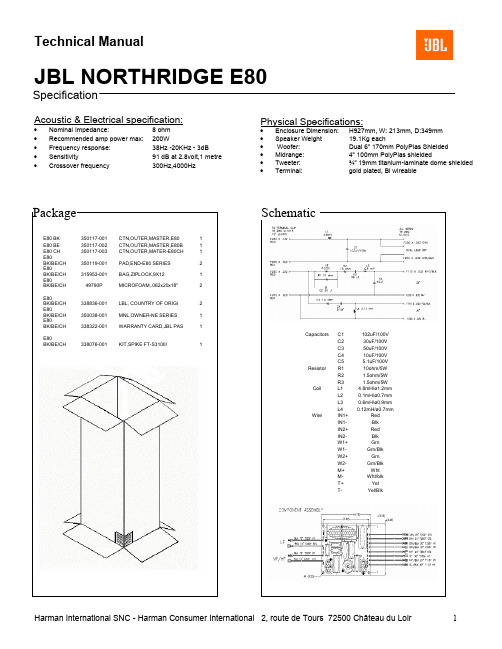
Acoustic & Electrical specification:
•Nominal Impedance: 8 ohm •Recommended amp power max: 200W
•Frequency response: 38Hz -20KHz - 3dB •Sensitivity 91 dB at 2.8volt,1 metre • Crossover
frequency 300Hz,4000Hz Physical Specifications:
•Enclosure Dimension: H927mm, W: 213mm, D:349mm •Speaker Weight 19.1Kg each
• Woofer: Dual 6” 170mm PolyPlas Shielded •Midrange: 4” 100mm PolyPlas shielded •Tweeter: ¾” 19mm titanium-laminate dome shielded •Terminal: gold plated, Bi wireable
Specification
Capacitors C1 102uF/100V
C2 30uF/100V
C3 50uF/100V
C4 10uF/100V
C5 5.1uF/100V
Resistor R1 10ohm/5W
R2 1.5ohm/5W
R3 1.5ohm/5W
Coil L1 4.8mH/ø1.2mm
L2
0.1mH/ø0.7mm
L3
0.6mH/ø0.9mm
L4
0.12mH/ø0.7mm
Wire IN1+ Red
IN1- Blk
IN2+ Red
IN2- Blk
W1+ Grn
W1- Grn/Blk
W2+ Grn
W2- Grn/Blk
M+ Wht
M- Wht/blk
T+ Yel
T- Yel/Blk
Harman International SNC - Harman Consumer International 2, route de Tours 72500 Château du Loir 1
Harman International SNC - Harman Consumer International 2, route de Tours 72500 Château du Loir 2
Technical Manual
JBL NORTHRIDGE E80
Part list
ITEM Model/color
Part number Description
qty ITEM Model/color Part
number Description qty 1 E80 BK/BE/CH 338035-001 ASY,TWTR,3/4 1 10 E80 BK/BE/CH 338037-001 FT,RUBBER-ASSY/THD IN 4 2 E80 BK/BE/CH 350354-001 GSKT,TWTR PL-NE SER 1 11 E80 BK/BE/CH 350542-001 ASY.LOGO-NE-SER 1 3 E80 BK/BE/CH 338059-001 BAR,HOLD DOWN-NRTHDGE 1 12 E80 BK 333249-001 CUP,GRL-HLS retainer 8 4 E80 BK/BE/CH 350130-001 PL,FACE,TWTR-NE SER 1 13 E80 BE/CH 333249-003 CUP,GRL-INTRMZO retainer 8
E80
BK/BE/CH 350124-001 ASY,GRL,FRNT,E80 SERI 1 5 E80 BK/BE/CH 335588-002 ASY,MIDRNG-N38II/ND31 1 15 E80 BK/BE/CH 350066-001 ASY,PTB-E80 Port tupe 1 6 E80
BK/BE/CH 350144-001 RING,TRIM,4",MDRNG,E 1
17 E80
BK/BE/CH 339097-001 CAUTION STICKER 1 7 E80 BK/BE/CH 350540-001 ASY,WFR,6"-NS-W6SH 2 18 E80 BK/BE/CH 350125-001 FOILCAL,E80 SERIES 1 E80 BK/BE/CH 350123-001 ASY,XOVER-E80 SERIES 1 19 E80 BK/BE/CH 350161-001 LBL,JBL"Assem. in Mex 1 9 E80 BK/BE/CH 351317-001 T-CUP,BI-WIRE,PLSTC-N 1 E80 BK/BE/CH 39106S NAIL,FNSHG,1" 4 E80
BK/BE/CH 903401-012 SCR,PB,PPH,#6x.75,BLK 8 E80
BK/BE/CH 903802-012 SCR,PB,HXS,#8x.75,ZIN 12 E80
BK/BE/CH 905402-010 SCR,MS,PPH,H/L,6-19X5 2 E80
BK/BE/CH 908302-012 SCR,PB,HXS,#6x.75,ZIN 8
1,2,3,4 5,6
7 7
12/13 15
11 10
9
19
18
17。