Users Guide XBee XBee-PRO Drop in Networking Accessories
Tobii PCEye Go 用户手册说明书

Tobii PCEye Go 用户手册用户手册Tobii PCEye Go版本2.808/2015版权所有。
Copyright©Tobii AB(publ)未经出版人事先书面许可,对本出版物的任何部分不得进行复制、保存于可检索系统内,也不得以任何形式或任何途径(如电子形式、复印、录制等)传播。
所主张的版权保护包括依成文法或司法规定而受版权保护的材料和信息的所有形式和事项,包括但不限于屏幕(如屏幕显示)、菜单等显示的软件程序生成的材料。
本文档中所含信息由Tobii Dynavox专有。
未经Tobii Dynavox事先书面授权,禁止复制任何部分或全部内容。
本文档内提及的产品是其相应所有者的商标和/或注册商标。
出版商和作者不对这些商标主张权利。
尽管在本文档的编写过程中采取了各种防范措施,但出版商和作者对本文档的任何错误或遗漏概不负责,对由于使用本文档所含信息或由于使用本文档随附的程序或源代码而引致的任何损失也概不负责。
无论在何种情况下,出版商和作者对本文档直接或间接导致的实际或指称的任何利润损失或其他商业损失一概无须负责。
内容若有更改,恕不另行通知。
请访问Tobii Dynavox网站查看本文档的更新版本。
以下产品受美国专利保护,专利号7,572,008:•Tobii PCEye Go您可以在背面的标签上找到Tobii PCEye Go产品的型号。
目录内容1简介 (6)1.1关于警示语的说明 (6)1.2符号与标志 (6)1.3预期用途 (6)1.4包装内容 (7)2安全性 (8)2.1安装警告 (8)2.2紧急警告 (8)2.3红外警告 (8)2.4癫痫警告 (8)2.5磁场警告 (8)2.6儿童安全 (8)2.7请勿拆开Tobii PCEye Go (9)2.8Gaze Interaction (9)3开始使用 (10)3.1Tobii PCEye Go安装指南 (10)3.2将Tobii PCEye Go装到您的显示器/笔记本电脑上 (10)3.3Tobii PCEye Go配置指南 (11)3.4软件更新 (13)4使用Tobii PCEye Go (14)4.1定位 (14)4.1.1跟踪箱 (14)4.1.2跟踪状态查看器 (15)4.1.2.1显示跟踪状态 (15)4.1.3定位指南 (15)4.2使用Windows Control (16)4.2.1Windows Control类型 (16)4.2.2启动和禁用Windows Control (17)4.2.3使用Gaze Selection (17)4.2.3.1Gaze Selection任务栏 (17)4.2.3.2任务按钮 (19)4.2.3.3Windows7里的功能重叠 (20)4.2.3.4Windows8里的功能重叠 (20)4.2.3.5Windows10里的功能重叠 (22)4.2.3.6在Windows8.1和Windows10中并排显示窗口/关闭应用 (24)4.2.3.6.1如何并排显示窗口/关闭应用 (24)4.2.3.6.2如何分屏并排更多应用 (26)4.2.3.7选择方法—Gaze(注视)和Switch(外置按钮) (28)4.2.3.7.1让外置按钮执行固定任务和默认左键单击/轻按 (28)4.2.3.7.2不用外置按钮而用键盘按键来激活任务 (28)4.2.3.8注视键盘 (29)4.2.3.8.1键盘任务栏 (30)4.2.3.8.2键盘任务栏的任务按钮 (31)4.2.3.8.3文字预测 (31)4.2.3.9结合基于区域键盘的Gaze Selection (32)4.2.4使用Mouse Emulation (32)4.2.4.1放置Mouse Emulation菜单 (32)4.2.4.2在Mouse Emulation模式下利用Windows Control进行点击 (32)4.2.4.3在Mouse Emulation模式下使用Windows Control进行放大 (33)4.2.4.4选择Mouse Emulation功能 (33)4.2.4.5在Mouse Emulation模式下暂停Windows Control (33)4.2.4.6在Mouse Emulation模式利用Windows Control进行滚动 (33)4.3暂停/继续Gaze Interaction (34)4.4Tobii PCEye Update Notifier (35)5Gaze Interaction设置 (36)5.1访问Gaze Interaction Settings (36)5.2校准 (37)5.2.1开始校准 (37)5.2.2中断校准 (37)5.2.3自定义活动眼 (38)5.2.4改进校准点 (39)5.2.5移除校准点 (40)5.2.6自定义校准 (40)5.2.7自定义校准区域 (41)5.3互动 (42)5.4用户配置文件 (43)5.4.1创建新的配置文件 (43)5.4.2选择当前的用户配置文件 (44)5.4.3删除配置文件 (44)5.5Windows Control (44)5.5.1自动启动 (44)5.5.2Windows Control类型 (44)5.5.2.1Gaze Selection (45)5.5.2.2Mouse Emulation (46)5.5.2.2.1鼠标控制速度 (46)5.5.2.2.2放大镜大小和缩放 (46)5.5.2.2.3自动从“鼠标右键单击”切换为“鼠标左键单击” (46)5.5.2.2.4关闭滚动功能 (46)5.5.2.2.5自定义光标 (46)5.5.2.2.6隐藏菜单 (47)5.6系统设置 (47)5.6.1系统屏幕外沿菜单 (47)5.6.2定位指南 (48)5.7系统信息 (49)5.7.1升级眼动仪固件 (49)6Gaze Selection设置 (50)6.1常规设置选项卡 (50)6.2键盘设置选项卡 (51)6.3任务栏设置选项卡 (52)6.3.1左键单击/轻敲最大化 (52)7产品保养 (53)7.1温度和湿度 (53)7.1.1一般用途 (53)7.1.2运输和储存 (53)7.2清洁 (53)7.3运送Tobii PCEye Go (53)7.4处置Tobii PCEye Go (53)附录A支持和保修 (54)附录B合规信息 (55)附录C第三方配件 (57)附录D技术规格 (58)1简介感谢您选购Tobii Technology公司的Tobii PCEye Go设备!为确保获得此产品的最佳性能,请仔细阅读本手册。
LTE-M Expansion Kit用户指南说明书
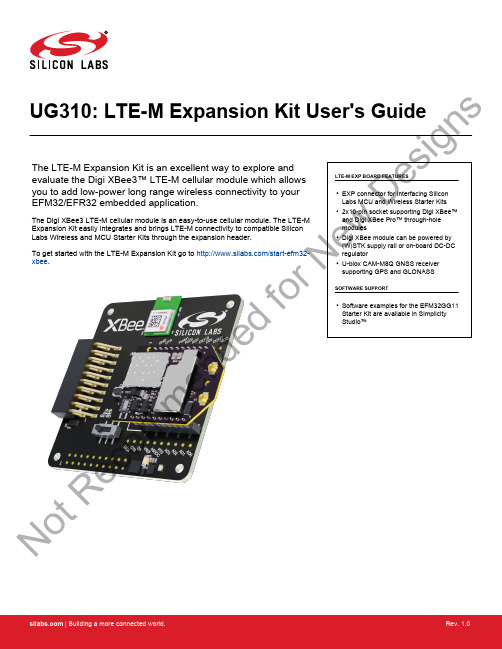
UG310: LTE-M Expansion Kit User's GuideThe LTE-M Expansion Kit is an excellent way to explore and evaluate the Digi XBee3™ LTE-M cellular module which allows you to add low-power long range wireless connectivity to your EFM32/EFR32 embedded application.The Digi XBee3 LTE-M cellular module is an easy-to-use cellular module. The LTE-M Expansion Kit easily integrates and brings LTE-M connectivity to compatible Silicon Labs Wireless and MCU Starter Kits through the expansion header.To get started with the LTE-M Expansion Kit go to /start-efm32-xbee .LTE-M EXP BOARD FEATURES•EXP connector for interfacing Silicon Labs MCU and Wireless Starter Kits •2x10-pin socket supporting Digi XBee™and Digi XBee Pro™ through-hole modules•Digi XBee module can be powered by (W)STK supply rail or on-board DC-DC regulator•U-blox CAM-M8Q GNSS receiver supporting GPS and GLONASSSOFTWARE SUPPORT•Software examples for the EFM32GG11Starter Kit are available in Simplicity Studio™No tR e co mme nd edf or N e wDe si g n sTable of Contents1. Introduction................................32. Hardware Overview .. (4)2.1 Hardware Layout . (4)3. Connectors (5)3.1 EXP Header...............................53.1.1 Pass-through EXP Header ........................63.1.2 EXP Header Pinout ...........................63.2 Digi XBee Module Socket ..........................73.2.1 Digi XBee Module Socket Pinout ......................83.2.2 Power Supply ....... (9)4. Using the LTE-M Expansion Kit (10)4.1 Board Identification............................104.2 Digi XBee3 LTE-M Module ..........................104.3 On-Board GNSS Receiver .................. (11)5. Schematics, Assembly Drawings, and BOM (13)6. Kit Revision History (14)6.1 SLEXP8021A Revision History ..................... (14)7. Document Revision History (15)No tR e co mme nd edf or N e wDe si g n s1. IntroductionThis user guide covers the usage of the Silicon Labs LTE-M EXP Board together with the Digi XBee3 LTE-M cellular module. The LTE-M EXP Board is designed to be compatible with all Digi XBee through-hole modules offering a wide array of wireless connectivity op-tions, such as Zigbee, Wi-Fi, 3G and LTE cellular to name a few.Software examples demonstrating how to use the LTE-M Expansion Kit with the EFM32GG11 Starter Kit are available through Simplici-ty Studio™.For more information about the Digi XBee modules see https:///xbee .IntroductionNo tR e co mme nd edf or N e wDe si g n s2. Hardware Overview2.1 Hardware LayoutThe layout of the LTE-M Expansion Kit is shown in the figure below.EXP-header for Starter KitsPower source select switchPass-through EXP-headerNot mountedDigi XBee Module ResetDigi XBee Module SocketDigi XBee Module Breakout HeaderNot mountedDigi XBee Module Breakout HeaderFigure 2.1. LTE-M Expansion Kit Hardware LayoutHardware OverviewNo tR e co mme nd edf or N e wDe si n s3. ConnectorsThis chapter gives an overview of the LTE-M Expansion Kit connectivity and power connections.EXP HeaderEXP Header (Not Mounted)(Not Mounted)(Not Mounted)Figure 3.1. LTE-M Expansion Kit Connector Layout3.1 EXP HeaderOn the left side of the LTE-M Expansion Kit, a right-angle female 20-pin EXP header is provided to allow connection to one of Silicon Labs’ MCU or Wireless Starter Kits. The EXP header on the Starter Kits follows a standard which ensures that commonly used periph-erals such as an SPI, a UART, and an I2C bus, are available on fixed locations on the connector. Additionally, the VMCU, 3V3 and 5V power rails are also available on the EXP header. For detailed information regarding the pinout to the EXP header on a specific Starter Kit, consult the accompanying kit user’s guide.The figure below shows how the Digi XBee module socket and the on-board GNSS receiver are connected to the EXP header and the peripheral functions that are available.VMCUXBEE_DINXBEE_DOUT XBEE_DIO4XBEE_RTS GNSS_RXD GNSS_TXD XBEE_PWM15V3V3GNDGNSS_TIMEPULSE XBEE_DTRGNSS_POWER_EN GNSS_VBCKP_EN XBEE_CTSXBEE_RSSI XBEE_ADC1BOARD_ID_SDA BOARD_ID_SCL Reserved (Board Identification)LTE-M EXP Board I/O PinFigure 3.2. EXP HeaderNo tR e co mme nd edf or De si g n s3.1.1 Pass-through EXP HeaderThe LTE-M Expansion Kit features a footprint for a secondary EXP header. All signals from the EXP header, including those that are not connected to any features on the LTE-M Expansion Kit are directly tied to the corresponding pins in the footprint, allowing daisy-chaining of additional EXP boards if a connector is soldered in.Pin 1 of the secondary EXP header is marked with a 1 in the silkscreen printing.3.1.2 EXP Header PinoutThe table below shows the pin assignments of the EXP header.Table 3.1. EXP Header PinoutNo tg n s3.2 Digi XBee Module SocketThe LTE-M Expansion Kit features two 1x10-pin 2mm pitch connectors for inserting a through-hole Digi XBee wireless module. There are also two unpopulated footprint for 1x10-pin 2.54mm (0.1") pitch pin headers which breaks out the signals of the Digi XBee module socket, an ASSOC status LED which indicates the wireless connection status of the Digi XBee module, and a reset button connected to the Digi XBee module's reset signal input.The pinout of the socket is illustrated in the figure below. The pinout of the unpopulated breakout headers are identical to the adjacent Digi XBee module socket connector.B E E _D I N X B E E _C T S B E E _D O U T X BE E _R T S N D B E E _V C CB E E _D I O 12X B E E _A DC 1X BE E _D I O 4B E E _P W M 1B E E _D T R B E E _R E S E T n B E E _R S S I X B E E _A D C 0X B E E _A D C 2X B E E _A D C 3X B E E _A S S O C X B E E _V R EF B E E _B KG O X B E E _O N Figure 3.3. Digi XBee Module SocketNo tR e co mme nd edf or e wDe si g n s3.2.1 Digi XBee Module Socket PinoutThe pin assignment of the Digi XBee module socket is given in the table below.Table 3.2. Digi XBee Module Socket Pin DescriptionsNo tR e co3.2.2 Power SupplyWhen connected to a Silicon Labs MCU or Wireless STK, the Digi XBee3 LTE-M cellular module can either be powered by the VMCU rail present on the EXP header, or through a DC-DC regulator onboard the LTE-M Expansion Kit. If connected to the VMCU rail of the starter kit, the current consumption of the Digi XBee3 LTE-M cellular module will be included in the starter kit's on-board Advanced Energy Monitor (AEM). The DC-DC regulator draws power from the 5V net, and hence, the power consumption of the Digi XBee3 LTE-M cellular module will not be included in any AEM measurements performed by the MCU STK.A mechanical power switch on the LTE-M Expansion Kit is used to select between Low Power (AEM) mode and High Power (DC-DC)mode. When the switch is set to Low Power (AEM) mode, the Digi XBee3 LTE-M cellular module is connected to the VMCU net on the EXP header. For most MCU Starter Kits, the regulator supplying the VMCU net is capable of sourcing up to 300 mA, bearing in mind that the MCU is also powered from this net. The EFM32GG11 starter kit and the Wireless Starter Kit main board are able to source up to 800 mA on the VMCU net (provided that the kit's power source is able to supply this much current). When the switch is set to High Power (DC-DC) mode, the Digi XBee3 LTE-M cellular module is connected to the output of the DC-DC converter, which is able to source up to 2 A (again, limited by the capability of the source powering the starter kit). For applications requiring higher power than what is available from the VMCU net, the power switch should be set to High Power (DC-DC) mode.The on-board GNSS receiver is powered from the same rail as the Digi XBee3 LTE-M cellular module through an analog switch that can be controlled by a GPIO pin on the EXP header.The power topology is illustrated in the figure below.Figure 3.4. LTE-M Expansion Kit Power TopologyNo tR e co mDe si g n s4. Using the LTE-M Expansion KitThe Digi XBee3 LTE-M cellular module is a wireless module providing cellular connectivity using the low-power LTE-M technology.4.1 Board IdentificationThe LTE-M EXP Board and the starter kit it is connected to are automatically identified by Simplicity Studio when connected to the computer to present the correct documentation and software examples. Note however that Simplicity studio is not able to identify which Digi XBee module is inserted into the LTE-M EXP Board's Digi XBee module socket.4.2 Digi XBee3 LTE-M ModuleThe Digi XBee3 LTE-M module requires an external antenna to enable wireless connectivity. Connect the included patch antenna to the module's u.FL connector labeled 'CELL' and insert the module into the socket as shown in the figure below, before connecting the board to a Silicon Labs MCU or Wireless starter kit.The kit also includes a SIM card, which needs to be activated before being inserted into the SIM slot of the Digi XBee3 LTE-M module.Refer to the LTE-M Expansion Kit Quick Start Guide for information on how to activate the SIM card.Figure 4.1. LTE-M Expansion Kit assembled for useUsing the LTE-M Expansion KitNo tR e co mme nd edf or N e wDe si g n s4.3 On-Board GNSS ReceiverThe LTE-M Expansion Kit is equipped with a U-Blox Cam-M8Q Global Navigation Satellite System (GNSS) receiver module that allows the user to retrieve position and time information and use it in their embedded application.The U-Blox Cam-M8Q can receive signals from both the GPS and GLONASS GNSS constellations, which provides good worldwide coverage. A reasonably clear view of the sky is required to obtain signal reception, meaning the GNSS receiver will work best outdoors.Indoor operation with reduced position accuracy is possible if the receiver has a reasonably clear view of the sky through a glass win-dow, though the reliability will be unpredictable.The GNSS receiver will output the current time and position (given that a satellite fix has been aquired) as well as satellite fix status over a UART interface using either the NMEA-0183 (default) or proprietary UBX protocol. Configuration commands can be input to the receiver using the same protocols. In addition, the receiver supports input of Differential GPS (DGPS) correction data using the RTCM 10402.3 protocol.For more information about the GNSS receiver refer to the following documents:•U-Blox Cam-M8Q Datasheet•U-Blox M8 Receiver Description Including Protocol SpecificationThe figure below shows how the GNSS receiver is connected to the rest of the board. The table below describes the signals:Figure 4.2. On-Board GNSS Receiver Connection DiagramTable 4.1. GNSS Receiver Signal DescriptionsNo td ed De si g n sThe GNSS receiver can be enabled, disabled or kept in sleep mode with RAM powered and RTC running depending on the state of the GNSS_PWR_ENABLE and GNSS_VBCKP pins according to the table below:Table 4.2. GNSS Receiver Power ModesNo tR e co mme nd edf or N e w5. Schematics, Assembly Drawings, and BOMSchematics, assembly drawings, and bill of materials (BOM) are available through Simplicity Studio when the kit documentation pack-age has been installed. They are also available from the Silicon Labs website and kit page.Schematics, Assembly Drawings, and BOMNo tR e co mme nd edf or N e wDe si g n s6. Kit Revision HistoryThe kit revision can be found printed on the kit packaging label, as outlined in the figure below.SLEXP8021A LTE-M Expansion Kit12480204218-10-15A00Figure 6.1. Kit Label6.1 SLEXP8021A Revision HistoryKit Revision HistoryNo tR e co mme nd edf or De si g n s7. Document Revision HistoryRevision 1.0October, 2018•Initial document revision.Document Revision HistoryNo tR e co mme nd edf or N e wDe si g n sSilicon Laboratories Inc.400 West Cesar Chavez Austin, TX 78701USASimplicity StudioOne-click access to MCU and wireless tools, documentation, software, source code libraries & more. Available for Windows, Mac and Linux!IoT Portfolio /IoTSW/HW/simplicityQuality/qualitySupport and CommunityDisclaimerSilicon Labs intends to provide customers with the latest, accurate, and in-depth documentation of all peripherals and modules available for system and software implementers using or intending to use the Silicon Labs products. Characterization data, available modules and peripherals, memory sizes and memory addresses refer to each specific device, and "Typical" parameters provided can and do vary in different applications. Application examples described herein are for illustrative purposes only. Silicon Labs reserves the right to make changes without further notice and limitation to product information, specifications, and descriptions herein, and does not give warranties as to the accuracy or completeness of the included information. Silicon Labs shall have no liability for the consequences of use of the information supplied herein. This document does not imply or express copyright licenses granted hereunder to design or fabricate any integrated circuits. The products are not designed or authorized to be used within any Life Support System without the specific written consent of Silicon Labs. A "Life Support System" is any product or system intended to support or sustain life and/or health, which, if it fails, can be reasonably expected to result in significant personal injury or death. Silicon Labs products are not designed or authorized for military applications. Silicon Labs products shall under no circumstances be used in weapons of mass destruction including (but not limited to) nuclear, biological or chemical weapons, or missiles capable of delivering such weapons.Trademark InformationSilicon Laboratories Inc.® , Silicon Laboratories®, Silicon Labs®, SiLabs® and the Silicon Labs logo®, Bluegiga®, Bluegiga Logo®, Clockbuilder®, CMEMS®, DSPLL®, EFM®, EFM32®, EFR, Ember®, Energy Micro, Energy Micro logo and combinations thereof, "the world’s most energy friendly microcontrollers", Ember®, EZLink®, EZRadio®, EZRadioPRO®, Gecko®, ISOmodem®, Micrium, Precision32®, ProSLIC®, Simplicity Studio®, SiPHY®, Telegesis, the Telegesis Logo®, USBXpress®, Zentri and others are trademarks or registered trademarks of Silicon Labs. ARM, CORTEX, Cortex-M3 and THUMB are trademarks or registered trademarks of ARM Holdings. Keil is a registered trademark of ARM Limited. All other products or brand names mentioned herein are trademarks of their respective holders.No tR e co md edf or N e wDe si g n s。
Abbey Road TG Mastering Chain 用户指南说明书

CONTENTSIntroduction (3)About the Abbey Road TG Mastering Chain Plugin (3)Quick Start (5)Components (6)The WaveSystem Toolbar (6)Interface (7)Modules and Controls (8)Controls Available in All Modules (8)TG12411 Input Module (10)TG12412 Tone Module (13)TG12413 Limiter Module (15)TG12414 Filter Module (19)TG12416 Output Module (21)Abbey Road TG Meter Bridge (23)INTRODUCTIONThank you for choosing Waves! In order to get the most out of your new Waves plugin, please take a moment to read this user guide.To install software and manage your licenses, you need to have a free Waves account. Sign up at . With a Waves account you can keep track of your products, renew your Waves Update Plan, participate in bonus programs, and keep up to date with important information.We suggest that you become familiar with the Waves Support pages: /support. There are technical articles about installation, troubleshooting, specifications, and more. Plus, you’ll find company contact information and Waves Support news.About the Abbey Road TG Mastering Chain PluginAbbey Road TG Mastering Chain is a modular plugin for mastering and mixing, modeled after the original EMITG12410 Transfer Console used in all Abbey Road Studios’ mastering suites from the early ‘70s to this day.The plugin can be used for both mastering and mixing – on the master bus, on groups or on individual tracks – to lend them the distinct sound of the original console, as heard on albums from Pink Floyd’s Dark Side of the Moon to Radiohead’s OK Computer and beyond.Like the original EMI TG12410 console, the Abbey Road TG Mastering Chain plugin consists of the following modules: 1.TG12411 Input Module – handles all input tasks (phase, L/R balance, etc.)2.TG12412 Tone Module – a musical, versatile 4-band EQ with 5 filter types per band3.T G12413 Limiter Module – includes three compressor/limiter types:OriginalAggressive and ‘dirty’, precision-modeled after the unit’s original Zener diode limiter ModernPristine-sounding, with higher levels of perceived loudness; an original Waves andAbbey Road designL imitBased on the limiter mode of the console’s original Zener diode. The knee is muchharder compared to the “Original” compressor [“Original”]4.TG12414 Filter Module – includes low-pass & high-pass filters and a presence bell5.TG12416 Output Module – complete with a spreader (stereo spread enhancer)The individual modules can be re-ordered (except for the Input and Output modules which remain at the start and end of the chain) and switched on/off, letting you create differently ordered chains and a modular, customizable processing flow.The Abbey Road TG Mastering Chain plugin also comes with the Abbey Road TG Meter Bridge component (a separate plugin), which is based on the original set of PPM, VU and phase correlation meters used by Abbey Road’sengineers in conjunction with the EMI TG12410 Transfer Console.QUICK STARTThis quick start guide suggests the basics of how to use the Abbey Road TG Mastering Chain plugin when masteringa track. To learn more about controlling the plugin and how to fine-tune its sound, in mixing as well as mastering sessions, read the “Interface and Controls” section later in this user guide.1.Insert the plugin on the master channel. (If you are using the plugin to mix rather than master, you can of courseinsert it on any individual channel or group.)e the TG12411 Input module to adjust input gain or to handle phase and balance issues (for more on how to dothis, see the TG12411 Input Module section later in this user guide). You may also want to use the module’s Tape Equalizer control for its unique sonic color.3.Open the TG Meter Bridge on any channel.4.Set the Meter bridge to read the instance you are working on.5.Adjust the input level to get a good 0VU input reading on the meter bridge. This will assure enough headroom.6.Experiment with the TG12412 Tone module to get a good frequency balance.7.When mastering a track to meet modern mastering requirements, we recommend you use the Modern mode ofthe TG12413 Limiter module, which is best suited for today’s mastering requirements.8.In the TG12413 Limiter module, experiment with the Recovery control to get the best time-constant results forthe song you are working on. 3, 4 and 5 are the ones we’ve found most suitable for mastering: 3 for more upbeat songs, 5 for slower ones.9.The key to getting a good compression sound is playing with the TG12413 Limiter module’s Ratio and Mix controls,in order to achieve the best compression balance. Try somewhere around Ratio = 30–40 and Mix = 40–50.10.In the Limiter’s expanded view, turn on the high-pass filter and find a good-sounding point anywhere between 120–200 Hz. This will make the compression better correlated to the music (as sub frequencies will tend to suffocate thecompression).e the TG12414 Filter module to clean unwanted frequency ranges and add some presence if needed.12.A/B between the unprocessed and processed signal, using the bypass control. Make sure you adjust the overalllevel of processed signal to match the unprocessed level, so the A/B comparison does not introduce gain changes which might easily throw you off.COMPONENTSThe Abbey Road TG Mastering Chain plugin has four components:>Mono>Stereo>Live Mono>Live StereoThe Live components are optimized fo r live use, where extremely low latency and minimal CPU usage are required. The non-Live components have up-sampling at lower sample rates; the Live components remove the up-sampling in order to reduce latency. The non-Live components use very sharp linear phase FIR sidechain filters that introduce latency; the Live components use non-linear phase IIR sidechain filters to minimize both latency and CPU usage.WAVESYSTEM TOOLBARUse the bar at the top of the plugin to save and load presets, compare settings, undo and redo steps, and resize theplugin. To learn more, click the icon at the upper-right corner of the window and open the WaveSystem Guide.INTERFACEand Filter modules by dragging each to the desired location within the chain.MODULES AND CONTROLSControls Available in All ModulesThe following controls appear at the top of each module (except Output):On/OffEach of the plugin’s modules can be turned on or off by pressing this button. While off, the module does not consume any CPU power. All modules are first turned off by default. To turn each on, click on the individual module’s on/off control. (Please note that in the plugin’s Live components, turning a module off will not change CPU consumption.)Expand/CollapseExpands/collapses the module.ST/DUO/MS (Stereo component only)In the plugin’s stereo component, within each module, you can choose between three modes of processing a stereo signal: Stereo (ST), Duo, and Mid-Sides (MS).Regardless of a module’s stereo mode – ST, DUO, or MS – its output is always stereo. If needed, it will be converted into MS at the input of the next module in the chain. This allows re-ordering of the modules on the fly with no impact on thestereo processing.The collapsed view of each module shows just one control per function (e.g., frequency, gain), regardless of whether the signal is mono or stereo.The expanded view of each stereo module shows each control twice. In Stereo and Duo modes, the left and right control sections are labeled L and R. In MS mode, the labels will change to M and S, for mid and side.LinkIn the collapsed view, the left and right (or mid and side) channels are always linked: that is, both channels are controlled together, and by default, with the same values.The expanded view of each module includes a square Link button at the top. When Link is on, the controls for both sides remain linked. Switches (such as EQ type, filter on/off, SC on/off) remain linked as well: clicking a left or right switch will set both controls to the same value.To decouple the left and right (or mid and side) controls, simply turn the Link button off. This will allow you to adjust each side separately. Once L and R are re-linked, any offset between them will be maintained.Expanded Module NavigationOnce a module is expanded, you can navigate directly to the expanded view of any other module in the plugin by clicking on any of the module navigation buttons at the top.Track NameEach instance of the plugin will show the track name it is instantiated on. You can use this information to move between different meter readings on the TG Meter Bridge.Please note that some DAWs do not support track naming. When working with such DAWs, you can fill in the TrackName manually.TG12411 Input ModuleCollapsed View Expanded View (Stereo)InputControls the input level to the plugin.Range: -24 to +24 dB in 0.1-dB increments.Tape EqualizerApplies a filter to flatten out the frequency spectrum.Originally, in the hardware domain, this was done when playing back the track from NAB or IEC tape machines at either 7.5 or 15 ips, in order to provide the equalization required for playing NAB-equalized tape on an IEC machine and vice versa.In your digital mixes, you will not need to use this control for that historic purpose. We have decided to keep this control, however, due to its great sonic character, and you may find that it gives your tracks interesting sonic characteristics. Options:NAB-to-IEC: 7.5 ips and 15 ipsIEC-to-NAB: 15 ips and 7.5 ipsDefault: FlatPoleFlips the input phase by 180 degrees.The Stereo component includes Pole L and Pole R. Clicking on Pole L will only flip the phase for the Left channel. To flip the overall phase for both channels, you will have to expand the Input module and click on Pole R as well.Default: OffTransposeTransposes the Left and Right channels.Default: OffBalance (BAL)Changes the level relations between Left and Right channels. Moving towards the right side will increase the level on the right and decrease the level on the left, and vice versa.Range: -5 to +5 dB in 0.05-dB increments.Default: 0PhaseShifts the phase of one channel relative to the other by 90 degrees. This is good for stereo tracks that have phase correlation problems between Left and Right.Options: Stereo, L+90, R+90Default: StereoTG12412 Tone ModuleCollapsed View Expanded View (Stereo)The Tone module is a highly musical and versatile 4-band EQ. Each band has 5 fixed cutoff points and 5 filter shapes. FrequencyDetermines the cutoff point for each band:32, 45, 64, 91, 128 HzBand 1Band 2181, 256, 362, 512, 724 HzBand 31.02, 1.45,2.05, 2.6,3.25 kHzBand 44.1,5.8, 8.1, 11, 16 kHzGainDetermines the level for each band.Range: -10 to +10 dB in 0.05-dB increments.ShapeDetermines the filter type for each band:Low A low-shelf filterBL Blunt – a very wide bell filterMED Medium Blunt – a moderately wide bell filterSH Sharp – a very narrow bell filterHigh A high-shelf filterBand On/OffEach band has a dedicated on/off switch, so you can easily monitor the processing of each band.Band Monitoring (expanded view only)Clicking this button will allow you to solo the band and hear its filtering separately.TG12413 Limiter ModuleCollapsed View Expanded View (Stereo)The Limiter module lets you choose between the module’s original Zener compressor and limiter, and a modern compressor designed to meet modern mastering requirements. It is coupled with linear phase filters for super-clean filtering, and phase-coherent sidechain filters.TypeToggles between 3 modes of dynamic processing:Original The TG12413’s original Zener diode compressor.Modern VCA-based compressor, newly designed with low-level compression inmind in order to meet modern-day mastering requirements.Limit This is the limiter mode of the Zener diode. The knee is much hardercompared to the compressor [“Original”]. Please note that this is not abrick-wall limiter: transients are expected to pass.Please note: The Type selector is the only control in this module that cannot be set differently on the L and R stereo channels: for example, if the Type control is set to Modern on the L channel, it will be set to Modern on the R channel as well.RecoverySelects between six recovery times, depending on the Type you use (Original or Modern). These recovery times are very hard to put in terms of exact milliseconds. Think of them in the following terms: the higher the recovery state, the longer the attack/release time. You will need to experiment in order to hear the exact difference.Range: 1-6Default: 3Make UpUse this control to manually adjust the makeup gain of the compressed signal. The plugin does apply automatic makeup gain to the compressed signal, and for most input signals it will do a good job; but sometimes you need a minor tweakto make it perfect.Please note that the makeup gain is applied on the compressed signal only, not on the direct signal. This is importantto know when the Mix control (see below) is set to anything other than 100, meaning that your signal blends both the compressed and the direct signal.Range: -12 to +12 dBDefault: 0 dBRatioSets a ratio to the VCA input/output curve. For example, if for a certain point on the VCA curve an input of -12 dBFS will result in an output of -24 dBFS at 100 ratio, then at 50 ratio the same input of -12 dBFS will result in -18 dBFS. Range: 1–100Default: 50Sidechain Filters (SC Filters)As an original addition to the Waves Abbey Road TG Mastering Chain plugin, we have added three linear phase filters to the dynamics sidechain of the compressor/limiter module. Linear phase filters are important to keep the phase aligned in the sidechain, so that the plugin’s attack/release will work well on phase-aligned signals.(Please note that the linear phase FIR sidechain filters are used only in the plugin’s ‘regular’ Mono and Stereo components, not in the two Live components that are optimized for live use. In the Live components, the linear phase FIR filters are replaced with non-linear phase IIR filters.)The module’s collapsed view includes a red global On/Off switch for all the sidechain filters.The sidechain filters are all off by default. Engage each by clicking the square button next to its name. Once you engage one of the sidechain filters, it will become available for you on both the collapsed and the expanded views. Clicking the global On/Off control will turn all sidechain filters off: this will help you easily monitor the addition of the sidechain filtersto the compression sound.The following sidechain filters are available in the module’s expanded view:High Pass25 Hz–1Khz; 48 dB per octaveBell100 Hz–12 kHz; -40 to +40 dB in 0.1-dB incrementsLow Pass 1 kHz–22 kHz; 48 dB per octaveC licking this button (in the expanded view) will enable you to separately monitor the sidechain, including thePlease note: In the TG12413 Limiter module, the ST/DUO/MS selection determines how the sidechain is processed: StereoLeft and right channels are summed in the sidechain. The sidechain values are the same forleft and right, so dynamic processing will apply equally to both channels.DuoLeft and right channels of the sidechain are processed separately, so dynamic processing maynot be the same for the left and right channels.MSMid and side channels of the sidechain are processed separately, so dynamic processing maynot be the same for the mid and side channels.*MixDetermines the balance between the uncompressed and the compressed signal.GRGain reduction meter.* Please note: Pro Tools allows only a mono sidechain.TG12414 Filter ModuleCollapsed View Expanded View (Stereo)The Filter module is a simple, highly musical 3-band filter with high-pass, low-pass and presence controls.High PassChoose from 4 selected HP frequencies: 40 Hz, 63 Hz, 80 Hz, 110 Hz‘Low’ functions as off.PresenceChoose from 8 fixed cutoff points of a Med Blunt bell: 0.5 khz, 0.8 kHz, 1.2 kHz, 1.8 kHz, 2.8 kHz, 4.2 kHz, 6.5 kHz, 10 kHz dB range: -10 to +10 dB in 0.1-dB increments.Low PassChoose from 5 fixed cutoff points: 20 kHz, 15 kHz, 12 kHz, 10 kHz, 8 kHz‘High’ functions as off.Spreaderthe original EMI TG12416 unit. It applies a Sum and Diff matrix to the signal and manipulates the gain relations between them to provide the stereo image wider or narrower.Range: -5 to +5 dB in 0.1-dB increments.Default: 0MonitoringThis section allows you to easily monitor the output signal in the following ways: L Monitor the Left channel only, keeping the signal on the left side of the speakersStereo The default monitoring option: regular stereo outputR Monitor the Right channel only, keeping the signal on the right side of the speakersM (Mid)Monitor the signal summed to Mid (L+R/2)Mono Monitor the signal summed to monoS (Sides)Monitor the sides, that is, the difference between L and R (L-R/2).Controls the plugin’s overall output level. Range: -24 dB to +12 dB in 0.1-dB increments. Output Fader LinkLinks Left and Right faders in a relative link.Output MeterShows a peak reading of the output level.ABBEY ROAD TG METER BRIDGEThe mastering engineers at Abbey Road Studios rely on a set of three meters when working with the EMI TG12410 Transfer Console:>PPM meter (Genesis Systems DPM 101) for metering peak levels>VU meter for metering averaged signal levels>Phase correlation meterYour copy of the Abbey Road TG Mastering Chain plugin comes with a bonus component – a separate plugin, really – which includes all three meters in one. This is the Abbey Road Meter Bridge. Using this plugin, you can easily open all three meters at once, just like Abbey Road’s engineers.We have added three metering options to the Abbey Road TG Meter Bridge:IN InputGR Gain ReductionOUT OutputConnecting the Meter Bridge with the Abbey Road TG Mastering Chain PluginOne instance of the Abbey Road TG Meter Bridge can communicate with all instances of the Abbey Road TG Mastering Chain plugin, inserted on any track in the same session.If you open the Meter Bridge on a particular track, it will monitor that track by default.To meter a different track in the same session, simply select its name in the “Track Name” window of the Meter Bridge interface; you are now connected to the instance of the Abbey Road TG Mastering Chain plugin that is open on thatother track, and can meter its input, gain reduction and output.。
管理 Cisco Umbrella 操作指南说明书

1.Cisco Umbrella – Security Solution∙Secure Internet Gateway∙Ransomware Protection∙DNS and IP layer enforcement∙Intelligent Proxy∙Command and control callback blocking∙Threat Intelligence∙Umbrella Packages2. Implementing Cisco Umbrella∙Cisco Umbrella Overview∙Protect Your Network∙Point Your DNS to Cisco Umbrella∙Custom Policies∙Intelligent Proxy∙Umbrella Policy Tester∙Policy Precedence3. Roaming Client∙Umbrella Roaming Client – Introduction∙Prerequisites∙Downloading and Installing∙Verifying Operation∙Policy Configuration∙Adding IP Layer Enforcement∙Status, States, and Functionality∙Virtual Appliances∙Troubleshooting∙Internal Domains4. Umbrella Roaming Security∙AnyConnect: Cisco Umbrella Roaming Security Client Administrator Guide ∙Cisco Umbrella Dashboard Configuration∙Cisco Certificate Import5. Virtual Appliance Setup Guide∙Deployment Guidelines∙Deploy the VAs∙Setup via VMWare∙Setup via Hyper-V∙Configuring Your VAs∙Local DNS Forwarding∙Reroute DNS∙Sites and Internal Networks∙Sizing6. Active Directory∙Active Directory Setup∙Set Up DNS Forwarding with Your VAs∙Active Directory Environment∙Route DNS Traffic∙Communication Flow and Troubleshooting ∙Multiple Active Directory and Umbrella Sites7. Reporting∙Reporting Basics∙Understanding Security Categories∙Scheduled Reports: Overview and Setup∙Security Overview Report∙Activity Search Report∙Security Activity Report∙Destinations Report∙Identities Report∙Cloud Services Report∙Admin Audit Log Report8. Umbrella Multi-Organization∙Cisco Umbrella Multi-Org Overview∙Centralized Settings∙Centralized Reports: Service Status∙Centralized Reports: Cloud Services。
XBee模块开始指南说明书
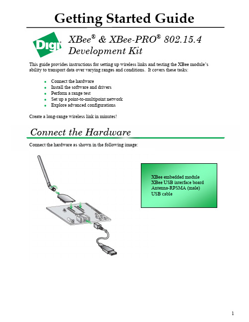
1Getting Started GuideThis guide provides instructions for setting up wireless links and testing the XBee module’s ability to transport data over varying ranges and conditions. It covers these tasks:Connect the hardwareInstall the software and drivers Perform a range testSet up a point-to-multipoint network Explore advanced configurationsCreate a long-range wireless link in minutes!Connect the hardware as shown in the following image:XBee ® & XBee-PRO ®802.15.4 Development KitConnect the HardwareInstall the Software and DriversInstall X-CTU SoftwareX-CTU is a stand-alone tool for configuring XBee modules. It can also be used to run a rangetest.To install X-CTU:1. Download X-CTU at /xctu.2. Browse to the folder to which you saved the above install file.3. Double-click on the installer file and follow the X-CTU Setup Wizard.4. When asked if you would like to check Digi's web site for firmware updates, click Yes.5. After the firmware updates are complete, click Close. Updates may take a few minutes; pleasebe patient.6. Start X-CTU by double-clicking on the X-CTU icon on your desktop, or by selecting Start >Programs > Digi > X-CTU.Install USB DriversThe XBee USB interface board is a "plug‐and‐play" device that should be detected by the PCautomatically. If you are using Windows 7 or Vista, the USB drivers should automatically install and a notification will appear in the lower right portion of your screen indicating success orfailure. If the USB drivers fail to install, please follow the USB driver installation instructionsfound here: /support/kbase/kbaseresultdetl.jsp?id=3214.If you are using Windows 2000 or XP, download and install the driver as per the followingdirections.To install the USB driver:1. Download the driver setup file at:/support/driver/FTDI_Windows_Driver_Setup.exe.2. Double‐click on the setup file. A window will pop up during installation and automaticallyclose when the process is complete. The USB interface board may now be connected to thecomputer.2Perform Range TestRun Range Testunch the X-CTU Software: Start > Programs > Digi > X-CTU2.Under the PC Settings tab, select the PC serial COM port that will be used. The USB portswill be labeled as Digi PKG-U Serial Port Adapters and are assigned a number based on yourPC's settings.3.Verify that the baud rate and data settings match the internal settings of the radios. Thedefault settings for the radios are Baud Rate: 9600, Flow Control: HARDWARE, Data Bits:8, Parity: NONE, and Stop Bits: 1.344. Select the Range Test tab.5. (Optional) Check the RSSI checkbox to enable the Received Signal Strength Indicator. The RSSI value indicates the signal strength of the last packet that the radio received.6. Click Start to begin the range test.7. Monitor the link quality by reading the Percent section on the Range Test tab. This section displays the running percentage of good packets sent to the receiving radio and looped back to the base.8. Click Stop to end the range test.Set up a Point-to-Multipoint NetworkRF Module ConfigurationThis section requires changing some of the radio’s internal settings. One simple method forconfiguration is as follows. In the X-CTU Modem Configuration tab, click Read . Select any of the module parameters you wish to change (e.g. Address, Encryption, etc.) and type in or select the desired value. Then click Write to save the changes to non-volatile memory.This is one of several configuration methods. Refer to the product manual for more information. To restore the module back to defaults, click Restore .Point-to-Multipoint AddressingPoint-to-multipoint topologies require one base module to be configured to operate in Broadcastmode (DL= 0xFFFF). This allows the module to broadcast messages to all devices in thenetwork.Remote modules can operate either in Broadcast or Unicast mode. Unicast mode is used whenyou want to send a message directly from one module to another. To do so, you set theDestination Address High (DH) of the sender to zero and the Destination Address Low (DL) ofthe sender to match the 16-bit Source Address (MY) of the recipient. The figure below depicts atypical point-to-multipoint network that contains one base and four remotes and their associated settings.Figure 4. Point-to-Multipoint Settings5Explore Advanced ConfigurationsConfigure Remote ModulesThe XBees can also be configured "over-the-air" using X-CTU. In order to use this feature, your base device must be configured for API mode.To send “over-the-air” commands:1.Go to the Modem Configuration tab and click the Remote Configuration option at the topof the window.2.Click Open Com Port and Discover from the menu bar at the top of the Network window.A list of all of the nodes in the network will populate the screen.3.Select a particular node from the list. You can interact with it as if it was connected to the PCdirectly.4.Click Read, Write, or Restore parameters on the main X-CTU window and those changeswill occur over the air on the remote module selected in the Network window.5.Close the Network window when you have finished with remote configuration.6Change Firmware VersionThese modules can also be set up for mesh communications. In some cases, a mesh solution maybe a better option. DigiMesh TM is better for networks needing routing capabilities. Also,DigiMesh provides the option for all the radios in the network to sleep synchronously. If youwant to try mesh mode, you can simply load different firmware on your XBees.These steps can also be used to update to the latest version of point-to-multipoint firmware.X-CTU is used to load different firmware on a locally connected radio.unch X-CTU and select the corresponding COM Port.2.Set the PC settings back to default. (Baud Rate: 9600, Flow Control: HARDWARE, DataBits: 8, Parity: NONE, Stop: Bits 1)3.Click on the Modem Configuration tab.4.Select the modem type. Choose XB24-DM or XBP24-DM to convert an XBee or XBee-PRO 802.15.4 module into a DigiMesh XBee or XBee-PRO 2.4 module. Leave the modemtype as XB24 or XBP24 to just update the point to multipoint firmware.5.Choose the Function Set and firmware Version desired.6.Click the Show Defaults button. This helps to avoid out of range errors since someparameters have different limits based on the firmware type.7.Check the Always update firmware box.8.Click Write.78End-to-End ConnectivityThese XBee modules are part of a family of cohesive devices. Digi’s Drop -in Networking solutions are designed to provide end-to-end wireless connectivity to distributed electronic devices so those devices can be accessed and managed from anywhere. Specifically Digi offers RF-to-Internet gateways that allow remote monitoring and control of an RF network. For more information about Digi gateways, see /products/wireless-routers-gateways .On a larger scale, multiple gateways controlling separate RF networks can be managed through our iDigi cloud services. The image above shows a secure connection to your devices through an iDigi account. Learn more about managing your remote devices at .Contact Digi InternationalFigure 7. Point-to-Multipoint。
XBee-PRO 900 嵌入式 RF 模块说明说明书
XBee-PRO 900embedded RF modules combine fast point-to-multipoint networking with the RF range advantages of 900MHz technology.Built upon a 156Kbps RF platform,these modules are ideal for applications requiring low latency and increased data throughput.With RF line-of-sight (LOS)distances of up to six miles with a high gain antenna,XBee-PRO 900embedded RF modules are also ideal in applications where devices are distributed over great distances.XBee ProtocolsXBee embedded RF modules are available with different protocols to suit a variety ofapplications and networking topologies.Supported protocols include IEEE 802.15.4,the ZigBee PRO Feature Set,proprietary long range,and DigiMesh™.XBee modules share a common hardware footprint and are modeled after a common software API.Once deployed into an application,OEMs can rapidly change from one protocol to another with minimal time and development risk.Drop-in Networking CompatibilityXBee embedded RF modules are compatible with Digi’s Drop-in Networking adapters,network extenders and gateways that use the same protocol.This allows OEMs to embed XBee solutions into an application and have seamless communication to other devices using USB,RS-232,RS-485,digital I/O,analog I/O,Ethernet,Wi-Fi and cellular IP with plug-and-play ease.XBee-PRO900modules deliver 900MHz extended-range end-point connectivity using a fast point-to-multipoint protocol.Features/Benefits• 1.8miles/3km RF LOS range with 2.1dB dipole antenna •6miles/10km RF LOS range with high-gain antenna •Fast 156Kbps data rate to the end node •Supports sleep modes for increased battery life •Capable of deploying the DigiMesh protocol with a simple firmware change •Over-the-air configuration •Interoperable with Digi Drop-in Networking products utilizing XBee-PRO 900technology,including device adapters and gateways •Common XBee footprint for a variety of RF modules •Multiple antenna options •Industrial temperature rating (-40ºC to +85ºC)Point-to-Multipoint Embedded RF Modules for OEMs Product DatasheetOverviewXBee-PRO ®900Central Fitness ManagementEthernetConnectPort XGateway Wireless Telco NetworkInternet/Frame Relay/VPNFitness CenterCommunication SystemWorkout InfoEquipment Health InfoEntertainmentInfoXBee-PRO Module EntertainmentServicesMaintenance IndicatorTimerPulse GaugeOdometerVibrationPower ConsumptionPort wa yFitness EquipmentCom m CoC mu Sy Sys -P R O ulee91001475A2/708©2008Digi International Inc.All rights reserved.Digi,Digi International,the Digi logo,the When Reliability Matters logo,DigiMesh,XBee and XBee-PRO are trademarks or registered trademarks of Digi International Inc.in the United States and other countries worldwide.All other trademarks are the property of their respective owners.Digi Internationa l11001Bren Road E.Minnetonka,MN 55343U.S.A.PH:877-912-3444952-912-3444FX:952-912-4952email:*************Digi Internationa l France31rue des Poissonniers 92200Neuilly sur Seine PH:+33-1-55-61-98-98FX:+33-1-55-61-98-99www.digi.frDigi Internationa l KKNES Building South 8F 22-14Sakuragaoka-cho,Shibuya-kuTokyo 150-0031,Japan PH:+81-3-5428-0261FX:+81-3-5428-0262www.digi-intl.co.jpDigi Internationa l (HK)LimitedUnit 3206–08A,32/F ,AIA Tower183Electric Road,North Point,Hong Kong PH:+852-2833-1008FX:+DIGI SERVICE AND SUPPORT -You can purchase with confidence knowing that Digi is here to support you with expert technical support and a one-year warranty./supportDigi International ,the leader in device networking for business,develops reliable products and technologies to connect and securely manage local or remote electronic devices over the network or via the web.With over 20million ports shipped worldwide since 1985,Digi offers the highest levels of performance,flexibility and quality.Please visit for part numbers.。
XBee-PRO SX RF Modem 用户指南说明书

XBee Radio Frequency(RF)Modems XBee-PRO SX RF ModemFeedbackTo provide feedback on this document,email your comments to*****************Include the document title and part number(XBee RF Modems User Guide,90001517C)in the subject line of your email.Hardware Front view(RS-232/RS-485variant)CAUTION!The RJ-45port is only for RS-232/RS-485connections.If you plug in any Powerover Ethernet(PoE)connection,it will damage the port.Hardware Front view(Analog/Digital I/O variant) Number FunctionRSSI LEDsRSSI LEDs indicate the amount of fade margin present in an active wireless link.Fade margin is the difference between the incoming signal strength and the modem's receiver sensitivity.3LEDs ON=Very Strong Signal(>30dB fade margin)2LEDs ON=Strong Signal(>20dB fade margin)1LED ON=Moderate Signal(>10dB fade margin)0LEDs ON=Weak Signal(<10dB fade margin)I/O and associate LEDsLEDs indicate RF modem activity as follows:Top LED(Yellow)=Serial Data OutMiddle LED(Green)=Serial Data InBottom LED(Red)=Associate Indicator(blinks when associated)USB Mini-B portThe USB Mini-B is to serve as a configuration port.Note that when the USB is plugged in,all RS-232 and RS-485communications on the RS-232/RS-485variant are disabled.DIP switchFor the RS-232/RS-485variant,these switches control the120Ωtermination for the receiving differential pairs in the RS-485mode.If the switch is in the up position,the RX termination is enabled. Switch1is for2-wire termination and Switch2is for4-wire termination.Do not enable these switches in RS-232mode.For the Analog/Digital I/O variant,these switches control pull-up outputs on pins5and6of the10-pin header.When the switch is in the up position,a10kΩpull-up to3.3V is enabled.If any other voltage besides3.3V is desired,an external pull-up is required.Do not enable these switches when digital inputs are desired.Reset and Commissioning buttonsThe top button is the Reset Button.The reset button resets,or re-boots the XBee RF Modem.The bottom button is the commissioning push button.It provides a variety of simple functions to aid in deploying devices in a network.See Commissioning Pushbutton behavior for information on how to use this.Antenna PortThe antenna port is a50ΩRF signal connector for connecting to an external antenna.The connector type is RPSMA(Reverse Polarity SMA)female.The connector has threads on the outside of a barrel and a male center conductor.Getting started with the XBee RF Modem Kit requirements Kit requirementsSystem requirementsThe software mentioned in this guide is compatible with the following operating systems:n Windows Vista or higher(32-bit or64-bit versions)n Mac OS X v10.6and higher versions(64-bit version only)n Linux with KDE or GNOME window managers(32-bit or64-bit versions)Additional requirementsThis guide assumes the use of at least two XBee RF Modems.It also assumes that you ordered twoaccessories kits along with the modems.Identify the kit contentsIf you ordered the accessories kit,it should include the following:Mini USB cablePower supplyRPSMA antennaDB9to RJ45adapterRJ45cableThis guide describes connecting and interacting with the USB and the RS-232ports on the XBee RFModem.If you want to connect to the RS-485protocol,see Interfacing protocols.Connect to the USB portIn order to properly connect the modem for this guide:Getting started with the XBee RF Modem Connect to the RS-232port1.Connect the antenna to the RPSMA connector on the XBee RF Modem.2.Plug the12V power supply into the power jack.3.Connect the mini USB cable from a PC to the USB port on the RF Modem.Connect to the RS-232portIn order to properly connect the modem for this guide:1.Connect the antenna to the RPSMA connector on the XBee RF Modem.2.Plug the12V power supply into the power jack.3.Connect the DB9to RJ45adapter to the serial port on your PC.4.Connect the RJ45cable from the adapter to the RJ45port on the RF Modem.Getting started with the XBee RF Modem Configure the device using XCTUConfigure the device using XCTUXBee Configuration and Test Utility(XCTU)is a multi-platform program that enables users to interact with Digi radio frequency(RF)devices through a graphical interface.The application includes built-in tools that make it easy to set up,configure,and test Digi RF devices.For full support of the XBee RF Modem,you must use XCTU version6.3.0or higher.For instructions on downloading and using XCTU,see the XCTU User Guide.Click Discover devices and follow the instructions.XCTU should discover the connected XBee RFModems using the provided settings.Click Add selected devices.The devices appear in the Radio Modules list.You can click a module to view and configure its individual settings.For more information on these items,see AT commands.Discover local XBee RF ModemsXCTU can discover radio modules that are connected directly to your computer.You can use thediscovery tool if you do not know the serial configuration of your XBee RF Modem,do not know the port it is connected to,or want to add multiple modules at once.1.Click the Discover radio modules button on the XCTU toolbar.The Discover radiomodules dialog box opens.4.Click Finish to initiate the discovery scan.A new dialog opens,displaying devices found and estimated time remaining.You can clickStop to halt the discovery process at any time.For example,you can stop the process if the modules you were looking for are already found.Getting started with the XBee RF Modem Configure a networkmode.list(Modembutton toGetting started with the XBee RF Modem Software libraries6.Select the DH(Destination Address High)of Modem1and type the SH of Modem2.7.Select the DL(Destination Address Low)of Modem1and type the SL of Modem2.8.Repeat steps6and7for Modem2.9.Click the Write button.This saves the settings to the modem.10.Select Serial console from the Tools drop-down menu on the main XCTU toolbar.Open aserial console for each modem.e the Console log section to type messages.Type Hello in one of the consoles.It shouldappear in the other console.This shows you have a basic network connected. Software librariesOne way to communicate with the XBee RF Modem is by using a software library.The librariesavailable for use with the XBee RF Modem include:n XBee Java libraryn XBee Python libraryThe XBee Java Library is a Java API.The package includes the XBee library,its source code and acollection of samples that help you develop Java applications to communicate with your XBeedevices.The XBee Python Library is a Python API that dramatically reduces the time to market of XBee projects developed in Python and facilitates the development of these types of applications,making it an easy process.WARNING!When operating at1W power output,observe a minimum separation distance of6ft(2m)between devices.Transmitting in close proximity of other devices can damage the device's front end.Operation Commissioning Pushbutton behaviorn Digital inputn Digital sinking driver outputThis section introduces XBee module concepts and commands.See the product manual for your XBee module for additional information.RS-232operationThe RS-232/RS-485variant of the XBee RF Modem defaults to RS-232mode.If the modem is not set to RS-232mode,set D2(DIO2/AD2)to0(default)or4.D3(DIO3/AD3)does not matter,but we recommend setting it to0(default).Set D7(DIO7/CTS)to1(CTS enabled,default).You can use the USB port to configure RS-232mode,but when it is plugged in the RS-232protocol does not function. RS-232wiring diagramsThe following diagram shows an RS-232DTE device wired to a DCE XBee RF Modem.The following diagram shows a DCE XBee RF Modem wired to a DCE RS-232device.The following diagram shows a sample wireless connection:DTE<-->DCE DCE<-->DCERS-485(2-wire)half-duplex operationTo set the RS-232/RS-485variant of the XBee RF Modem to RS-485(2-wire)half-duplex mode,set the D2and D3commands to5and the D7command to7.The USB port can be used to configure the RS-485(2-wire)mode,but while it is plugged in the RS-485(2-wire)protocol will not function.RS-485(2-wire)wiring diagramRS-485(4-wire)full-duplex operationTo set the RS-232/RS-485variant of the XBee RF Modem to RS-485(4-wire)full-duplex mode,set the D2command to5,the D3command to4,and the D7command to7.The USB port can be used to configure the RS-485(4-wire)mode,but while it is plugged in the RS-485(4-wire)protocol will not function.This mode can also communicate with RS-422devices,if desired.RS-485(4-wire)wiring diagramRS-485connection guidelinesThe RS-485/422protocol provides a solution for wired communications that can tolerate high noise and push signals over long cable lengths.RS-485/422signals can communicate as far as4000feet (1200m).RS-232signals are suitable for cable distances up to100feet(30.5m).RS-485offers multi-drop capability in which you can connect up e the RS-422protocol for point-to-point communications.To integrate the XBee RF Modem with the RS-485protocol,we suggest the following:Regulatory information FCC(United States) FCC(United States)FCC Part15Class BRadio Frequency Interface(RFI)(FCC15.105)This device has been tested and found to comply with the limits for Class B digital devices pursuant to Part15Subpart B of the FCC rules.These limits are designed to provide reasonable protection against harmful interference in a residential environment.This equipment generates,uses,and can radiateradio frequency energy,and if not installed and used in accordance with the instruction manual,may cause harmful interference to radio communications.However,there is no guarantee that interference will not occur in a particular installation.If this equipment does cause harmful interference to radio or television reception,which can be determined by turning the equipment off and on,the user isencouraged to try to correct the interference by one or more of the following measures:n Reorient or relocate the receiving antenna.n Increase the separation between the equipment and receiver.n Connect the equipment into an outlet on a circuit different from that to which the receiver is connected.n Consult the dealer or an experienced radio/TV technician for help.Labeling requirements(FCC15.19)This device complies with Part15of FCC rules.Operation is subject to the following two conditions:(1)this device may not cause harmful interference,and(2)this device must accept any interferencereceived,including interference that may cause undesired operation.Modifications(FCC15.21)Changes or modifications to this equipment not expressly approved by Digi may void the user’sauthority to operate this equipment.Regulatory information ISED(Innovation,Science and Economic Development Canada) ISEDCAUTION!This equipment is approved for mobile and base station transmitting devices only.Antenna(s)used for this transmitter must be installed to provide a separation distance of atleast34cm from all persons and must not be co-located or operating in conjunction with anyother antenna or transmitter.Attention Cetéquipement est approuvépour la mobile et la station base dispositifsd'émission seulement.Antenne(s)utilisépour cetémetteur doitêtre installépour fournirune distance de séparation d'au moins34cmàpartir de toutes les personnes et ne doitpasêtre situéou fonctionner en conjonction avec tout autre antenne ouémetteur.XBee RF Modems User Guide42XBee RF Modems User Guide43Troubleshooting Reset the XBee RF Modem XBee RF Modems User Guide 44Reset the XBee RF ModemIf the XBee RF Modem loses its connection to the computer,you can attempt a reset.ConditionThe XBee RF Modem loses connection to the computer.SolutionEach XBee RF Modem has a reset button.The following image shows the location of the reset button as 1,the topbutton.Press this button to reset the module.However,this will not clear any changes written to the module.You can also press the reset button to reset the COM port for the board.To reconnect the module after pressing the reset button:1.In XCTU,click the Consoles working mode button on thetoolbar .2.Click the Closebutton .3.Click the Open button to restore theconnection .。
zigbee技术XBEE模块使用说明书

XBee和XBee - PRO OEM RF模块的设计,以ZigBee协议内运作,支持低成本的独特需求,低功耗无线传感器网络工程。
模块只需要最小的功率,就能提供远程设备之间的数据传输的可靠性。
这两个模块内运作的ISM 2.4 GHz频段,且引脚对引脚相互兼容。
1.1 主要特点先进的网络和安全重试和确认。
DSSS(直接序列扩频)每一个序列频道,可使用超过65000个唯一的网络地址点至点,点对点,点对多点和点对点的对等拓扑支撑自行安排,自我修复和故障容错网络易于使用没有配置必要的外箱射频通信AT和API命令模式配置模块参数小尺寸广泛的命令集免费的X - CTU软件(测试和配置软件)免费及无限技术支持1.1.1. 全球认证FCC认证(美国)参见附录A [p34要求]。
系统包含的XBee / XBee-PRO射频模块继承MaxStream的认证。
ISM(工业,科学和医疗)2.4吉赫频带的ISO 9001:2000认证机构认证下制造的注册标准的XBee / XBee-PRO射频模块列表被优化用于在美国,加拿大,澳大利亚,以色列和欧洲。
1.2.描述表1-01,XBee/XBee‐PRO OEM RF 模块(简述)当在欧洲运用时:XBee - PRO RF模块必须被配置为运行在一个最大发射功率为10 dBm的输出水平。
电源输出级别设置使用PL 命令。
PL参数必须等于“0”(10 dBm)。
此外,欧洲法规规定,EIRP最高功率为12.86 dBm的(19毫瓦),对于XBee – PRO的12.11 dBm和XBee时高增益天线天线选项:指定的范围内使用时是典型的集成块(1.5 dBi的)和偶极子(2.1 dBi的)天线。
该芯片天线选项提供要素优势,它的形式,但它通常会产生更短的选择范围比带和偶极子天线发射时,在户外。
1.3.机械尺寸图1 - 01 XBee / XBee - PRO OEM RF模块的机械尺寸(天线选项未显示)The XBee and XBee‐PRO RF Modules are pin‐for‐pin compatible.XBee和XBee - 专业射频模块的引脚- 为- 引脚兼容。
- 1、下载文档前请自行甄别文档内容的完整性,平台不提供额外的编辑、内容补充、找答案等附加服务。
- 2、"仅部分预览"的文档,不可在线预览部分如存在完整性等问题,可反馈申请退款(可完整预览的文档不适用该条件!)。
- 3、如文档侵犯您的权益,请联系客服反馈,我们会尽快为您处理(人工客服工作时间:9:00-18:30)。
XBee® Drop-in Networking AccessoriesUser’s GuideXBee RS-232 AdapterXBee RS-485 AdapterXBee Analog I/O AdapterXBee Digital I/O AdapterXBee USB AdapterXStickXBee Wall RouterXBee Smart PlugXBee Sensors90000891_C©2009 Digi International Inc. All Rights Reserved.Digi, Digi International, the Digi logo, ConnectPort, Watchport, XBee, and XBee-PRO are trademarks or registered trademarks of Digi International, Inc. in the United States and other countries worldwide.All other trademarks are the property of their respective owners.Information in this document is subject to change without notice and does not represent a commitment on the part of Digi International.Digi provides this document “as is,” without warranty of any kind, either expressed or implied, including, but not limited to, the implied warranties of fitness or merchantability for a particular purpose. Digi may make improvements and/or changes in this manual or in the product(s) and/or the program(s) described in this manual at any time.This product could include technical inaccuracies or typographical errors. Changes are periodically made to the information herein; these changes may be incorporated in new editions of the publication.C o n t e n t s Chapter 1General information (4)About this guide (4)Additional product information and resources (5)Hardware changes between 9-30V and 3-6V adapter models (6)Powering options for adapters (6)Antenna considerations (7)Product compatibility and differences among XBee RF protocols (8)Compatibility (8)Product support and availability by XBee RF protocol (8)Network association (9)Commissioning and identity behaviors (10)Power levels of XBee radios (13)Duty cycle for XBee 868 module (15)Chapter 2XBee RS-232 Adapter (16)Chapter 3XBee RS-485 Adapter (19)Chapter 4XBee Analog I/O Adapter (23)Chapter 5XBee Digital I/O Adapter (31)Chapter 6XBee USB Adapter (39)Chapter 7XStick (41)Chapter 8XBee Wall Router (43)Chapter 9XBee Smart Plug (46)Chapter 10XBee Sensors (51)Chapter 11Configure XBee RF module settings (54)Configuration with a ConnectPort X gateway (54)Configuration without a gateway (59)Chapter 12Hardware specifications (60)XBee Adapters (60)XStick (62)XBee Wall Router (64)Integrated sensors for XBee Wall Router (65)XBee Smart Plug (66)Integrated sensors for XBee Smart Plug (67)XBee Sensors (68)Integrated sensors for XBee Sensors (68)Chapter 13Safety statements (69)Chapter 1G e n e r a l i n f o r m a t i o n This section includes information that applies to allXBee®Drop-in Networking Accessories.About this guideThis guide describes the features and functions of allXBee Drop-in Networking Accessories for all XBee module protocols,including adapters, routers, sensors, and associated products.It includes connection and setup information, pinouts, configuration, dataretrieval, and LEDs and buttons.Software programming for XBee Drop-in Networking Accessories iscovered on product pages within the Digi Developer Community Wiki; seenext page for more information and location of these pages.Questions and technical supportFor technical assistance with your product, contact Digi Technical Supportat: 877-912-3444 or make an online support request at:/support/index.jspAdditional product information and resourcesProduct data sheets, user’s guides, and product manualsLocate more information, including datasheets, XBee product manuals,ConnectPort X gateway product information, etc. on these pages:/products/wirelessdropinnetworking//din/docsSoftware development resourcesDigi provides several resources to help you get started developing softwaresolutions in Python:Digi Developer Community WikiThe Digi Developer Community Wiki is a place to learn about developingsolutions using Digi's communications portfolio, software and services,including Python, iDigi Platform, iDigi Dia, and more./wiki/developer/index.php/Main_PageEach product’s chapter shows the link to the Wiki page for programmingthe product. For an index page for all XBee Drop-in NetworkingAccessories, go to:/wiki/developer/index.php/Category:Drop-in_Networking_ProductsDigi Python Custom Development Environment pagePython is a dynamic, object-oriented language for developing softwareapplications, from simple programs to complex embedded applications.Python functions can be used to obtain data from attached and integratedsensors on XBee Drop-in Networking Accessories. Find this page at:/technology/drop-in-networking/python.jspDigi Python Programming Guide (90000833)This guide introduces the Python programming language by showing howto create and run a simple Python program. It reviews Python modules,particularly modules with Digi-specific behavior. It describes how to loadand run Python programs onto Digi devices, either through the command-line or web user interfaces, and how to run several sample Pythonprograms. Find this guide at the Digi Python Wiki page--in the Start Heresection, click the link titled Digi Python Programmer's Guide/wiki/developer/index.php/Python_WikiPython Support Forum on Find answers to common questions and exchange ideas and exampleswith other members of the Digi Python development community at:/support/forum/forum.jspa?forumID=104Hardware changes between 9-30V and 3-6V adapter modelsXBee Adapters have undergone some hardware changes since first beinglaunched. Most of the these changes are minor and will have no impact onyour application. However, one important difference relates to supplyvoltage.Originally, XBee Adapters were designed to accept 9-30VDC. In an effort toimprove battery performance, this voltage range has been changed to 3-6VDC.Power supplies used on 9-30VDC XBee Adapters will not work with3-6VDC XBee Adapters, and vice versa. Your XBee Adapter’s propervoltage is printed next to its power port.Plugging in a power supply with the incorrect voltage will damage yourdevice and void your warranty.Several other changes have been implemented in the 3-6VDCXBee Adapter models, including an improved screw-lock connector forXBee RS-485, XBee Digital I/O, and XBee Analog I/O Adapters, andexternal antennas for XBee-PRO Adapters. Contact Technical Support formore details.Powering options for adaptersSome Drop-in Networking Accessories; including the XBee Sensor, XBeeSmart Plug and XBee Wall Router all have necessary powering optionsincluded.XBee Adapter products can be powered by an external power supply orbatteries, purchased separately. To determine how to power your XBeeAdapter, please refer to the specification printed on the side of theenclosure , close to the power port:For additional information, see "Power requirements" on page 60. SpecificationPower Options 3 to 6 VDC Power supply: must be rated 3 to 6 VDC. Digi part number for 5V power supply: XA-ACC-PS5-NRBattery: uses custom lithium battery pack; Digi part number: XA-ACC-CS-L Replacement batteries available for purchase; contact Digi at 952-912-3444.9 to 30 VDCPower supply: must be rated 9 to 30 VDC.; Digi part number for 9V power supply: XA-ACC-PSBattery: uses quantity 3 of 1.5V “N-Cell” alkaline batteries. Can use standard, off-the-shelf, batteries, or Digi part number: XA-ACC-BATTTo install batteries, insert a screwdriver in the slots in the side of the adapter case and twist to snap off the cover. Insert the batteries following the polarity diagram on the board.Warranty exception for batteriesSome XBee Drop-in Networking Accessories ship with alkaline batteriesthat must be replaced by the user when discharged.Lithium batteries must be installed or replaced by qualified servicepersonnel.Alkaline and lithium batteries are not covered under the terms andconditions of the Digi warranty.Antenna considerationsProducts with external antennas should be mounted with the antennaoriented vertically to maximize the range.Products with external antennas use RPSMA antenna connectors.Products without external antennas can be mounted in any orientation.Product compatibility and differences among XBee RF protocolsXBee Drop-in Networking Accessories contain an XBee or XBee-PROmodule, an RF module that performs the wireless communications for yourproduct. Certain RF module behaviors vary by XBee RF protocol. Thissection describes those differences and how they affect product operation.CompatibilityDrop-in Networking Accessories that a particular XBee RF protocol arecompatible with other products that use the same XBee RF protocol only.XBee ZB products will only work with other XBee ZB products, XBee802.15.4 products with other XBee 802.15.4 products, and so on. Thisapplies to gateways as well: ConnectPort X gateway products with anXBee ZB module are compatible with other such gateways, 802.15.4gateways with other such gateways, and so on. Users must standardize onone XBee RF protocol series for operability.Product support and availability by XBee RF protocolProduct availability varies by XBee RF protocol. The table shows the XBeeDrop-in Networking Accessories available for each XBee platform.XBee-PRO 868 availabilityXBee-PRO 868 adapters are available for use in Europe only. Please seethe XBee-PRO 868 OEM RF Modules Product Manual from moreinformation.ProductXBee ZB XBeeZNet2.5a XBee 802.15.4XBee 868XBee DigiMesh900XBee RS-232 Adapter33333XBee RS-485 Adapter33333XBee Analog I/O Adapter33333XBee Digital I/O Adapter33333XBee USB Adapter33 XStick333XBee Wall Router33XBee Smart Plug33XBee Sensors33 XBee Display 33a.New customer deployments should not use the ZNet 2.5 protocol. Instead, use the ZigBee-certified ZB protocol. ZNet, an older protocol based on a “Designed for ZigBee” stack, should only be used where required forcompatibility with previously deployed ZNet 2.5 products.Network associationThe Assc LED indicates the network association status for anXBee Drop-in Networking Accessory in an XBee network.XBee ZB / XBee ZNet 2.5Products used in networks that use a coordinator for network association,the Assc LED indicates network association status as follows:XBee 802.15.4 / XBee 868Products used in networks that do not use a coordinator for networkassociation are not set up to associate, but are configured with a defaultPAN ID and destination address. To maintain LED consistency, onpower-up, these products immediately indicate association by blinking.For more information regarding association options, see the productmanual for the XBee module in your product.XBee DigiMesh 900Products that have been configured in a cyclic sleep-compatible mode usethe Assc LED to indicate the status of the nodes synchronization with thesleeping network. Products that are not configured for sleep use the AsscLED to indicate that they are operating properly.LED statusNetwork association On, solid greenNot associated On, blinking green Successfully joined Sleepcompatible?LED Status Meaning NoOn, blinking green Product is powered and operating properly.YesOn, solid green Product has not synchronized with the network or has lost synchronization with the network.YesOn, slow blinking green (500 mSec blink time)Product is acting as the network sleep coordinator and is operating properly.Yes On, fast blinking green (250 mSec blink time)Product is properly synchronized with the network.Commissioning and identity behaviorsThe Ident button, or, on some products, a combined Reset/Ident button,performs multiple functions to identify and configure the product in an XBeenetwork. The location of this button is shown in each product’s chapter.Button presses and actions for each XBee RF protocol vary follow. Thesedescriptions introduce XBee module concepts and commands. Foradditional information on these concepts and commands, see the productmanual for your XBee module.Consecutive button presses must occur within 800 milliseconds of eachother to perform the desired action.XBee ZB / XBee ZNet 2.5Button pressNetworkassociationAction1Associated If XBee module is asleep, wakes unit for 30 seconds. Sends a Node Identificationbroadcast transmission. All devices that receive this transmission will blink theirAssociate LED rapidly for 1 second. All API devices that receive thistransmission will send a Node Identification frame out their UART (universalasynchronous receiver/transmitter) (API ID 0x95).Unassociated If XBee module is asleep, wakes unit for 30 seconds, then blinks the AI code, anumeric error code on the Assc LED indicating the cause of join failure.1 blink: Scan found no networks (PANs) to join.2 blinks: Scan found no valid PANs based on current settings forSC(Scan Channel) and ID (PAN ID).3 blinks: Valid coordinator or routers were found, but they are not allowingjoining, because the permit join or NJ command expired.7 blinks: Network joining attempt failed.10 blinks: Coordinator Start attempt failed.2Associated Depends on the setting for the permit join (NJ) command for the XBee module.If the XBee module’s NJ command setting is less than 255, two button pressestemporarily enable joining on the XBee module and on the entire XBee networkfor 1 minute.If joining is permanently enabled on a module (NJ = 255), joining remainspermanently enabled, and two button presses have no effect.4Associated/Unassociated XBee module leaves PAN, if associated, and issues a factory reset to restore default parameters in the XBee module.For XBee ZNet 2.5, the default PAN ID is 0x234.For XBee ZB, the default PAN ID is 0 (join any network).XBee 802.15.4Button pressNetworkassociationAction1Associated Cannot wake module, but causes module to remain awake for 30 seconds ifpressed during a sleep interval.Sends a Node Identification broadcast transmission. All devices that receive thistransmission will blink their Associate LED rapidly for 1 second.Unassociated Blinks a numeric error code returned by the ATAI (Association Indication)command on the Assc LED. The AI code indicates the cause of the join failure.See the 802.15.4 XBee module’s Product Manual for descriptions of thesecodes.1 blink: Active scan timeout.2 blinks: Active scan found no PANs.3 blinks: Active scan found PAN, but the Coordinator Allow Association bit is notset.4 blinks: Active scan found a PAN, but Coordinator and End Device are notconfigured to support beacons.5 blinks: Active scan found a PAN, but Coordinator ID (PAN ID) value does notmatch the ID of the End Device.6 blinks: Active Scan found a PAN, but Coordinator CH (Channel) value doesnot match the CH of the End Device.7 blinks: Energy scan timeout.8 blinks: Coordinator start request failed.9 blinks: Coordinator could not start due to invalid parameters.10 blinks: Coordinator Realignment is in progress.11 blinks: Association request not sent.12 blinks: Association request timed out - no reply was received.13 blinks: Association request had an invalid parameter.14 blinks: Association request channel access failure - Request was nottransmitted - CCA failure.15 blinks: Remote Coordinator did not send an ACK after Association Requestwas sent.16 blinks: Remote Coordinator did not reply to the Association Request, but anACK was received after sending the request.17 blinks: [reserved].18 blinks: Sync-Loss - Lost synchronization with a beaconing coordinator.19 blinks: Disassociated - No longer associated to coordinator.2Associated Not supported.4Associated/UnassociatedPerforms an ATRE command to reset the parameters in the XBee module.XBee DigiMesh 900XBee 868Button pressSleepConfiguration and Synch StatusAction1Not configured for sleepImmediately sends a Node Identification broadcast transmission. All devices that receive this transmission will blink their Associate LED rapidly for 1 second. All API devices that receive this transmission will send a Node Identification frame out their UART (API ID 0x95)1Configured for sleepWakes the module for 30 seconds, or until the entire network goes to sleep. Queues a Node Identification broadcast transmission to be sent at the beginning of the next network wake cycle. All devices that receive this transmission will blink their Associate LED rapidly for 1 second. All API devices that receive this transmission will send a Node Identification frame out their UART (API ID 0x95).2Not configured for sleep Not supported.2Configured for sleepCauses a node which is configured with sleeping router nomination enabled to immediately nominate itself as the network sleepcoordinator. For more information on this action, see the description of the ATSO sleep options command in the XBee module’s Product Manual.4EitherIssues an ATRE command to restore module parameters to default values.Button PressAction1Immediately sends a Node Identification broadcast transmission. All devices that receive this transmission will blink their Associate LED rapidly for 1 second. All API devices that receive this transmission will send a Node Identification frame out their UART (API ID 0x95).2Not supported.4Issues an ATRE command to restore module parameters to default values.Power levels of XBee radiosThe transmit power level (PL setting) varies among XBee RF protocols.XBee ZB / XBee ZNet 2.5XBee moduleXBee-PRO moduleXBee-PRO ZB and ZNet 2.5 modules have a fixed power level that cannot be changed.Power LevelConducted power in dBmLowest (0) -8 dBm Low (1) -4 dBm Medium (2) -2dBm High (3) 0 dBm Maximum (4)+2dBmProduct variantFixed conducted power in dBmNorth American +17 dBm International+10 dBmXBee 802.15.4XBee moduleXBee-PRO moduleXBee DigiMesh 900Output power is always: 17 dBm.XBee 868Power LevelConducted Power in dBmLowest (0)-10 dBm Low (1)-6 dBm Medium (2)-4 dBm High (3)-2 dBm Maximum (4)0 dBmPower LevelNorth AmericanvariantInternational variantLowest (0)+10 dBm -3 dBm Low (1)+12 dBm -3 dBm Medium (2)+14 dBm +2 dBm High (3)+16 dBm +8 dBm Maximum (4)+18 dBm+10 dBmPower LevelConducted Power in dBmLowest (0) 0 dBm Low (1) +13.7 dBm Medium (2) +20 dBm a a.These products are currently set to not exceed this power setting:XBee RS-232 Adapter, XBee RS-485Adapter, XBee Analog I/O Adapter,XBee Digital I/O Adapter.High (3) +22 dBm b b.XBee USB Adapter is currently set to not exceed this power setting.Maximum (4)+25 dBmDuty cycle for XBee 868 moduleThe XBee 868 module has constraints regarding the amount of data it cantransmit during a given time period. The duty cycle of this module is 10%averaged over the period of 1 hour. This means that if the nexttransmission will push the running average duty cycle over the 10% limit,the module will not transmit until enough time has elapsed to stay under theduty cycle. Because of heat restraints of the module, a 10% duty cycle overthe period of 1 second will be enforced after the measured temperature ofthe module rises above 60°C.Chapter 2XBee RS-232 Adapter OverviewThe XBee RS-232 Adapter provides short-range wireless connectivity toany RS-232 serial device. Unlike an embedded wireless module, whichrequires design integration and development time, these off-the-shelfadapters provide instant wireless connectivity to existing RS-232 serialdevices. All XBee adapters can be used with Digi's ConnectPort Xgateways for data aggregation and IP connectivity.Connection and power-on1.Connect the desired device to the RS-232 port of the adapter.2.Connect the power supply to the adapter or insert batteries.PinoutsThe RS-232 connector is an industry-standard DB9 male connector with aDTE configuration, similar to a PC serial port.To connect the XBee RS232 Adapter to another DTE device, use astandard DB9 crossover serial cable similar to Digi part number 76000642.To connect the XBee RS232 Adapter to a DCE device, use astraight-through null modem cable similar to Digi part number63000066-01.Pin 1 is in the leftmost pin on the upper row of pins; pin numbers incrementfrom left to right, continuing left to right on the second row.Pinouts for the connector are:Pin Function Data direction1CD Input2RXD Input3TXD Output4DTR Output5GND6DSR Input7RTS Output8CTS Input9+12VDC switched power out OutputSoftware programming and data retrievalThere are several avenues for programming the adapter.To get started on developing solutions with the XBee RS-232 Adapterusing iDigi, see the iDigi web page:/For details on programming the adapter and retrieving data from it, see theXBee RS-232 Adapter product page on theDigi Developer Community Wiki:/wiki/developer/index.php/XBee_RS-232_Adapter LEDs and buttonsLED/Button FunctionPower LED Indicates that power is on. Illuminated only when adapter is connected to external power only, not when powered by batteries. Not available in lithium-battery models.Assc LED Indicates the adapters’s network association status. This LED functions differentlydepending on the XBee RF protocol for the product. See "Network association" on page9 for more information.Reset button Recessed button on underside of the adapter. Performs equivalent of a power-cycle.Use a small non-conductive tool with a blunt end to press gently and hold down button.Ident button Recessed button on power end of the adapter between Assc and Power LEDs.Performs multiple functions for identifying and configuring the adapter in a wirelessnetwork. Button presses and actions vary by XBee RF protocol; see "Commissioningand identity behaviors" on page 10.Consecutive button presses must occur within 800 milliseconds of each other to performthe desired action.OverviewThe XBee RS-485 Adapter provides short-range wireless connectivity to any RS-485 serial device. Unlike an embedded wireless module, which requires design integration and development time, these off-the-shelf adapters provide instant wireless connectivity to existing RS-485 serial devices. All XBee adapters can be used with Digi's ConnectPort X gateways for data aggregation and IP connectivity.Connection and power-on1.Connect the desired device to the RS-485 port of the adapter.2.Connect the power supply to the adapter or insert batteries.Chapter 3XBee RS-485 AdapterPinoutsThe connector for the adapter is a 6-position wire terminal block. The figure shows Pin 1 of the connector when the adapter is oriented with the mounting tabs, facing upwards (the underside of the adapter).The adapter is switch-selectable between RS-422 half duplex,RS-422full duplex, and RS-485 modes (see "DIP switches" on page 21). The function for several pins varies between RS-422 and RS-485 modes. Using the orientation in the above figure, pin 1 is the right-most pin and pin numbers increment from right to left. Pinouts for the connector are:The connector accommodates wire gauges from 16AWG to 30AWG. To insert wires, insert the wires into the removable screw-lock connector and tighten the screws associated with the wire slots.To remove wires, loosen the screws associated with the wire slots and remove the wires.PinFunction in RS-422 modeFunction in RS-485 mode1TxD+ (RS422)TxD+ and RxD+ (RS485)2TxD- (RS422)TxD- and RxD- (RS485)3RxD+ (RS422)Not used.4RxD- (RS422) Not used.5GroundGround6+12VDC 50mA max switched power out+12VDC 50mA maxswitched power outDIP switchesThe XBee RS-485 Adapter has several DIP switches on the underside of the unit. DIP switch 1 is the leftmost switch. Switch settings are:Software programming and data retrievalThere are several avenues for programming the XBee RS-485 Adapter.To get started on developing solutions with the XBee RS-485 Adapter using iDigi, see the iDigi web page:/For details on programming the XBee RS-485 Adapter and retrieving data from it, see the XBee RS-485 Adapter product page on the Digi Developer Community Wiki:/wiki/developer/index.php/XBee_RS-485_AdapterDIP SwitchSwitch settings1Not used. It is covered up by the case and is not accessible.2, 3, 4 together ON = RS485 OFF = RS4225, 6 togetherON = RS485 bias and line termination on.OFF = RS485 bias and line termination off.Note: Bias and line termination feature can be used only when powering from the external power supply.LEDs and buttonsLED/Button FunctionPower LED Indicates that power is on. Illuminated only when adapter is connected to external power only, not when powered by batteries. Not available in lithium-battery models.Assc LED Indicates the adapters’s network association status. This LED functions differentlydepending on the XBee RF protocol for the product. See "Network association" on page9 for more information.Reset button Recessed button on underside of the adapter. Performs equivalent of a power-cycle.Use a small non-conductive tool with a blunt end to press gently and hold down button.Ident button Recessed button on power end of the adapter between Assc and Power LEDs.Performs multiple functions for identifying and configuring the adapter in a wirelessnetwork. Button presses and actions vary by XBee RF protocol; see "Commissioningand identity behaviors" on page 10.Consecutive button presses must occur within 800 milliseconds of each other to performthe desired action.OverviewThe XBee Analog I/O Adapter provides short-range wireless connectivity to any analog device. Unlike an embedded wireless module, which requires design integration and development time, this off-the-shelf adapterprovides instant wireless connectivity to existing analog devices. All XBee adapters can be used with Digi's ConnectPort X gateways for data aggregation and IP connectivity.The XBee Analog I/O adapter allows for several interfaces to analogdevices. It provides greater flexibility and uses than XBee Sensors, in that it can be used with a variety of off-the-shelf sensor products and in situations when the item being measured or analyzed must be separated from the sensor/measuring device itself.Chapter 4X B e e A n a l o g I /O A d a p t erDeployment decisionsDeploying the XBee Analog I/O Adapter in a solution involves answeringseveral questions:•What is the analog mode of the sensor you plan to attach to theadapter?•How do you want to retrieve measurement data from the adapter?•How will the adapter be powered? Mains or battery?Analog modesThe XBee Analog I/O Adapter has three modes in which it can measureinput on its four terminal lines:•0-10 volt mode: measures voltage on a scale of 1 to 10 volts, andtranslates it into a 10-bit scale from 0 to 1023 as possible values.•Current Loop (4 mA to 20 mA) mode: measures amperage on a scaleof 4 to 20 mA, and translates it into a 10-bit scale from 0 to 1023 aspossible values.•Differential input mode: measures paired terminals (1 and 2 paired, 3and 4 paired) and translates the difference in voltage between the twolines to into a 10-bit scale from 0 to 1023 as possible values.Measurement retrieval optionsThere are several ways to retrieve data collected by the XBee module inthe adapter.•Through the iDigi Dia (Device Integration Application) framework.iDigi Dia software that simplifies connecting devices (sensors, PLCs,etc.) to communication gateways. iDigi Dia includes a comprehensivelibrary of plug-ins that work out-of-the-box with common device typesand can also be extended to include new devices.•By using existing Python modules provided by Digi•By using your own custom Python programs•By issuing remote AT commands from another XBee device。