程工-20100908Forms of Bridge Foundation-CCSHCC-pengyc(英文)
实用土木工程英语 中国建材工业出版社 Unit 9 Foundations

• Stepped Footing. Stepped footings are provided where the ground has a slope, otherwise it becomes uneconomical to provide foundations at the same
Figure 9.1 Isolated footing(left)and combined footing(right)
• (6)What is combined footing?
• (6)什么是联合基础?
• Combined footing is adopted when the space between two columns is so small that the foundation for individual columns will overlap. Combined footings are proportioned in such a way that the centre of gravity of the loads coincides with the centre of gravity of the foundation. Hence, these footings have either a trapezoidal or a rectangular shape. The plan of a combined footing is shown in Figure 9.1(right)
• Earthfast or post in ground construction • 柱坑技术 • Padstones • 承梁垫石 • Stone Foundations • 石头基础 • Rubble Trench Foundations • 碎石沟基础
Bridge engineering handbook桥梁工程手册-61桥梁水力学

61.1 Introduction
This chapter presents bridge engineers basic concepts, methods, and procedures used in bridge hydraulic analysis and design. It involves hydrology study, hydraulic analysis, on-site drainage design, and bridge scour evaluation. Hydrology study for bridge design mainly deals with the properties, distribution, and circulation of water on and above the land surface. The primary objective is to determine either the peak discharge or the flood hydrograph, in some cases both, at the highway stream crossings. Hydraulic analysis provides essential methods to determine runoff discharges, water profiles, and velocity distribution. The on-site drainage design part of this chapter is presented with the basic procedures and references for bridge engineers to design bridge drainage. Bridge scour is a big part of this chapter. Bridge engineers are systematically introduced to concepts of various scour types, presented with procedures and methodology to calculate and evaluate bridge scour depths, provided with guidelines to conduct bridge scour investigation and to design scour preventive measures.
Bridge engineering handbook桥梁工程手册-19斜拉桥
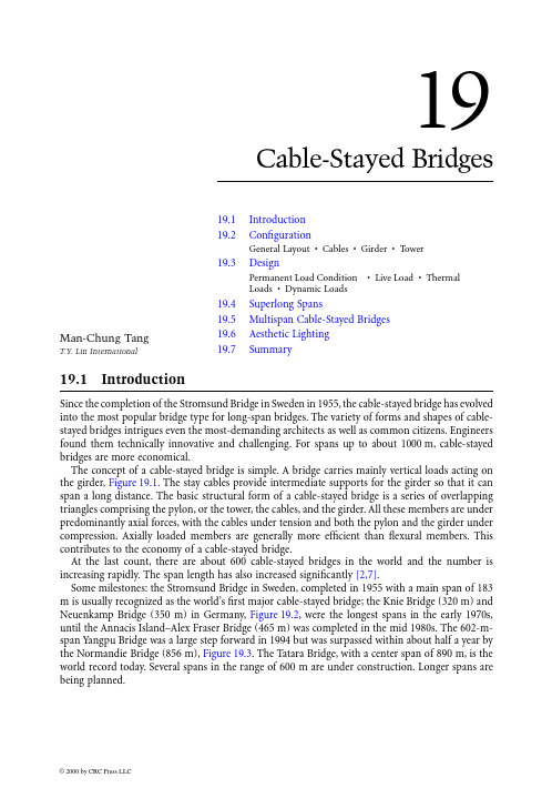
19Cable-Stayed Bridges19.1 Introduction19.2 ConfigurationGeneral Layout •Cables •Girder •Tower19.3 DesignPermanent Load Condition•Live Load •ThermalLoads •Dynamic Loads 19.4 Superlong Spans 19.5 Multispan Cable-Stayed Bridges 19.6 Aesthetic Lighting 19.7SummarySince the completion of the Stromsund Bridge in Sweden in 1955, the cable-stayed bridge has evolved into the most popular bridge type for long-span bridges. The variety of forms and shapes of cable-stayed bridges intrigues even the most-demanding architects as well as common citizens. Engineers found them technically innovative and challenging. For spans up to about 1000 m, cable-stayed bridges are more economical.The concept of a cable-stayed bridge is simple. A bridge carries mainly vertical loads acting on the girder, Figure 19.1. The stay cables provide intermediate supports for the girder so that it can span a long distance. The basic structural form of a cable-stayed bridge is a series of overlapping triangles comprising the pylon, or the tower, the cables, and the girder. All these members are under predominantly axial forces, with the cables under tension and both the pylon and the girder under compression. Axially loaded members are generally more efficient than flexural members. This contributes to the economy of a cable-stayed bridge.At the last count, there are about 600 cable-stayed bridges in the world and the number is increasing rapidly. The span length has also increased significantly [2,7].Some milestones: the Stromsund Bridge in Sweden, completed in 1955 with a main span of 183m is usually recognized as the world’s first major cable-stayed bridge; the Knie Bridge (320 m) and Neuenkamp Bridge (350 m) in Germany, Figure 19.2, were the longest spans in the early 1970s,until the Annacis Island–Alex Fraser Bridge (465 m) was completed in the mid 1980s. The 602-m-span Yangpu Bridge was a large step forward in 1994 but was surpassed within about half a year by the Normandie Bridge (856 m), Figure 19.3. The Tatara Bridge, with a center span of 890 m, is the world record today. Several spans in the range of 600 m are under construction. Longer spans are being planned.Man-Chung TangT.Y. Lin InternationalFIGURE 19.1Concept of a cable-stayed bridge.FIGURE 19.2Neuenkamp Bridge.FIGURE 19.3Normandie Bridge.19.2.1General LayoutAt the early stage, the idea of a cable-stayed bridge was to use cable suspension to replace the piers as intermediate supports for the girder so that it could span a longer distance. Therefore, early cable-stayed bridges placed cables far apart from each other based on the maximum strength of the girder.This resulted in rather stiff girders that had to span the large spacing between cables, in addition to resisting the global forces.The behavior of a cable-stayed girder can be approximately simulated by an elastically supported girder. The bending moment in the girder under a specific load can be thought of as consisting of a local component and a global component. The local bending moment between the cables is proportional to the square of the spacing. The global bending moment of an elastically supported girder is approximately [5](19.1)where a is a coefficient depending on the type of load p, I is the moment of inertia of the girder,and k is the elastic support constant derived from the cable stiffness. The global moment decreases as the stiffness of girder , I, decreases.Considering that the function of the cables is to carry the loads on the bridge girder, which remains the same, the total quantity of cables required for a bridge is practically the same indepen-dent of the number of cables, or cable spacing, Figure 19.4. But if the cable spacing is smaller, the local bending moment of the girder between the cables is also smaller. A reduction of the local bending moment allows the girder to be more flexible. A more flexible girder attracts in turn less global moment. Consequently, a very flexible girder can be used with closely spaced cables in many modern cable-stayed bridges. The Talmadge Bridge, Savannah, Figure 19.5, is 1.45 m deep for a 335m span, The ALRT Skytrain Bridge, Vancouver, Figure 19.6, is 1.1 m deep for a 340 m span and the design of the Portsmouth Bridge had a 84-cm-deep girder for a span of 286 m.Because the girder is very flexible, questions concerning buckling stability occasionally arose at the beginning. However, as formulated by Tang [4], Eq. (19.2), using the energy method,(19.2)where E is modulus of elasticity, I is moment of inertia, A is area, L is length , w is deflection, and ( )′is derivative with respect to length s. The buckling load depends more on the stiffness of the cables than on the stiffness of the girder. Theoretically, even if the stiffness of the girder is neglected, a cable-stayed bridge can still be stable in most cases. Experience shows that even for the most flexible girder, the critical load against elastic buckling is well over 400% of the actual loads of the bridge.FIGURE 19.4Cable forces in relation to load on girder.P cr EIw ds EC Ac Lc Ps Pc w ds ()=′′+∗∗()′ ∑∫∫22The recently adopted design requirement that all cables be individually replaceable makes closely spaced cables more desirable. It is usually required that one cable can be detensioned, dismantled,and replaced under reduced traffic loading. The additional bending moment in the girder will not increase excessively if the cable spacing is small.Availability of ever more powerful computers also helps. The complexity of the analysis increases as the number of cables increases. The computer offers engineers the best tool to deal with this problem.Harp, radial, fan, Figure 19.7, or other cable configurations have all been used. However, except in very long span structures, cable configuration does not have a major effect on the behavior of the bridge.A harp-type cable arrangement offers a very clean and delicate appearance because an array of parallel cables will always appear parallel irrespective of the viewing angle. It also allows an earlier FIGURE 19.5Talmadge Bridge.FIGURE 19.6ALRT Skytrain Bridge.FIGURE 19.7Cable arrangements.start of girder construction because the cable anchorages in the tower begin at a lower elevation.The Hoechst Bridge and the Dames Point Bridge are examples that fully utilized this advantage.A fan-type cable arrangement can also be very attractive, especially for a single-plane cable system.Because the cable slopes are steeper, the axial force in the girder, which is an accumulation of all horizontal components of cable forces, is smaller. This feature is advantageous for longer-span bridges where compression in the girder may control the design. The Nord Bridge, Bonn,Figure 19.8, is one of the first of this type.A radial arrangement of cables with all cables anchored at a common point at the tower is quite efficient. However, a good detail is difficult to achieve. Unless it is well treated, it may look clumsy.The Ludwighafen Bridge, Germany, Figure 19.9, is a successful example. The Yelcho Bridge, Chile,with all cables anchored in a horizontal plane in the tower top, is an excellent solution, both technically and aesthetically.When the Stromsund Bridge was designed, long-span bridges were the domain of steel construc-tion. Therefore, most early cable-stayed bridges were steel structures. They retained noticeable features from other types of long-span steel bridges.In the 1960s, Morandi designed and built several relatively long span concrete cable-stayed bridges. His designs usually had few cables in a span with additional strut supports at the towers for the girder. They did not fully utilize the advantages of a cable-stayed system. The concrete cable-stayed bridge in its modern form started with the Hoechst Bridge in Germany, followed by the Brotone Bridge in France and the Dames Point Bridge in the United States, each representing a significant advance in the state of the art.FIGURE 19.8Nord Bridge.FIGURE 19.9Ludwighafen Bridge.19.2.2CablesCables are the most important elements of a cable-stayed bridge. They carry the load of the girder and transfer it to the tower and the back-stay cable anchorage.The cables in a cable-stayed bridge are all inclined, Figure 19.10. The actual stiffness of an inclined cable varies with the inclination angle, a, the total cable weight, G, and the cable tension force , T [3]:(19.3)where E and A are Young’s modulus and the cross-sectional area of the cable. And if the cable tension T changes from T 1 to T 2, the equivalent cable stiffness will be(19.4)In most cases, the cables are tensioned to about 40% of their ultimate strength under permanent load condition. Under this kind of tension, the effective cable stiffness approaches the actual values,except for very long cables. However, the tension in the cables may be quite low during some construction stages so that their effectiveness must be properly considered.A safety factor of 2.2 is usually recommended for cables. This results in an allowable stress of 45% of the guaranteed ultimate tensile strength (GUTS) under dead and live loads [9]. It is prudent to note that the allowable stress of a cable must consider many factors, the most important being the strength of the anchorage assemblage that is the weakest point in a cable with respect to capacity and fatigue behavior.There have been significant developments in the stay cable system. Early cables were mainly lock-coil strands. At that time, the lock-coil strand was the only cable system available that could meet the more stringent requirements of cable-stayed bridges.Over the years, many new cable systems have been successfully used. Parallel wire cables with Hi-Am sockets were first employed in 1969 on the Schumacher Bridge in Mannheim, Germany.Since then, the fabrication technique has been improved and this type cable is still one of the best cables commercially available today. A Hi-Am socket has a conical steel shell. The wires are parallel for the entire length of the cable. Each wire is anchored to a plate at the end of the socket by a button head. The space in the socket is then filled with epoxy mixed with zinc and small steel balls.The Hi-Am parallel wire cables are prefabricated to exact length in the yard and transported to the site in coils. Because the wires are parallel and therefore all of equal length, the cable may FIGURE 19.10An inclined cable.EA EA G EA a T eff ()=+(){}112223cos EA EA G EA a T T T T eff ()=++()(){}11224122222cossometimes experience difficulty in coiling. This difficulty can be overcome by twisting the cable during the coiling process. To avoid this problem altogether, the cables can be fabricated with a long lay. However, the long lay may cause a very short cable to twist during stressing. Threadbar tendons were used for some stay cables. The first one was for the Hoechst Bridge over the Main River in Germany. The Penang Bridge and the Dames Point Bridge also have bar cables. They all have a steel pipe with cement grout as corrosion protection. Their performance has been excellent. The most popular type of cable nowadays uses seven-wire strands. These strands, originally developed for prestressed concrete applications, offer good workability and economy. They can either be shop-fabricated or site-fabricated. In most cases, corrosion protection is provided by a high-density polyethylene pipe filled with cement grout. The technique of installation has progressed to a point where a pair of cables can be erected at the site in 1 day.In search of better corrosion protection, especially during the construction stage before the cables have been grouted, various alternatives, such as epoxy coating, galvanization, wax and grease have all been proposed and used. Proper coating of strands must completely fill the voids between the wires with corrosion inhibitor. This requires the wires to be loosened before the coating process takes place and then retwisted into the strand configuration.In addition to epoxy, grease, or galvanization, the strands may be individually sheathed. A sheathed galvanized strand may have wax or grease inside the sheathing. All three types of additional protection appear to be acceptable and should perform well. However, a long-term performance record is not yet available.The most important element in a cable is the anchorage. In this respect, the Hi-Am socket has an excellent performance record. Strand cables with bonded sockets, similar to the Hi-Am socket, have also performed very well. In a recently introduced unbonded anchorage, all strands are being held in place only by wedges. Tests have confirmed that these anchorages meet the design require-ments. But unbonded strand wedges are delicate structural elements and are susceptible to con-struction deviations. Care must be exercised in the design, fabrication, and installation if such an anchorage is to be used in a cable-stayed bridge. The advantage of an unbonded cable system is that the cable, or individual strands, can be replaced relatively easily.Cable anchorage tests have shown that, in a bonded anchor, less than half of the cyclic stress is transferred to the wedges. The rest is dissipated through the filling and into the anchorage directly by bond. This is advantageous with respect to fatigue and overloading.The Post Tensioning Institute’s “Recommendations for Stay Cable Design and Testing,” [9] was published in 1986. This is the first uniformly recognized criteria for the design of cables. In con-junction with the American Society of Civil Engineers’ “Guidelines for the Design of Cable-Stayed Bridges” [10], they give engineers a much-needed base to start their design.There have been various suggestions for using composite materials such as carbon fiber, etc. as stays and small prototypes have been built. However, actual commercial application still requires further research and development.19.2.3GirderAlthough the Stromsund Bridge has a concrete deck, most other early cable-stayed bridges have an orthotropic deck. This is because both cable-stayed bridge and orthotropic deck were introduced to the construction industry at about the same time. Their marriage was logical. The fact that almost all long-span bridges were built by steel companies at that time made such a choice more under-standable.A properly designed and fabricated orthotropic deck is a good solution for a cable-stayed bridge. However, with increasing labor costs, the orthotropic deck becomes less commercially attractive except for very long spans.Many concrete cable-stayed bridges have been completed. In general, there have been two major developments: cast-in-place construction and precast construction.Cast-in-place construction of cable-stayed bridges is a further development of the free cantilever construction method of box-girder bridges. The typical construction is by means of a form traveler.The box girder is a popular shape for the girder in early structures, such as the Hoechst Bridge, the Barrios de Luna Bridge, and the Waal Bridge. But simpler cross sections have proved to be attractive:the beam and slab arrangement in the Penang Bridge, the Dames Point Bridge, and the Talmadge Bridge, or the solid slab cross section as in the Y elcho Bridge, the Portsmouth Bridge, and the Diepold-sau Bridge are both technically sound and economical. Use of the newly developed cable-supported form traveler, Figure 19.11, makes this type girder much more economical to build [8].Precast construction can afford a slightly more complicated cross section because precasting is done in the yard. The segments, however, should all be similar to avoid adjustment in the precasting forms. The weight of the segment is limited by the transportation capability of the equipment used.Box is the preferred cross section because it is stiffer and easier to erect. The Brotonne Bridge, the Sunshine Skyway Bridge, Figure 19.12, and the Chesapeake and Delaware Canal Bridge are good examples. However, several flexible girder cable-stayed bridges have been completed successfully,notably the Pasco–Kennewick Bridge, the East Huntington Bridge, and the ALRT Skytrain Bridge.As concrete technology advances, today’s cable-stayed bridges may consider using high-strength lightweight concrete for the girder, especially in high seismic areas.Although the steel orthotropic deck is too expensive for construction in most countries at this time, the composite deck with a concrete slab on a steel frame can be very competitive. In the Stromsund Bridge, the concrete deck was not made composite with the steel girder. Such a construc-tion is not economical because the axial compressive force in the girder must be taken entirely by FIGURE 19.11Form traveler of the Dames Point Bridge.FIGURE 19.12Sunshine Skyway Bridge – precast box and erection.the steel girder. Making the deck composite with the steel girder by shear studs reduces the steel quantity of the girder significantly. The compressive stress in the concrete deck also improves the performance of the deck slab. The Hootley Bridge was the first major composite bridge designed,but the Annacis Island Bridge was completed first. The Yang Pu Bridge is the longest span today.The Baytown–LaPorte Bridge, Figure 19.13, has the largest deck area.Precast slab panels are usually used for composite bridges. Requiring the precast panels to be stored for a period of time, say, 90 days, before erection reduces the effect of creep and shrinkage significantly. The precast panels are supported by floor beams and the edge girders during erection.The gaps between the panels are filled with nonshrinking concrete. The detail for these closure joints must be carefully executed to avoid cracking due to shrinkage and other stresses.Most portions of the girder are under high compression, which is good for concrete members.However, tensile stresses may occur in the middle portion of the center span and at both ends of the end spans. Post-tensioning is usually used in these areas to keep the concrete under compression.Several hybrid structures, with concrete side spans and steel main span, such as the Flehe Bridge,Germany and the Normandie Bridge, have been completed. There are two main reasons for the hybrid combination: to have heavier, shorter side spans to balance the longer main span or to build the side spans the same way as the connecting approaches. The transition, however, must be carefully detailed to avoid problems.19.2.4TowerThe towers are the most visible elements of a cable-stayed bridge. Therefore, aesthetic considerations in tower design is very important. Generally speaking, because of the enormous size of the structure,FIGURE 19.13Baytown–LaPorte Bridge and Yang Pu Bridge.a clean and simple configuration is preferable. The free-standing towers of the Nord Bridge and the Knie Bridge look very elegant. The H towers of the Annacis Bridge, the Talmadge Bridge, and the Nan Pu Bridge are the most logical shape structurally for a two-plane cable-stayed bridge,Figure 19.14. The A shape (as in the East Hungtington Bridge), the inverted Y (as in the Flehe Bridge), and the diamond shape (as in the Baytown–LaPorte and Yang Pu Bridges) are excellent choices for long-span cable-stayed bridges with very flexible decks. Other variations in tower shape are possible as long as they are economically feasible. Under special circumstances, the towers can also serve as tourist attractions such as the one proposed for the Dan Chiang Bridge in Taiwan.FIGURE 19.14Tower shapes — H (Talmadge), inverted Y (Flehe), diamond (Glebe), double diamond (Baytown),and special configuration (Dan Chiang).Although early cable-stayed bridges all have steel towers, most recent constructions have concrete towers. Because the tower is a compression member, concrete is the logical choice except under special conditions such as in high earthquake areas.Cables are anchored at the upper part of the tower. There are generally three concepts for cable anchorages at the tower: crisscrossing, dead-ended, and saddle.Early cable-stayed bridges took their anchorage details from suspension bridges that have saddles.Those saddles were of the roller, fixed, or sector types. Roller-type saddles have a roller at the base similar to a bridge bearing. Fixed-type saddles are similar except the base is fixed instead of rolling.Sector-type saddles rotate around a pin. Each of these saddles satisfies a different set boundary condition in the structural system. Cable strands, basically lock-coil strands, were placed in the saddle trough as in a suspension bridge. To assure that the strands do not slide under unequal tension, a cover plate is usually clamped to the saddle trough to increase friction. This transverse pressure increases friction but reduces the strength of the cable. This type of saddle is very expensive and has not been used for recent cable-stayed bridges.A different type of saddle was used in the Brotonne Bridge and the Sunshine Skyway Bridge.Here the seven-wire strands were bundled into a cable and then pulled through a steel saddle pipe which was fixed to the tower. Grouting the cable fixed the strands to the saddle pipe. However, the very high contact pressure between the strand wires must be carefully considered and dealt with in the design. Because the outer wires of a strand are helically wound around a straight, center king wire, the strands in a curved saddle rest on each other with point contacts. The contact pressure created by the radial force of the curved strands can well exceed the yield strength of the steel wires.This can reduce the fatigue strength of the cable significantly.Crisscrossing the cables at the tower is a good idea in a technical sense. It is safe, simple, and economical. The difficulty is in the geometry. To avoid creating torsional moment in the tower column, the cables from the main span and the side span should be anchored in the tower in the same plane, Figure 19.15. This, however, is physically impossible if they crisscross each other. One solution is to use double cables so that they can pass each other in a symmetrical pattern as in the case of the Hoechst Bridge. If A-shaped or inverted-Y-shaped towers are used, the two planes of cables can also be arranged in a symmetrical pattern.If the tower cross section is a box, the cables can be anchored at the front and back wall of the tower, Figure 19.16. Post-tensioning tendons are used to prestress the walls to transfer the anchoring forces from one end wall to the other. The tendons can be loop tendons that wrap around three side walls at a time or simple straight tendons in each side wall independently. The Talmadge,Baytown–LaPorte, and Yang Pu Bridges all employ such an anchoring detail. During the design of the Yang Pu Bridge, a full-scale model was made to confirm the performance of such a detail.As an alternative, some bridges have the cables anchored to a steel member that connects the cables from both sides of the tower. The steel member may be a beam or a box. It must be connected FIGURE 19.15Crisscrossing cables at tower column.to the concrete tower by shear studs or other means. This anchorage detail simulates the function of the saddle. However, the cables at the opposite sides are independent cables. The design musttherefore consider the loading condition when only one cable exists.19.3.1Permanent Load ConditionA cable-stayed bridge is a highly redundant, or statically indeterminate structure. In the design of such a structure, the treatment of the permanent load condition is very important. This load condition includes all structural dead load and superimposed dead load acting on the structure, all prestressing effects as well as all secondary moments and forces. It is the load condition when all permanent loads act on the structure.Because the designer has the liberty to assign a desired value to every unknown in a statically indeterminate structure, the bending moments and forces under permanent load condition can be determined solely by the requirements of equilibrium, ΣH = 0, ΣV = 0, and ΣM = 0. The stiffness of the structure has no effect in this calculation. There are an infinite number of possible combi-nations of permanent load conditions for any cable-stayed bridge. The designer can select the one that is most advantageous for the design when other loads are considered.Once the permanent load condition is established by the designer, the construction has to reproduce this final condition. Construction stage analysis, which checks the stresses and stability of the structure in every construction stage, starts from this selected final condition backwards.However, if the structure is of concrete or composite, creep and shrinkage effect must be calculated in a forward calculation starting from the beginning of the construction. In such cases, the calcu-lation is a combination of forward and backward operations.The construction stage analysis also provides the required camber of the structure during con-struction.19.3.2Live LoadLive-load stresses are mostly determined by evaluation of influence lines. However, the stress at a given location in a cable-stayed bridge is usually a combination of several force components. The stress, f, of a point at the bottom flange, for example, can be expressed as:(19.5)where A is the cross-sectional area, I is the moment of inertia , y is the distance from the neutral axis, and c is a stress influence coefficient due to the cable force K anchored at the vicinity. P is the axial force and M is the bending moment. The above equation can be rewritten asFIGURE 19.16Tendon layout at the anchorage area.f A P y I M c K =()∗+()∗+∗1(19.6)where the constants a 1, a 2, and a 3 depend on the effective width, location of the point, and other global and local geometric configurations. Under live load, the terms P, M, and K are individual influence lines. Thus , f is a combined influence line obtained by adding up the three terms multiplied by the corresponding constants a 1, a 2, and a 3, respectively.In lieu of the combined influence lines, some designs substitute P, M, and K with extreme values,i.e., maximum and minimum of each. Such a calculation is usually conservative but fails to present the actual picture of the stress distribution in the structure.19.3.3Thermal LoadsDifferential temperature between various members of the structure, especially that between the cables and the rest of the bridge, must be considered in the design. Black cables tend to be heated up and cooled down much faster than the towers and the girder, thus creating a significant tem-perature difference. Light-colored cables, therefore, are usually preferred.Orientation of the bridge toward the sun is another factor to consider. One face of the towers and some group of cables facing the sun may be warmed up while the other side is in the shadow,causing a temperature gradient across the tower columns and differential temperature among the cable groups.19.3.4Dynamic Loads19.3.4.1Structural BehaviorThe girder of a cable-stayed bridge is usually supported at the towers and the end piers. Depending on the type of bearing or supports used, the dynamic behavior of the structure can be quite different.If very soft supports are used, the girder acts like a pendulum. Its fundamental frequency will be very low. Stiffening up the supports and bearings can increase the frequency significantly.Seismic and aerodynamics are the two major dynamic loads to be considered in the design of cable-stayed bridges. However, they often have contradictory demands on the structure. For aero-dynamic stability a stiffer structure is preferred. But for seismic design, except if the bridge is founded on very soft soil, a more flexible bridge will have less response. Some compromise between these two demands is required.Because the way these two dynamic loads excite the structure is different, special mechanical devices can be used to assist the structure to adjust to both load conditions. Aerodynamic responses build up slowly. For this type of load the forces in the connections required to minimize the vibration buildup are relatively small. Earthquakes happen suddenly. The response will be especially sudden if the seismic motion also contains large flings. Consequently, a device that connects the girder and the tower, which can break at a certain predetermined force will help in both events. Under aerodynamic actions, it will suppress the onset of the vibrations as the connection makes the structure stiffer. Under seismic load, the connection breaks at the predetermined load and the structure becomes more flexible. This reduces the fundamental frequency of the bridge.19.3.4.2Seismic DesignMost cable-stayed bridges are relatively flexible with long fundamental periods in the range of 3.0 s or longer. Their seismic responses are usually not very significant in the longitudinal direction. In the transverse direction, the towers are similar to a high-rise building. Their responses are also manageable.Experience shows that, except in extremely high seismic areas, earthquake load seldom controls the design. On the other hand, because most cable-stayed bridges are categorized as major structures,they are usually required to be designed for more severe earthquake loads than regular structures.f a P a M a K =∗+∗+∗123。
Bridge engineering handbook桥梁工程手册-38混凝土桥梁的抗震设计

38
38.2
Typical Column Performance
Characteristics of Column Performance • Experimentally Observed Performance
38.3
Flexural Design of Columns
Earthquake Load • Fundamental Design Equation • Design Flexural Strength • Moment–Curvature Analysis • Transverse Reinforcement Design
38.1.2 Elastic vs. Ductile Design
Bridges can certainly be designed to rely primarily on their strength to resist earthquakes, in other words, to perform elastically, in particular for smaller earthquake events where the main concern is to maintain function. However, elastic design for reinforced concrete bridges is uneconomical, sometimes even impossible, when considering safety during large earthquakes. Moreover, due to the uncertain nature of earthquakes, a bridge may be subject to seismic loading that well exceeds its elastic limit or strength and results in significant damage. Modern design philosophy is to allow a structure to perform inelastically to dissipate the energy and maintain appropriate strength during severe earthquake attack. Such an approach can be called ductile design, and the inelastic deformation capacity while maintaining the acceptable strength is called ductility. The inelastic deformation of a bridge is preferably restricted to well-chosen locations (the plastic hinges) in columns, pier walls, soil behind abutment walls, and wingwalls. Inelastic action of superstructure elements is unexpected and undesirable because that damage to superstructure is difficult and costly to repair and unserviceable.
Bridge engineering handbook桥梁工程手册-15平面曲线桥梁
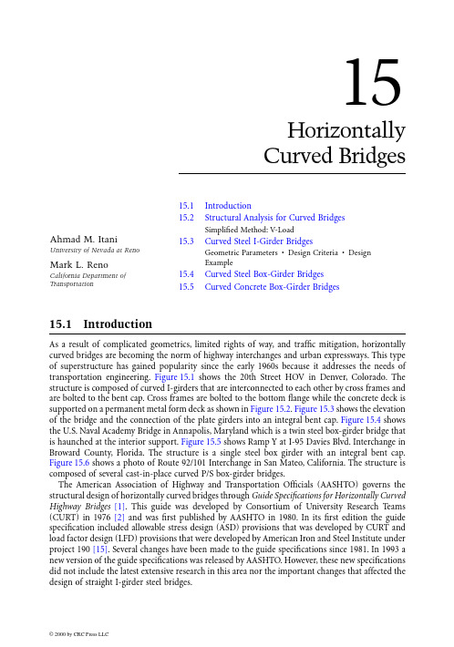
15HorizontallyCurved Bridges15.1 Introduction15.2 Structural Analysis for Curved BridgesSimplified Method: V-Load15.3 Curved Steel I-Girder Bridges Geometric Parameters •Design Criteria •DesignExample 15.4 Curved Steel Box-Girder Bridges 15.5 Curved Concrete Box-Girder BridgesAs a result of complicated geometrics, limited rights of way, and traffic mitigation, horizontally curved bridges are becoming the norm of highway interchanges and urban expressways. This type of superstructure has gained popularity since the early 1960s because it addresses the needs of transportation engineering. Figure 15.1 shows the 20th Street HOV in Denver, Colorado. The structure is composed of curved I-girders that are interconnected to each other by cross frames and are bolted to the bent cap. Cross frames are bolted to the bottom flange while the concrete deck is supported on a permanent metal form deck as shown in Figure 15.2. Figure 15.3 shows the elevation of the bridge and the connection of the plate girders into an integral bent cap. Figure 15.4 shows the U.S. Naval Academy Bridge in Annapolis, Maryland which is a twin steel box-girder bridge that is haunched at the interior support. Figure 15.5 shows Ramp Y at I-95 Davies Blvd. Interchange in Broward County, Florida. The structure is a single steel box girder with an integral bent cap.Figure 15.6 shows a photo of Route 92/101 Interchange in San Mateo, California. The structure is composed of several cast-in-place curved P/S box-girder bridges.The American Association of Highway and Transportation Officials (AASHTO) governs the structural design of horizontally curved bridges through Guide Specifications for Horizontally Curved Highway Bridges [1]. This guide was developed by Consortium of University Research Teams (CURT) in 1976 [2] and was first published by AASHTO in 1980. In its first edition the guide specification included allowable stress design (ASD) provisions that was developed by CURT and load factor design (LFD) provisions that were developed by American Iron and Steel Institute under project 190 [15]. Several changes have been made to the guide specifications since 1981. In 1993 a new version of the guide specifications was released by AASHTO. However, these new specifications did not include the latest extensive research in this area nor the important changes that affected the design of straight I-girder steel bridges.Ahmad M. ItaniUniversity of Nevada at Reno Mark L. RenoCalifornia Department ofTransportationFIGURE 15.1Curved I-girder bridge under construction — 20th St. HOV, Denver, Colorado.FIGURE 15.2Bottom view of curved I-girder bridge.The guide specifications for horizontally curved bridges under Project 12-38 of the National Cooperative Highway Research Program (NCHRP) [3] have been modified to reflect the current state-of-the-art knowledge. The findings of this project are fully documented in NCHRP interim reports: “I Girder Curvature Study” and “Curved Girder Design and Construction, Current Practice”[3]. The new “Guide Specifications for Horizontally Curved Steel Girder Highway Bridges” [18]proposed by Hall and Yeo was adopted as AASHTO Guide specifications in May, 1999. In addition to these significant changes, the Federal Highway Administration (FHWA) sponsored extensive theoretical and experimental research programs on curved girder bridges. It is anticipated that these programs will further improve the current curved girder specifications. Currently, the NCHRP 12–50 is developing “LRFD Specifications for Horizontally Curved Steel Girder Bridges” [19].The guidelines of curved bridges are mainly geared toward structural steel bridges. Limited information can be found in the literature regarding the structural design of curved structural concrete (R/C and P/S) bridges. Curved structural concrete bridges have a box shape, which makes the torsional stiffness very high and thus reduces the effect of curvature on the structural design.The objective of this chapter is to present guidelines for the design of curved highway bridges.Structural design of steel I-girder, steel, and P/S box-girder bridges is the main thrust of this chapter.The accuracy of structural analysis depends on the analysis method selected. The main purpose of structural analysis is to determine the member actions due to applied loads. In order to achieve reliable structural analysis, the following items should be properly considered:•Mathematical model and boundary conditions•Application of loadsFIGURE 15.3Curved I-girder bridge with integral bent cap.FIGURE 15.4Twin box-girder bridge — U.S. Naval Academy Bridge, Annapolis, Maryland.FIGURE 15.5Single box girder bridge with integral bent cap — Ramp Y, I-95 Davies Blvd., Broward County, Florida.The mathematical model should reflect the structural stiffness properly. The deck of the super-structure should be modeled in such a way that is represented as a beam in a grid system or as a continuum. The boundary conditions in the mathematical model must be represented teral bearing restraint is one of the most important conditions in curved bridges because it affects the design of the superstructure. The deck overhang, which carries a rail, provides a significant torsion resistance. Moreover, the curved bottom flange would participate in resisting vertical load.This participation increases the applied stresses beyond those determined by using simple structural mechanics procedures [3].Due to geometric complexities, the gravity load will induce torsional shear stresses, warping normal stresses, and flexural stresses to the structural components of horizontally curved bridges.To determine these stresses, special analysis accounting for torsion is required. Various methods were developed for the analysis of horizontally curved bridges, which include simplified and refined analysis methods. The simplified methods such as the V-Load method [4] for I-girders and the M/R method for box girders are normally used with “regular” curved bridges. However, refined analysis will be required whenever the curved bridges include skews and lateral or rotational restraint. Most refined methods are forms of finite-element analysis. Grillage analysis as well as three-dimensional (3-D) models have been used successfully to analyze curved bridges. The grillage method assumes that the member can be represented in a series of beam elements. Loads are normally applied through a combination of vertical and torsion loads. The 3-D models that represent the actual depth of the superstructure will capture the torsion responses by combining the responses of several bridge elements.15.2.1Simplified Method: V-LoadIn 1984, AISC Marketing, Inc. published “V-Load Analysis” for curved steel bridges [4]. This report presented an approximate simplified analysis method to determine moments and shears for horizontally FIGURE 15.6Curved concrete box-girder bridges — Route 92/101 Interchange, San Mateo, California.curved open-framed highway bridges. This method is known as the V-Load method because a large part of the torsion load on the girders is approximated by sets of vertical shears known as “V-Loads.”The V-Load method is a two-step process. First, the bridge is straightened out so that the applied vertical load is assumed to induce only flexural stresses. Second, additional fictitious forces are applied to result in final stresses similar to the ones in a curved bridge. The additional fictitious forces are determined so that they result in no net vertical, longitudinal, or transverse forces on the bridge.Figure 15.7 shows two prismatic girders continuous over one interior support with two equal spans, L 1. Girder 1 has a radius of R and the distance between the girders is D . The cross frames are uniformly spaced at distance equal to d . As shown later, the cross frames in curved bridges are primary members since they are required to resist the radial forces applied on the girder due to bridge curvature.When the gravity load is applied, the flanges of the plate girder will be subjected to axial forces F = M/R, as shown in Figure 15.8. However, due to the curvature of the girder, laterally distributed load q will be applied to flanges of the plate girder in order to achieve equilibrium. By assuming that the flanges resist most of the bending moment, the longitudinal forces in the flanges at any point will be equal to the moment, M , divided by the section height, h . Due to the curvature of the bridge, these forces are not collinear along any given segment of the flange. Thus, radial forces must be developed along the girder in order to maintain equilibrium. The forces cause lateral bending FIGURE 15.7Plan view of two-span curved bridge.FIGURE 15.8Plan view of curved bridge top flange.of the girder flanges resulting in warping stresses. The magnitude of the radial forces is equal to M/hR and has the same shape of the bending moment diagram as shown in Figure 15.9.This distributed load creates equal and opposite reaction forces at every cross frame as shown in Figure 15.10. By assuming the spacing between the cross frames is equal to d , the reaction force at the cross frame is equal to H , which is equal to Md/hR .To maintain equilibrium of the cross frame forces, vertical shear forces must develop at the end of the cross frames as a result of cross frame rigidity and end fixity as shown in Figure 15.11.15.3.1Geometric ParametersAccording to the current AASHTO specifications [13], the effect of curvature may be neglected in determining the primary bending moment in longitudinal members when the central angle of each span in a two or more span bridge is less than 5° for five longitudinal girders. The framing system FIGURE 15.9Lateral forces on curved girder flange.FIGURE 15.10Reaction at cross frame location.for curved I-girder bridges may follow the preliminary design of straight bridges in terms of span arrangement, girder spacing, girder depth, and cross frame types. The choice of the exterior span length is normally set to give relatively equal positive dead-load moments in the exterior and interior spans. The arrangement results in the largest possible negative moment, which reduces both positive moments and related deflections. Normally, the depth of the superstructure is the same for all spans.Previous successful design showed a depth-to-span ratio equal to 25 for the exterior girder to be adequate. This ratio has been based on vibration and stiffness needed to construct the plate girders.Also, this ratio helps to ensure that the girders do not experience excessive vertical deflections. The uplift of the exterior girder should be prevented as much by extending the span length of the exterior girder rather than dealing with the use of tie-down devices.Girder spacing plays a significant role in the deck design and the determination of the number of girders. Wider spacing tends to increase the dead load on the girders, while closer spacing requires additional girders, which increases the fabrication and erections costs. For curved steel I-girder bridges, the girder spacing varies between 3.05 m (10 ft) and 4.87 m (16 ft). Wider spacing, common in Europe and Japan, requires a post-tensioned concrete deck, which is not common practice in the United States. The overhang length should not exceed 1.22 m (4 ft) because it tends to increase the load on the exterior girders by adding more dead load and permitting truckload to be applied on the cantilever. The flanges of the plate girder should have a minimum width to avoid out-of-plane buckling during construction. Many steel erectors limit the length of girder shipping pieces to 85 times the flange width [5]. Based on that, many bridge engineers tend to limit the width of the flange to 40.6 mm (16 in) based on a maximum shipping length equal to 36.6 m (120 ft). It is also recommended that the minimum web thickness be limited to 11.1 mm (⁷⁄₁₆ in) because of weld distortion problems. The thickness of the web depends on its depth and the spacing of the transverse stiffeners. This represents a trade-off between having extra material or adding more stiffeners. Many bridge engineers use the ratio of D/t =150 to choose the thickness of the web.The spacing of the cross frame plays an important factor in the amount of force carried out by it and the value of flange lateral bending. Normally, cross-frame spacing is held between 4.57 m (15 ft) and 7.62 m (25 ft).15.3.2Design CriteriaThe design guidelines, according to the Recommended Specifications for Steel Curved Girder Bridges [3], are established based on the following principles:•Statics•StabilityFIGURE 15.11Equilibrium at cross frame location and the formation of V-loads.•Strength of materials•Inelastic behaviorExternal and internal static equilibrium should be maintained under every expected loading condition. Stability of curved steel girder bridges is a very important issue especially during con-struction. By their nature, curved girders experience lateral deflection when subjected to gravity loading. Therefore, these girders should be braced at specified intervals to prevent lateral torsional buckling. The compactness ratio of the web and the flanges of curved I-girders are similar to the straight girders. The linear strain distribution is normally assumed in the design of curved girder bridges. The design specification recognizes that compact steel sections can undergo inelastic defor-mations; however, current U.S. practice does not utilize a compact steel section in the design of curved I-girder bridges.The design criteria for curved girder bridges can be divided into two main sections.•Strength•ServiceabilityLimit state design procedures are normally used for the strength design, which includes flexure and shear. Service load design procedures are used for fatigue design and deflection control. The primary members should be designed to be such that their applied stress ranges are below the allowable fatigue stress ranges according to AASHTO fatigue provisions [6]. The deflection check is used to ensure the serviceability of the bridge. According to the recommended specifications for the design of curved steel bridges [3], the superstructure should be first analyzed to determine the first mode of flexural vibration. The frequency of this mode is used to check the allowable deflection of the bridge as indicated in the Ontario Bridge Code[7].15.3.3Design ExampleFollowing the 1994 Northridge Earthquake in California, the California Department of Transpor-tation (Caltrans) embarked on a task of rebuilding damaged freeways as soon as possible. At the SR 14–I-5 interchange in the San Fernando Valley, several spans of cast-in-place prestressed concrete box girders have collapsed [9]. These were the same ramps that were previously damaged during the 1971 San Fernando Earthquake [8]. Because of the urgency of completion and the restrictions on geometry, steel plate girders were considered a viable replacement alternative. The idea was that the girders could be fabricated while the substructure was being constructed. Once the footings and columns were completed, the finished girders would be delivered to the job site. Therefore, in a period of 5 weeks Caltrans designed two different alternatives for two ramps approximately 396 m (1300 ft) and 457 m (1500 ft) in length. The South Connector Ramp will be discussed in this section. The “As-Built” South Connector was approximately 397 m (1302 ft) in length set on a horizontal curve with a radius of 198 m (650 ft) producing a superelevation of 11%. This ramp was designed utilizing Bridge Software Development International (BSDI) curved girder software package [10] as one frame with expansion joints at the abutments. This computer program is considered one of the most-advanced programs for the analysis and design of curved girder bridges. The program analyses the curved girders based on 3-D finite-element analysis and utilizes the influence surface for live-load analysis. The program has also an interactive postprocessor for performing designs and code checking. The design part of the program follows the 15th edition of AASHTO [13] and the Curved Girder Guide Specifications [1]. The ramp was then checked using DESCUS I [14], another software package, and spot-checked with in-house programs developed by Caltrans. A cross-sectional width of 11.43 m (37.5 ft) was selected for two lanes of traffic (3.66 m, 12 ft), two shoulders (1.52 m, 5 ft), and two concrete barriers (0.533 m, 1.75 ft). This ramp has a 212.7 mm (8⅜ inch) concrete deck, which was composite with four continuous welded plate girders with bolted field splices for erection. The material selected was A709 Grade 50W. The spans ranged from35.97 m (118 ft) up to 66.44 m (218 ft) in length, which meant the girder depths alone were around 2.2 m (7.25 ft) deep and the composite section was 2.44 m (8 ft) deep. The cross frames were a mixture of inverted K frames and plate diaphragms at the bents. The K frames were inverted so as to place the catwalks between the girders, and the braces were changed to plate sections at the bents to help handle the large seismic forces that are transmitted from the superstructure to the “ham-merhead” bent caps both longitudinally and transversely. The bracing was designed for both live-load and seismic-load conditions. Figure 15.12 shows the elevation of intermediate cross frames. The bracing was held to a spacing of less than 6.1 m (20 ft).The BSDI program works by placing unit loads on a defined geometry pattern of the deck. Then an influence surface is developed so that application of loads for maximum and minimum stresses becomes a simple numerical solution. This program was thoroughly checked utilizing the V-Load method and using an SC-Bridge package that utilizes GT Strudl [11] for the moving load generator. Good correlation was seen by all methods with the exception of the V-Load, which consistently gave more conservative results. As is frequently the case with curved girders, the outside girder ends up being designed heavier than the remaining sections. This difference can be as little as 15%, but as great at 40%, depending on location. It should also be understood that by designing a stiffer girder for the outside, there is the tendency to attract more loads, thereby requiring more material. This is a similar phenomenon to that seen in seismic design. The BSDI system allows the designer to check for construction loads and sequencing. This was absolutely critical on a project like this as the girder sections were often controlled by the sequence of construction load application. Limits on concrete pours were set around limiting stresses on the girders.Girder plate sizes were optimized both for the design and for the fabrication. A typical span would have five different sections in it. There were two sections at either end over the bents. The top and bottom flanges were very similar at point of maximum negative moment. Then on either side a transition section would be utilized until the inflection point. Finally, a maximum positive section where there is usually a significant difference in the top and bottom flanges was designed. The elevation of the plate girder that shows the different flange dimensions is shown in Figure 15.13. The five different flange dimensions were justified by considering the material costs vs. the welded splice costs. In addition, the “transition” sections were often sized such that the top flange width was the same as the negative moment sections. This way the plates could be welded end to end and then all four girders could be cut on one bed with one operation, saving handling costs. Plate sections were also set based on erection and shipping capabilities.Steel was a good choice of structure type for this project because of the seismic risk, which exists in this location. Several faults pass in the vicinity of this interchange, and the structure would be subjected to “near-fault” phenomenon. This structure was designed with vertical acceleration. The plate girder with concrete deck superstructure weighs one third as much as the traditional cast-in-place box structure. Some ductile steel details were developed for this project [12]. Since the girders rest on a hammerhead bent cap, the load transfer mechanism is through the bearings and the shear can be as much as the plastic shear of the column. To make this load transfer possible, plate diaphragms were designed at the bent caps. With the plates in place, a concrete diaphragm could be poured that would not only add stiffness, but strength to handle these large seismic forces. The diaphragms were approximately 0.91 m (3 ft) wide by the depth of the girder. The plates were covered with shear studs and reinforcing was placed prior to the concrete. In addition, pipe shear keys were installed in the top of the bent cap on either side of the diaphragm. This structure was redundant in that if the displacements were excessive, the pipes would be engaged.FIGURE 15.12Elevation of intermediate cross frames.FIGURE 15.13Elevation of interior and exterior curved plate girder.The most common type of curved steel box girder bridges are tub girders that consist of independent top flanges and cast-in-place reinforced concrete decks. The design guidelines are covered in the “Recommended Specifications for Steel Curved Girder Bridges”[3]. Normally the tub girder is composed of a bottom plate flange, two web plates, and an independent top flange attached to each web. The top flanges should be braced to become capable of resisting loads until the girder acts in a composite manner. The tub girders require internal bracing because of the distortion of the box due to the bending stresses. Finite-element analysis, which accounts for the distortion, is normally utilized to calculate the stresses and displacement of the box.The webs of the box girder may be inclined with a ratio of one-to-four, width-to-depth. The AASHTO provisions for straight box girders apply for curved boxes regarding the shear capacity of the web and the ultimate capacity of the tub girders. The maximum bending stresses are determined according to the factored loads with the considerations of composite and noncomposite actions. Bending stresses should be checked at critical sections during erection and deck placement. The bending stresses may be assumed uniform across the width of the box. Prior to curing of concrete, the top flanges of tub girders are to be assumed laterally supported at top flange lateral bracing. The longitudinal warping stresses in the bottom flange are computed based on the stiffness and spacing of internal bracing. It is recommended that the warping stresses should not exceed 15% of the maximum bending stresses.As mentioned earlier, the M/R method is usually used to analyze curved box girder bridges. The basic concept behind this method is the conjugate beam analogy. The method loads a conjugate simple span beam with a distributed loading, which is equal to the moment in the real simple or continuous span induced by the applied load divided by the radius of curvature of the girder. The reactions of the supports are obtained and thus the shear diagram can be constructed representing the internal torque diagram of the curved girder. After the concentrated torque at the ends of the floor beam is known, the end shears are computed from statics. These shears are applied as vertical concentrated loads at each cross frame location to determine the moment of the developed girder. This procedure constitutes a convergence process whereby the M/R values are applied until conver-gence is attained.Current curved bridge specifications in the United States do not have any guidelines regarding curved concrete box-girder bridges. It is generally believed that the concrete monolithic box girders have high torsional rigidity, which significantly reduces the effect of curvature. However, during the last 15 years a problem has occurred with small-radius horizontally curved, post-tensioned box-girder bridges. The problem has occurred at two known sites during the construction [16]. The problem can be summarized as, during the prestressing of tendons in a curved box girder, they break away from the web tearing all the reinforcement in the web along the profile of the tendon. Immediate inspection of the failure indicated that the tendons exerted radial horizontal pressure along the wall of the outermost web.In recognition of this problem, Caltrans has prepared and implemented design guidelines since the early 1980s [17]. Charts and reinforcement details were developed to check girder webs for containment of tendons and adequate stirrup reinforcement to resist flexural bending. Caltrans’Memo-to-Designers 11-31 specifies that designers of curved post-tensioned bridges should consider the lateral prestress force, F, for each girder. This force F is equal to the jacking force, P j, of each girder divided by the horizontal radius of the girder. If the ratio of P j/R > 100 kN/m per girder orthe horizontal radius is equal to 250 m or less, Detail A, as shown in Figure 15.14 should be used.Charts for No. 16 and No. 19 stirrups were developed to be used with the ratio of P j /R in order to get minimum web thickness and spacing between the No. 16 stirrups, as shown in Figure 15.15.The first step is to enter the chart with the value of F on the vertical axis of the chart and travel horizontally until the height of the web h c is reached. The chart then indicates the minimum web thickness and the spacing of the No. 16 stirrups.These charts were developed assuming that the girder web is a beam with a length equal to the clear distance between top and bottom slabs. The lateral force, F , is acting at the center point of the web creating a bending moment in the web. This moment is calculated by the simple beam formula reduced by 20% for continuity between the web and slabs. The value of this bending moment is equal to(15.1)In the commentary of this memo, Caltrans considered the stirrups to be capable of handling the bending and shear stresses for the following reasons:•M u is calculated for the maximum conditions of F acting at h c /2. This occurs at only two points in a span due to tendon drape.•The jacking force, P j , is used in the calculation of M u and, at the time P j is applied, the structure is supported on falsework. When the falsework is removed and vertical shear forces act, the prestressing forces will be reduced by the losses.In addition, for curve box girders with an inside radius of under 243.8 m (800 ft), intermediate diaphragms are required at a maximum spacing of 24.4 m (80 ft) unless shown otherwise by tests or structural analysis. The code goes further to say that if the inside radius is less than 121.9 m (400ft), the diaphragm spacing must not exceed 12.2 m (40 ft).FIGURE 15.14Caltrans duct detail in curved concrete bridges.The authors would like to thank Dr. Duan and Prof. Chen for selecting them to participate in this Bridge Engineering Handbook . The National Steel Bridge provided the photographs of curved bridges in this document for which the authors are sincerely grateful. The support and the cooperation of Mr. Dan Hall of BSDI are appreciated. Finally, the two authors warmly appreciate the continued support of Caltrans.References1.AASHTO, Guide Specifications for Horizontally Curved Highway Bridges , American Association ofState Highway and Transportation Officials, Washington, D.C., 1993, 1–111.FIGURE 15.15Caltrans chart design for web thickness and reinforcement.2.Mozar, J., Cook, J., and Culver, C., Horizontally Curved Highway Bridges-Stability of Curved PlateGirders, Report No. P1, Carnegie-Mellon University, CURT Program, Pittsburgh, PA, Sept. 1971.3.Hall, D. H. and Y oo, C. H., Curved Girder Design and Construction, Current Practice, NCHRPProject 12-38, 1995, 1–136.4.V-Load analysis, in USS Highway Structures Design Handbook, Vol. 1, AISC Marketing, Inc., Chi-cago, IL, 1984, chap. 12, 1–565.AISC, Highway Structure Design Handbook, Newsletter Issue No. 2, AISC Marketing, Chicago, IL,19916.AASHTO, LRFD Bridge Design Specifications, American Association of State Highway and Trans-portation Officials, Washington, D.C, 1994.7.Ontario Highway Bridge Design Code, 3rd ed., Ministry of Transportation and Communications,Highway Engineering Division, Toronto, Ontario, 1991.8.The San Fernando Earthquake — Field Investigation of Bridge Damage, State of California, Cal-trans, Division of Structures, Sacramento, 1991.9.Northridge Earthquake — Field Investigation of Bridge Damage, State of California, Caltrans,Division of Structures, Sacramento, 1994.10.Hall, D. H., BSDI 3D System, Internal Document, Bridge Software Development International,Ltd., Coopersburg, PA, 1994.11.SC-Bridge, User’s Guide, Version 2.1, SC Solutions, Mountain View, CA, 1994.12.Itani, A. and Reno, M., Seismic design of modern steel highway connectors, in ASCE StructuresCongress, Vol. 2, 1995, 1528–1531.13.AASHTO, Standard Specifications for Highway Bridges, 15th ed. with interim’s, American Associa-tion of State Highway and Transportation Officials, Washington, D.C., 1994.14.DESCUS I and II, Opti-Mate, Inc., Bethlehem, PA.15.Analysis and Design of Horizontally Curved Steel Bridges, U.S. Steel Structural Report ADUCO91063, May 1963.16.Podolny, W., The cause of cracking in post-tensioned concrete box girder bridges and retrofitprocedures, PCI J., March 1985.17.Caltrans, Bridge Memo-to-Designers, Vol. 1, California Department of Transportation, Sacra-mento, 1996.18.Hall, D.H. and Y oo, C.H., Recommended Specifications for Steel Curved-Girder Bridges, NCHRPProject 12–38. BSDI, Ltd., Coopersburg, PA, Dec. 1998.19.NCHRP (12–52), LRFD Specifications for Horizontally Curved Steel Girder Bridges, Transporta-tion Research Board, Washington, D.C.。
Construction, engineering and Design
2Construction, engineering and DesignT he construction industry, a mainstay ofthe Chine se e conomy, has unde rg oneunprecedented growth in recent years.Ongoing infrastructure development, driven by the2008 Olympics in Beijing and the 2010 World Expoin Shanghai, will continue to play a significant rolein raising the quality level and expanding the useof innovative contractual and financial models toimprove the standard and efficiency of constructionactivity in China.Significant DevelopmentsIn the past year, the Ministry of Construction (MOC)has issued the following rules and regulationsgoverning the operations of foreign construction,engineering and design companies: RegulationsGoverning the Management of Qualifications forConstruction Supervision Enterprises (Decree158) and its Implementation Rules (Circular 190);the Regulations Governing the Management ofQualifications for Construction Enterprises (Decree159) and its Implementation Rules (Circular 241);and the Regulations Governing the Management ofQualifications for Construction Survey and DesignEnterprises (Decree 160) and its ImplementationRules (Circular 202).The much anticipated Regulation Governing theManagement of Foreign-invested EngineeringServices Enterprises (Decree 155), which wasdirected at foreign-invested construction, tendering,supervision and cost advisory enterprises, was issuedin March 2007. The MOC and its local counterpartshave not begun accepting applications submittedunder Decree 155 and are not expected to do so untilthe Implementation Rules for Decree 155 are issued.The MOC also issued the Qualification Standards forEngineering Design (Circular 86) in March 2007,which superseded Circular 22. Companies applyingfor design qualifications under Decrees 114 and 160must be sure to comply with Circular 86 as well.Unlike Decrees 113, 114 and 155, which apply only toforeign-invested enterprises (FIEs), Decrees 158, 159and 160 and their corresponding ImplementationRules apply to both domestic and foreign-investedconstruction supervision enterprises, constructionenterprises, construction survey enterprises anddesign enterprises. Therefore, FIEs must complywith both sets of regulations (e.g., Foreign-InvestedDesign Enterprises (FIDEs) must comply withDecrees 114 and 160 and Circulars 86 and 202).Specific IssuesConstruction Works Sector – Decree 113Decree 113 delineates the necessary qualifications andrequirements that foreign construction companiesmust have before they can undertake constructionactivities in China. Specifically, a foreign constructioncompany must establish a local presence by settingup some form of Chinese legal entity (either awholly foreign-owned enterprise (WFOE) or a Sino-foreign joint venture). After its establishment, thisChinese legal entity must apply for the appropriateconstruction grade qualification so that it becomes aForeign-Invested Construction Enterprise (FICEs).Separate Qualification StandardsThe grade qualification determines the maximumsize and scale of projects that a constructionenterprise may undertake. In March 2007, the MOCissued the Qualification Standards for Special ClassMain Contractors (Circular 72), which updatedthe Qualification Standards for Special Class MainContractors. Circular 72 divided the universalqualification standards for construction enterprisesthat were put forth in Circular 82 by the MOC inApril 2001. This divided system, in which Circular72 applies to Special Class Main Contractors andCircular 82 applies to all other grades of maincontractors as well as all specialty contractors andlabor sub-contractors, will remain in existence untilthe MOC updates the rest of Circular 82 to make itconsistent with Circular 72. AmCham urges the MOCto integrate the system and clarify the situationbefore the transition period ends.The concerns mentioned in previous White Papersregarding the upgrading of qualifications were easedsomewhat by Circular 241, which provides that thereis no time limit preventing construction enterprisesfrom applying for an upgrade. While AmCham ispleased that design companies with several general2建筑、工程和设计建筑、工程和设计作为中国经济的支柱产业之一,建筑业近年来经历了前所未有的增长。
土木工程专业(交通土建)课程简介汇总
道路桥梁与渡河工程《理论力学A》课程简介课程编号:090213201中文名称:理论力学A英文名称:Theory Mechanics A学分学时:5.0-80开课学期:秋季先修课程:《材料力学》、《工程地质》、《弹性力学》、《水力学》适应专业:土木工程及水利工程类课程类别:本专业大类课程课程性质:必修考核形式:考试教材:《理论力学》哈尔滨工业大学理论力学教研室主编高等教育出版社主要参考书:1《静力学》谢传峰主编高等教育出版社《动力学》谢传峰主编高等教育出版社.内容简介:《理论力学》分为I II 两册。
I册包括静力学(静力学公理、物体的受理分析、平面力系、空间力系、摩擦),运动学(点的运动学、刚体的简单运动、点的合成运动、刚体的平面运动等)和动力学(质点的动力学基本方程、动量定理、动量矩定力、动能定理、达朗贝尔原理、虚位移原理等)。
II册包括分析力学基础、非惯性系中的质点动力学、碰撞、机械振动基础、刚体定点运动、自由刚体运动、刚体运动的合成、变质量动力学等。
《材料力学A》课程简介课程编号:090213204中文名称:材料力学A英文名称:Materiol Mechanics A学分学时:4.5-72开课学期:春季课程类别:本专业大类课程课程性质:必修考核形式:考试教材:《材料力学I》刘鸿文主编高等教育出版社主要参考书:《材料力学学习指导书》内容简介:本教材第一册包含了材料力学课程中的基本内容,内容包括:绪论,拉伸,压缩与剪切,扭转,弯曲内力,弯曲应力,弯曲变形,应力和应变分析,强度理论,组合变形,压杆稳定,动载荷,交变应力,平面图形的几何性质等。
第二册包含了材料力学课程较深入的内容,内容包括:弯曲的几个补充问题,能量方法,超静定结构,平面曲杆,厚壁圆桶和旋转圆盘,矩阵位移发,杆件的塑性变形等。
《工程测量A》课程简介课程编号:060313004中文名称:《工程测量A》英文名称:Engineering SurveyA学分学时:3.5-56开课学期:春季课程类别:本专业大类课程课程性质:必修考核形式:考试教材:《测量学》许娅娅应主编人民交通出版社内容简介:本课程介绍了测量学的基本概念与理论,阐述了测量学的基本知识和测量仪器(包括常规和新型仪器)的使用方法,介绍了测量误差的基本知识,小区域控制测量,包括平面控制测量和高程控制测量的施测与计算,大比例尺地图测绘的传统方法和数字化测图方法,大比例尺地形图应用及数字地面模型在公路工程中的应用,施工测量的基本工作,道路中线测量、纵横断面测量,桥梁测量、隧道测量,“3S”技术及其应用。
非赫兹接触下轮轨接触蠕滑力的计算
第29卷第4期铁 道 学 报Vol.29 No.42007年8月J OURNAL OF T H E CHINA RA IL WA Y SOCIET Y August 2007文章编号:100128360(2007)0420096205非赫兹接触下轮轨接触蠕滑力的计算王小松1,2, 葛耀君2, 吴定俊2(1.重庆交通大学桥梁系,重庆 400074;2.同济大学土木工程防灾国家重点实验室,上海 200092)摘 要:以弹性半空间非赫兹接触理论计算轮轨法向接触问题,得到比较真实的法向压力分布。
在此基础上,根据修正的FastSim 算法计算了轮轨在单点接触、轮缘接触和单接触斑内两点接触情况下的蠕滑力。
与CON 2TACT 的对比表明,修正的FastSim 算法在计算轮缘接触时具有比较精确的结果,在计算单接触斑内两点接触时的精度相对于Shen 2Hedrick 2Elkins 理论和FastSim 算法均有较大的提高。
基于修正的FastSim 算法编制了便于风2列车2桥梁耦合分析应用的蠕滑力插值数表MFT TL M 。
关键词:非赫兹接触;轮轨接触;蠕滑力中图分类号:U211.5 文献标志码:AC alculation of Creep Forces of Wheel 2rail Contact under Non 2H ertzian ConditionsWAN G Xiao 2song 1,2, GE Yao 2jun 2, WU Ding 2jun 2(1.Depart ment of Bridge Engineering ,Chongqing Jiaotong University ,Chongqing 400074,China ;2.State Key Laboratory for Disaster Reduction in Civil Engineering ,Tongji University ,Shanghai 200092,China )Abstract :Based on t he real normal p ressure dist ribution of wheel 2rail contact ,which is obtained by t he elastic half 2space non 2Hertzian co ntact t heory ,t he Fast Sim algorit hm is modified and t hen applied to calculate t he creep forces under t he circumstances of single contact ,flange contact and double contact in t he single contact parison wit h CON TACT indicates t hat t he modified Fast Sim algorit hm gives relatively accurate re 2sult s when flange co ntact occurs ,and compariso n wit h t he Fast Sim algorit hm and Shen 2Hedrick 2Elkins t heory shows t hat t he modified Fast Sim algorit hm gives better solution when double contact occurs in t he single con 2tact zone.The modified Fast Sim Traction Table used for wind 2vehicle 2bridge coupling analysis is also compiled.K ey w ords :non 2Hertzian contact ;rail 2wheel contact ;creep force 轮轨接触蠕滑力的计算是风2列车2桥梁耦合振动分析中的核心问题之一。
p c ching 程伯中
P. C. Ching 程伯中Publications in International Journals and Conference Proceedings :A. Refereed Journal Publications1.Feng Tian, Xiang-Gen Xia, P.C. Ching, Wing-Kin Ma, “Signal Detection in a Space-Frequency Coded Cooperative Communication System with Multiple Carrier Frequency Offsets by Exploiting Specific Properties of the Code Structure”, IEEE Transactions on Vehicular Technology, Volume 58, No. 7, September 2009, pp 3396-34092.Wei Zhang, Yabo Li, Xiang-Gen Xia, P.C. Ching, Khaled Ben Letaief, “DistributedSpace-Frequency Coding for Cooperative Diversity in Broadband Wireless Ad HocNetworks”, IEEE Transactions on Wireless Communications, Volume 7, Issue 3,March 2008, pp. 995-10033.Nengheng Zheng, Tan Lee, Ning Wang, P.C. Ching, “Integrating ComplementaryFeatures from Vocal Source and Vocal Tract for Speaker Identification”, International Journal of Computational Linguistics & Chinese Language Processing, Volume 12, No.3, September 2007, pp. 273-2904.Wei Zhang, Xiang-Gen Xia, Ching, P.C., “Full-Diversity and Fast ML DecodingProperties of General Orthogonal Space-Time Block Codes for MIMO-OFDMSystems”, IEEE Transactions on Wireless Communications, Volume 6, Issue 5, May 2007, pp. 647-6535.Nengheng Zheng; Tan Lee, P.C. Ching, “Integration of Complementary AcousticFeatures for Speaker Recognition”, IEEE Signal Processing Letters, Volume 14, Issue 3, March 2007, pp. 181-1846.Shan Ouyang, Tan Lee, P.C. Ching, “A power-based adaptive method for eigenanalysiswithout square-root operations”, Digital Signal Processing, Volume 17, Issue 1, January 2007, pp. 209-2247.Zhang, W., Xia, X.G., Ching, P. C., “High-Rate Full-Diversity Space–Time–Frequency Codes for Broadband MIMO Block-Fading Channels”, IEEE Transactions on Communications, Volume 55, Issue 1, Jan. 2007, pp. 25-348.Wei Zhang; Xiang-Gen Xia; P.C. Ching, “Clustered pilot tones for carrier frequencyoffset estimation in OFDM systems”, IEEE Transactions on Wireless Communications, Volume 6, Issue 1, Jan. 2007, pp 101-1099.Zhang, W., Xia, X. G., Ching, P. C., “Optimal Training and Pilot Pattern Design forOFDM Systems in Rayleigh Fading”, IEEE Transactions on Broadcasting, Volume 52, Issue 4, Dec. 2006, pp. 505-51410.Meng Yuan, Tan Lee, P.C. Ching, Yu Zhu, “Speech recognition on DSP: issues oncomputational efficiency and performance analysis”, Microprocessors andMicrosystems. Vol. 30, Issue 3, May 2006, pp 155-16411.Yiu-Tong Chan, Herman Yau, P.C. Ching, “Exact and Approximate MaximumLikelihood Localization Algorithms”, IEEE Trans. on Vehicular Technology, Vol. 55, No. 1, Jan. 2006, pp 10-1612.Yiu-Tong Chan, Wing-Yue Tsui, Hing-Cheung So, P.C. Ching, “Time-of-Arrival BasedLocalization under NLOS Conditions”, IEEE Trans. on Vehicular Technology, Vol. 55, No. 1, Jan. 2006, pp 17-2413.Hong Zhang, Xiang-Gen Xia, Leonard Cimini, Jr., P.C. Ching, “SynchronizationTechniques and Guard-Band Configuration Scheme for Single-Antenna Vector-OFDMSystems”, IEEE Trans. on Wireless Communications, Vol. 4, No. 5, September 2005, pp 2454-246414.W.K. Ma, P.C. Ching, Ba Ngu Vo, “Crosstalk Resilient Interference Cancellation inMicrophone Arrays Using Capon Beamforming”, IEEE Trans. on Speech and Audio Processing, Vol. 12, No. 5, September 2004, pp. 468-47715.H.C. So, P.C. Ching, “Adaptive algorithm for direct frequency estimation”, IEEProceedings – Radar, Sonar and Navigation, Vol. 151, No. 6, December 2004, pp. 359-36416.W.K. Ma, P.C. Ching, Zhi Ding, “Semidefinite Relaxation Based Multiuser Detectionfor M-ary PSK Multiuser Systems”, IEEE Trans. on Signal Processing, Vol. 52, No.10, October 2004, pp. 2862-287217.W.K. Ma, Timothy N. Davidson, Kon Max Wong, P.C. Ching, “A Block AlternatingLikelihood Maximization Approach to Multiuser Detection”, IEEE Trans. on SignalProcessing, Vol. 52, No. 9, September 2004, pp. 2600-261118.W. K. Lo, Helen M. Meng, P.C. Ching, “Multi-Scale Document Retrieval for CantoneseBroadcast News”, International Journal of Speech Technology, Vol. 7, 2004, pp. 203-21919.Lee Tan, Helen M. Meng, W.K. Lo, P.C. Ching, “The State-of-the-Art in Human-computer Speech-based Interface Technologies”, The HKIE Transactions, Vol. 10, No.4, October 2003, pp. 50-6120.Y. Wu, H.C. So, P.C. Ching, “Joint Time Delay and Frequency Estimation via State-Space Realization”, IEEE Signal Processing Letters, Vol. 10, No. 11, November 2003, pp 339-34221.W.K. Ma, P.C. Ching, “Asymptotic Minimum Bit Error Rate Property of Maximum-Likelihood Multiuser Detection”, IEEE Communications Letters, Vol. 7, No. 9,September 2003, pp. 425-42722.W.K. Lo, Helen Meng, P.C. Ching, “Cross-Language Spoken Document RetrievalUsing HMM-based Retrieval Model with Multi-Scale Fusion”, ACM Transactions on Asian Language Information Processing, Vol. 2, No. 1, March 2003, pp. 1-26"23.Shan Ouyang, P.C. Ching, Tan Lee, “Quasi-Newton algorithm for adaptive minorcomponent extraction”, Electronics Letters, 12th September 2002, vol. 38, No. 19, pp.1142-114424.W. K. Ma, Timothy N. Davidson, Kon Max Wong, Zhi-Quan Luo, P.C. Ching, “Quasi-Maximum-Likelihood Multiuser Detection using Semi-Definite Relaxation withApplication to Synchronous CDMA”, IEEE Trans. on Signal Processing, Vol. 50, No. 4, April 2002, pp. 912-92225.Tan Lee, Wai Lau, Y.W. Wong, P.C. Ching, “Using Tone Information in CantoneseContinuous Speech Recognition”, ACM Transactions on Asian Language Information Processing, Vol. 1, No. 1, March 2002, pp 83-10226.Ge Gao, P.C. Ching, Tan Lee, “A new approach to generating Pitch Cycle Waveform(PCW) for Waveform Interpolation codec”, Microprocessors and Microsystems, Elsevier Science B.V., Vo. 25, Feb. 2002, pp. 421-42627.Tan Lee, W.K. Lo, P.C. Ching, Helen Meng, “Spoken language resources for Cantonesespeech processing”, Speech Communication, Elsevier Science B.V., Vol. 36, Feb. 2002, pp. 327-34228.W. K. Ma, Kon Max Wong, P.C. Ching, “On Computing Verdu’s Upper Bound for aClass of Maximum Likelihood Multiuser Detection and Sequence Detection Problems”, IEEE Trans. on Information Theory, vol. 47, No.7, November 2001, pp. 3049-305329. C.P. Chan, P.C. Ching, Tan Lee, “Noisy speech recognition using de-noised MRAacoustic features”, Journal of Acoustical Society of America, Vol. 110, No. 5, Pt 1, Nov.2001, pp. 2567-257430.Shan Ouyang, Zhang Bao, Gui-Sheng Liao, P.C. Ching, “Adaptive Minor ComponentExtraction with Modular Structure”, IEEE Trans. on Signal Processing, Vol. 49, No. 9, September 2001, pp. 2127-213731.H.C. So, P.C. Ching, “Comparative study of five LMS-based adaptive time delayestimators”, IEE Proceedings – Radar, Sonar and Navigation, Vol. 148, No. 1, February 2001, pp. 9-1532. B.Vo, N. Ma, P.C. Ching, K.M. Wong, “Tracking moving speech source using cyclicadaptive beamforming”, Electronics Letters, Vol. 36, No. 19, September 2000, pp. 1666-166833.K.M. Wong, J. Wu, T.N. Davidson, Q. Jin, P.C. Ching, “Performance of Wavelet PacketDivision Multiplexing in Impulsive and Gaussian Noise”, IEEE Trans. onCommunications, Vol. 48, No. 7, July 2000, pp. 1083-108634.P.C. Ching, H.C. So, S.Q. Wu, “On Wavelet Denoising and its Applications to TimeDelay Estimation”, IEEE Trans. on Signal Processing, Vol. 47, No. 10, October 1999, pp. 2879-288235.X.X. Niu, P.C. Ching, Y.T. Chan, “Wavelet Based Approach for Joint time Delay andDoppler Stretch Measurements”, IEEE Trans. on Aerospace and Electronic Systems, Vol. 35, No. 3, July 1999, pp. 1111-111936.H.C. So, Y.T. Chan, Q. Ma, P.C. Ching, “Comparison of Various Periodograms forSinusoidal Detection and Frequency Estimation”, IEEE Trans. on Aerospace andElectronic Systems, Vol. 35, No. 3, July 1999, pp. 945-95237.T.Lee, P.C.Ching, “Cantonese Syllable Recognition Using Neural Networks”, IEEETransactions on Speech and Audio Processing, Vol. 7, No. 4, July 1999, pp. 466-472 38.J. Zhang, K.M. Wong, Z.Q. Luo, P.C. Ching, “Blind Adaptive FRESH Filtering forSignal Extraction”, IEEE Trans. on Signal Processing, Vol. 47, No. 5, May 1999, pp.1397-140239.Y.T. Chan, H.C. So, P.C. Ching, “Approximate Maximum Likelihood Delay Estimationvia Orthogonal Wavelet Transform”, IEEE Trans. on Signal Processing, Vol. 47, No. 4, April 1999, pp. 1193-119840.H.C.So, P.C.Ching, ""Performance Analysis of ETDGE – an Efficient and UnbiasedTDOA Estimator”, IEE Proceedings – Radar, Sonar and Navigation, Vol. 145, No. 6, December 1998, pp. 325-33041.Y.P.Zhang, Y.Hwang, P.C.Ching, “Wide-band UHF Radio propagation Characteristicsin a Tunnel environment”, Journal of Wireless Personal Communications, Vo. 8, 1998, pp. 291-29942.P.C. Ching, S.Q. Wu, “On Approximated Sampling Theorem and Wavelet Denoisingfor Arbitrary Waveform Restoration”, Special Issue on Multirate Systems, Filter Banks, Wavelets and Application, IEEE Transactions on Circuits and Systems II, Vol. 45, No.8, August 1998, pp. 1102-110643.Tan Lee, P.C. Ching, L.W. Chan, “Isolated Word Recognition Using Modular RecurrentNeural Networks”, Pattern Recognition, Vol. 31, No. 6, June 1998, pp. 751-76044.K.F.Wan, P.C.Ching, C.K.Li, “A Set of Split-Matrix Ordered Walsh Functions”,Journal of Circuits, Systems, and Computers, Vol. 7, No. 6, Dec. 1997, pp. 537-542 45.W.K. Lai, P.C. Ching, “A Novel Blind Estimation Algorithm”, IEEE Transactions onSignal Processing, Vol. 45, No. 7, July 1997, pp. 1763-176946.H.C.So, P.C. Ching, “Convergence Dynamics of an Adaptive Time Delay Estimator inMultipath Channel”, IEEE Transactions on Aerospace and Electronic Systems, Vol. 33, N. 3, July 1997, pp. 1071-107647.K.F. Wan, P.C. Ching, “Multi-level Split-path Adaptive Filtering and its Unificationwith Discrete Walsh Transform Adaptation”, IEEE Transactions on Circuits & Systems, Part II : Analog & Digital Signal Processing, Vol. 44, No. 2, Feb. 1997, pp. 147-151 48.K.F. Wan, P.C. Ching, “A Fast response Split-path Median LMS Algorithm”, IEEETransactions on Circuits & Systems, Part II: Analog & Digital Signal Processing, Vol.43, No. 4, April 1996, pp. 344-34649.K.M. Chiu, P.C. Ching, “Quad-band Excitation for Low Bit Rate Speech Coding”,Journal of Acoustics Society of America, Vol. 99 (4), Pt. 1, April 1996, pp. 2365-2369 50.K.C. Ho, P.C. Ching, “Split Filter Structures for LMS Adaptive Filtering”, SignalProcessing, Vol. 46, Nov. 1995, pp. 255-26651.P.C. Ching, K.F. Wan, “Generalized Split Structure Adaptive Algorithm”, ElectronicsLetters, Vol. 31, No. 24, Nov. 1995, pp. 2084-208552.Tan Lee, P.C.Ching, L.W.Chan, Y.H.Cheng, B.Mak, “Tone Recognition of IsolatedCantonese Syllables”, IEEE Transactions on Speech and Audio Processing, Vol. 3, No.May, 1995, pp. 204-20953.P.C.Ching, H.C.So, “Two Adaptive Algorithms for Multipath Time Delay Estimation”,IEEE Journal of Oceanic Engineering, Vol. 10, No. 3, July 1994, pp. 458-46354.H.C.So, P.C.Ching, Y.T.Chan, “A New Algorithm for Explicit Adaptation of TimeDelay”, IEEE Transactions on Signal Processing, Vol. 42, No.7, July 1994, pp. 1816-182055.P.C.Ching, Y.H.Cheng, M.H.Ko, “An In-Circuit Emulator for TMS320C25”, IEEETransactions on Education, Vol. 37, No.1, Feb. 1994, pp. 51-5656.K.C.Ho, Y.T.Chan, P.C.Ching, “Adaptive Time Delay Estimation in NonstationarySignal and/or Noise Power Environment”, IEEE Transactions on Signal Processing, Vol.41, No. 7, July 1993, pp. 2289-229957.P.C.Ching, K.C.Ho, “Statistical Performance Analysis of a Fast Stochastic Gradient forConstrained Adaptive Time Delay Estimation”, Circuits, Systems and Signal Processing, Vol. 12, No. 3, 1993, pp. 453-46458.H.C.So, P.C.Ching, “Target Localization in the Presence of Multipaths”, ElectronicsLetters, Vol. 29, No. 3, Feb. 1993, pp. 293-29459.K.F.Wan, P.C.Ching, K.C.Ho, “DWT Domain Split-Path Structure LMS AdaptiveFilter”, Electronics Letters, Vol. 28, No. 20, Sept. 1992, pp. 1929-193060.K.C.Ho, P.C.Ching, Y.T.Chan, “New Configuration for Convergence Speed Up inAdaptive Time Delay Estimation”, IEEE Transactions on Signal Processing, Vol. 40, No. 11, November, 1992, pp. 2683-269161.K.C.Ho, P.C.Ching, “Performance Analysis of a Split-Path LMS Adaptive Filter for ARModeling”, IEEE Transactions on Signal Processing, Vol. 40, No. 6, June, 1992, pp.1375-138262.P.C.Ching, Y.T.Chan, K.C.Ho, “Constrained Adaptation for Time Delay Estimationwith a Multipath”, IEE Proceedings Part F, Radar and Signal Processing, Vol. 138, No.5, October 1991, pp. 453-45863. C.K.Yu, P.C.Ching, “A Probability Decision Criterion for Speech Recognition”,Computer Speech & Languages, Vol. 5, 1991, pp. 11-1764.P.C.Ching, K.C.Ho, “A Split Structure for Adaptive Line Enhancer”, InternationalJournal of Electronics, Vol. 70, No. 3, 1991, pp. 565-57165.K.C.Ho, P.C.Ching, “A New Constrained Least-Mean-Square Time Delay EstimationSystem”, IEEE Trans. on Circuits and Systems, Vol. 37, No. 8, August, 1990, pp. 1060-1064 (Also appeared in Coherence & Time Delay Estimation edited by G.C. Carter, IEEE Press, 1993, pp. 277-28166.P.C.Ching, S.W.Wu, “A Real Time Digital Signal Processing System Using ParallelProcessing Architecture”, Microprocessors & Microcomputers, Dec., 1989, pp. 653-658 67.P.C.Ching, Y.T.Chan, “Adaptive Time Delay Estimation with Constraints”, IEEETransactions on Acoustic, Speech and Signal Processing, Vol. ASSP-36, No.4, April 1988, pp. 599-602i, P.C.Ching, Y.T.Chan, “Discrete Word Recognition Using Energy-TimeProfiles”, International Journal of Electronics, Vol. 63, No. 6, 1987, pp. 857-86569.Y.H.Tam, P.C.Ching, Y.T.Chan, “Adaptive recursive filters in cascade form”, IEEProceedings, Vol. 134, Pt. F, No. 3, Special Issue on Adaptive Filters, June 1987, pp.245-25270.Y.T.Chan, P.C.Ching, i, “A Microcomputer-based, Speaker-independent,Isolated Word Recognition System”, Microcomputer Applications, Vol. 6, No. 1, 1987, pp. 25-2871.P.C.Ching, i, “Time-encoded Deltamodulation of Speech Signals”,Microcomputer Applications, Vol. 6, No. 1, 1987, pp. 20-2472.Y.H.Tam, P.C.Ching, “Sequential adaptation of recursive digital filters in cascadeform”, International Journal of Electronics, Vol. 61, No. 4, 1986, pp. 441-44873.P.C.Ching, Y.H.Tam, “An algorithm for simultaneous transmission of speech and data”,International Journal of Electronics, Vol. 61, No. 2, 1986, pp. 239-24574.P.C.Ching, C.C.Goodyear, ”Walsh Transform Coding of the Speech Residual in RELPCoders”, IEE Proceedings Vol. 131, Pt. G, No. 1, Feb., 1984, pp. 29-3475.P.C.Ching, “A Study of Time Encoded Speech”, Journal of the Institution of Radio &Electronic Engineers, Vol. 53, No. 9, Sept., 1983, pp. 321-32476.P.C.Ching, C.C.Goodyear, “Adaptive cascade filter for speech analysis”, IEEProceedings Vol. 130, Pt. E, No. 1, Jan. 1983, pp. 11-1877.P.C.Ching, C.C.Goodyear, “L.M.S. algorithm for sequentially adapting all-zero filtersin modified cascade form"", Electronics Letters, Vol. 16, No. 7, 1980, pp. 270-271B. Refereed Conference Papers1.Houwei Cao, P.C. Ching and Tan Lee, "Effects of language mixing for automaticrecognition of Cantonese-English code-mixing utterances", The 10th Annual Conference of the International Speech Communication Association (Interspeech 2009), September 6-10, 2009, Brighton, UK, pp. 3011-30142.Ning Wang, P.C. Ching and Tan Lee, "Exploration of vocal excitation modulationfeatures for speaker recognition", The 10th Annual Conference of the InternationalSpeech Communication Association (Interspeech 2009), September 6-10, 2009,Brighton, UK, pp. 892-8953.Feng Tian, Xiang-Gen Xia, Wing-Kin Ma, P.C. Ching, “Full Diversity under MultipleCarrier Frequency Offsets of a Family of Space-Frequency Codes”, ICASSP 2009 –IEEE International Conference on Acoustics, Speech, and Signal Processing , April 19-24, 2009, Taipei, Taiwan, pp. 2733-27364.Wentao Gu, Tan Lee, P.C. Ching, “Prosodic Variation in Cantonese-English Code-Mixed Speech”, Proc. of the International Symposium on Chinese Spoken Language Processing, Dec 16-19, 2008 Kunming, China, pp. 342-3455.S.W. Lee, Frank K. Soong, P.C. Ching, Tan Lee, “Pitch Tracking for Model-basedSpeech Separation”, Proc. of the International Symposium on Chinese Spoken Language Processing, Dec 16-19, 2008 Kunming, China, pp. 145-1486.Nengheng Zheng, Xia Li, Houwei Cao, Tan Lee, P.C. Ching, “Deriving MFCCParameters from the Dynamic Spectrum for Robust Speech Recognition”, Proc. of the International Symposium on Chinese Spoken Language Processing, Dec 16-19, 2008 Kunming, China, pp. 85-887.Yu Ting Yeung, Houwei Cao, N.H. Zheng, Tan Lee, P.C. Ching, “Language Modelingfor Speech Recognition of Spoken Cantonese”, Proc. of INTERSPEECH 2008,September 22-26, 2008, Brisbane, Australia, pp. 1570-15738.Feng Tian, Xiang-Gen Xia, P.C. Ching, “Signal Detection in a CooperativeCommunication System with Multiple CFOs by Exploiting the Properties of Space-Frequency Codes”, 2008 IEEE International Conference on Communications, May 19-23, Beijing, China9.Feng Tian, P.C. Ching, Xiang-Gen Xia, “A Simple ICI Mitigation Method for a Space-Frequency Coded Cooperative Communication System with Multiple CFO”, ICASSP 2008 – IEEE International Conference on Acoustics, Speech, and Signal Processing , March 30-April 4, 2008, Las Vegas, USA, pp. 3253-325610.Ning Wang, P.C. Ching, N.H. Zheng, Tan Lee, “Robust Speaker Recognition UsingBoth Vocal Source and Vocal Tract Features Estimated from Noisy Input Utterances”, The 7th IEEE International Symposium on Signal Processing and InformationTechnology, December 15-18, 2007, Cairo, Egypt11.Houwei Cao, Tan Lee, P.C. Ching, “A Study of Pronunciation Variation in Cantonese-English Code-Mixing Speech”, Oriental-COCOSDA 2007 – International Conference on Speech Database and Speech I/O System Assessment, Dec 4-6, 2007, Hanoi, Vietnam 12.S.W. Lee, Frank K. Soong, P.C. Ching, “Model-based Speech Separation with Single-microphone Input”, Proc. of INTERSPEECH 2007 – the International Conference on Spoken Language Processing, August 27-31, Antwerp, Belgium, 2007, pp. 850-853 13.Feng Tian, Xiang-Gen Xia, P.C. Ching, “Equalization in Space-Frequency CodedCooperative Communication System with Multiple Carrier Frequency Offsets”, Proc.IEEE International Symposium on Signals, Circuits & Systems, July 12-13, 2007, Iasi, Romania, pp. 1222-122614.Wei Zhang, Yabo Li, Xiang-Gen Xia, P.C. Ching, Khaled Ben Letaief, “DistributedSpace-Frequency Coding in Broadband Ad Hoc Networks”, ICASSP 2007 – IEEEInternational Conference on Acoustics, Speech, and Signal Processing , April 13-17, 2007, Hawaii, USA, pp. III. 489-49215.Jing Zhang, P.C. Ching, “Blind Separation of Moving Speech Sources Using Short-Time LOD based ICA Method”, ICASSP 2007 – IEEE International Conference onAcoustics, Speech, and Signal Processing , April 13-17, 2007, Hawaii, USA, pp. III.957-96016.Yejun He, P.C. Ching, “Performance Evaluation of Adaptive Two-Dimensional TurboProduct Codes Composed of Hamming Codes”, Proc. IEEE International Conference on Integration Technology, March 20-24, 2007, Shenzhen, China, pp. 103-10717.Feng Tian, Xiang-Gen Xia, P.C. Ching, “Signal Detection for Space-Frequency CodedCooperative Communication System with Multiple Carrier Frequency Offsets”, Proc.IEEE Wireless Communications & Networking Conference, March 11-15, 2007, Hong Kong, pp. 1222-122618.Nengheng Zheng, Ning Wang, Tan Lee, P.C. Ching, “Speaker Verification UsingComplementary Information from Vocal Source and Vocal Tract”, Proc. of theInternational Symposium on Chinese Spoken Language Processing, Dec 13-15, 2006 Singapore, pp. 518-52819.Nengheng Zheng, P.C. Ching, Ning Wang, Tan Lee, “Integrating ComplementaryFeatures with a Confidence Measure for Speaker Identification”, Proc. of theInternational Symposium on Chinese Spoken Language Processing, Dec 13-15, 2006 Singapore, pp. 549-55720.Houwei Cao, P.C. Ching, Tan Lee, Ning Wang, “An Extended Cantonese-EnglishCode-Mixing Speech Corpus: exCUMIX”, Oriental-COCOSDA 2006 – International Conference on Speech Database and Assessment, Dec 9-11, 2006, Malaysia, pp. 1-5 21.Wei Zhang, Yabo Li, Xiang-Gen Xia, P.C. Ching, Khaled Ben Letaief, “DistributedSpace-Frequency Coding for Cooperative Broadband Wireless Networks”, MilitaryCommunications Conference , Oct. 23-25, 2006, Washington DC, USA22.S.W. Lee, Frank K. Soong, P.C. Ching, “An Iterative Trajectory regeneration Algorithmfor Separating Mixed Speech Sources”, ICASSP 2006 – IEEE International Conference on Acoustics, Speech, and Signal Processing , May 14-19, 2006, Toulouse, France, pp. I.157-16023.Wing-Kin Ma, Chong-Yung Chi, P.C. Ching, “Extended Differential Unitary Space-Time Modulation: A Non-Coherent Scheme With Error Penalty Less Than 3DB”,ICASSP 2006 – IEEE International Conference on Acoustics, Speech, and SignalProcessing , May 14-19, 2006, Toulouse, France, pp. IV. 529-53224.Z. Wang, P.C. Ching, “Constrained Least Squares Estimation For Position Tracking”,ICASSP 2006 – IEEE International Conference on Acoustics, Speech, and SignalProcessing , May 14-19, 2006, Toulouse, France, pp. IV. 517-52025.Wei Zhang, Xiang-Gen Xia, P.C. Ching, “Design of Orthogonal Space-Time BlockCodes For MIMO-OFDM Systems with Full Diversity and Fast ML Decoding”, ICASSP 2006 – IEEE International Conference on Acoustics, Speech, and Signal Processing , May 14-19, 2006, Toulouse, France, pp. IV. 169-17226.Wei Zhang, Xiang-Gen Xia, P.C. Ching, “High-Rate Full-Diversity Space-Time-Frequency Codes for MINO Multipath Block-Fading Channels”, IEEE GLOBECOM 2005 – IEEE Global Telecommunications Conference, Nov 28-Dec 2, 2005, St. Louis, MO, pp. 1587-159127.Nengheng Zheng, Chao Qin, Tan Lee, P.C. Ching, “CU2C: A Dual-conditionCantonese Speech Database for Speaker Recognition Applications”, Oriental-COCOSDA 2005 – International Conference on Speech Databases and Assessment, Dec 6-8, 2005, Jakarta, Indonesia, pp. 67-7228.S.W. Lee, Frank K. Soong, P.C. Ching, “Harmonic Filtering for Joint Estimation ofPitch and Voiced Source with Single-microphone Input”, Proc. of INTERSPEECH2005 – the International Conference on Spoken Language Processing, Sept 4-8, 2005, Lisbon, Portugal, pp. 309-31229.Joyce Y.C. Chan, P.C. Ching, Tan Lee, “Department of a Cantonese-English Code-mixing Speech Corpus”, Proc. of INTERSPEECH 2005 – the International Conference on Spoken Language Processing, Sept 4-8, 2005, Lisbon, Portugal, pp. 1533-153630.Nengheng Zheng, Tan Lee, P.C. Ching, “Comparative Analysis of DiscriminationPower of the Vocal Source and Vocal Tract Features for Speaker Verification” 聲學技術 (Technical Acoustics) – 第八屆全國人語機音通訊學術會議論文集,Vol.24, Oct 22-24, Beijing, China, pp. 210-21331.Wei Zhang, Xiang-Gen Xia, P.C. Ching, “Universal Space-Frequency Block Coding forMIMO-OFDM Systems”, APCC 2005 – Asia-Pacific Conference on Communications, Oct 3-5, 2005, Perth, Western Australia, pp.227-23132.Y.T. Chan, L.S.Y. Tao, P.C. Ching, “Approximate Maximum Likelihood Localizationby AoA Measurements and NLOS Detection”, International Conference on Wireless Communications, July 11-13, 2005, Alberta, Canada, pp. 233-24633.Wei Zhang, Xiang-Gen Xia, P.C. Ching, “Achieving High-Diversity in MB-OFDMSystems”, International Conference on Wireless Networks, Communications and Mobile Computing, June 13-16, 2005, Hawaii, USA34.Wei Zhang, Xiang-Gen Xia, P.C. Ching, Haiquan Wang, “Rate Two Full-diversitySpace-frequency Code Design For MIMO-OFDM”, SPAWC2005 – IEEE International Workshop on Signal Processing Advances for Wireless Communications, June 5-8,2005, New York, USA35.Meng Yuan, Tan Lee, P.C. Ching, “Speech Recognition on DSP: Issues onComputational Efficiency and Performance Analysis”, International Conference onCommunications, Circuits and Systems Proceedings, May 27-30, 2005, Hong Kong, China, pp. 852-85636.Joyce Y.C. Chan, P.C. Ching, Tan Lee, Helen M. Meng, “Detection of LanguageBoundary in Code-Switching Utterances by Bi-Phone Probabilities”, Proc. of theInternational Symposium on Chinese Spoken Language Processing, Dec 15-18, 2004 Hong Kong, China, pp. 293-29637.S.W. Lee, P.C. Ching, “In-Phase Induction: an Effective Compensation Technique forRobust Speech Recognition”, Proc. of INTERSPEECH 2004 - the InternationalConference on Spoken Language Processing, October 4-8, 2004, Korea38.Nengheng Zheng, P.C. Ching, Tan Lee, “Time-Frequency Analysis of Vocal SourceSignal for Speaker Recognition”, Proc. of INTERSPEECH 2004 - the International Conference on Spoken Language Processing, October 4-8, 2004, Korea39.Wei Zhang, Xiang-Gen Xia, P.C. Ching, “A Design of High-rate Space-FrequencyCodes for MIMO-OFDM Systems”, IEEE GLOBECOM 2004 – IEEE GlobalTelecommunications Conference, Nov 29-Dec 3, 2004, Dallas, Texas40.Wei Zhang, Xiang-Gen Xia, P.C. Ching, “ Clustered Pilot Tones For Carrier FrequencyOffset Compensation in OFDM Systems”, EUSIPCO 2004 – European SignalProcessing Conference, Sept 6-10, 2004, Vienna, Austria, pp. 901-90441.Wei Zhang, X.G. Xia, P.C. Ching, “On Pilot Pattern Design for PSAM-OFDMSystem”, Proc. IEEE International Symposium on Circuits and Systems, May 23-262004, Vancouver, Canada, Vol. V, pp. 417-42042.S.W. Lee, P.C. Ching, Tan Lee, “Noise-Robust Automatic Speech Recognition UsingMainlobe-Resilient Time-Frequency Quartile-based Noise Estimation”, Proc. IEEEInternational Symposium on Circuits and Systems, May 23-26 2004, Vancouver,Canada, Vol. III, pp. 425-42843.L.Y. Ngan, Shan Ouyang, P.C. Ching, “ Reduced Rank Blind Adaptive Frequency-ShiftFiltering for Signal Extraction”, Proc. of the IEEE International Conference onAcoustics, Speech and Signal Processing, May 17-21, 2004, Montreal, Canada, pp.II.653-65744.Wei Zhang, X.G. Xia, P.C. Ching, W.K. Ma, “On The Number of Pilots for OFDMSystem in Multipath Fading Channels”, Proc. of the IEEE International Conference on Acoustics, Speech and Signal Processing, May 17-21, 2004, Montreal, Canada, pp.IV.381-38445.Nengheng Zheng, P.C. Ching, “Using Haar Transformed Vocal Source Information forAutomatic Speaker Recognition”, Proc. of the IEEE International Conference onAcoustics, Speech and Signal Processing, May 17-21, 2004, Montreal, Canada, pp. I.77-8046.W.K. Ma, P.C. Ching, T.N. Davidson, B.N. Vo, “Blind Symbol Identifiability ofOrthogonal Space-Time Block Codes”, Proc. of the IEEE International Conference on Acoustics, Speech and Signal Processing, May 17-21, 2004, Montreal, Canada, pp.IV.821-82447.Helen M. Meng, Yuk-chi Li, Tien-Ying Fung, Kon-Fan Low, Ka-Fai Chow, Tin-HangLo, Man-Cheuk Ho, P.C. Ching, “Bilingual Chinese/English Voice Browsing based ona VoiceXML Platform”, Proc. of the IEEE International Conference on Acoustics,Speech and Signal Processing, May 17-21, 2004, Montreal, Canada, pp. III.769-772 48.W. K. Ma, P.C. Ching, T.N. Davidson and X.G. Xia, “Blind Maximum-LikelihoodDecoding for Orthogonal Space-Time Block Codes: A Semidefinite RelaxationApproach”, Proc. of the 2003 GLOBECOM, December 1-5, 2003, San Francisco, USA, pp. 2094-209849.Wei Han, Kwok-Wai Hon, Cheong-Fat Chan, Tan Lee, Chiu-Sing Choy, Kong-PangPun, P.C. Ching, “A Real-Time Chinese Speech Recognition IC with Double Mixtures”, Proc. Of the 2003 International Conference on ASIC, Oct. 21-24, 2003, Beijing, China, pp. 926-92950.Helen M. Meng, Yuk-chi Li, Tien-ying Fung, Man-cheuk Ho, Chi Kin Keung, Tin-hangLo, Wai Kit Lo and P.C. Ching, “Recent Enhancements in CU VOCAL for Chinese TTS-Enabled Applications”, Proc. of the 8th European Conference on SpeechCommunication and Technology, September 1-4, 2003, Geneva, Switzerland, pp. 1253-125651.W. K. Ma, P.C. Ching and Z. Ding, “Efficient Relaxed Maximum-Likelihood MPSKMultiuser Detection using Semidefinite Programming”, Proc. of the 4th IEEE Workshop on Signal Processing Advances in Wireless Communications, June 15-18, 2003, Rome, Italy52.Helen M. Meng, Tin Hang Lo, Chi Kin Keung, Man Cheuk Ho, Wai Kit Lo and P.C.Ching, “CU VOCAL Web Service: A Text-to-Speech Synthesis Web Service for Voice-enabled Web-mediated Applications”, Proc. Of the 12th International World Wide Web Conference, May 20-24, 2003, Budapest, Hungary53.Wei Han, Kwok-Wai Hon, Cheong-Fat Chan, Tan Lee, Chiu-Sing Choy, Kong-PangPun and P.C. Ching, “An HMM-Based Speech Recognition IC”, Proc. IEEEInternational Symposium on Circuits and Systems, June 2003, Bangkok, Thailand, Vol.II, pp. 744-74754.L.Y. Ngan, Y. Wu, H.C. So, P.C. Ching and S.W. Lee, “Joint Time Delay and PitchEstimation for Speaker Localization”, Proc. IEEE International Symposium on Circuits and Systems, June 2003, Bangkok, Thailand, Vol. III, pp. 722-72555.Wing-kin Ma and P.C. Ching, “Robust Interference Suppression and Blind SpeechBeamforming in Room Reverberant Environments”, Proc. of the IEEE International。
山地大跨结构关键设计技术研究
第 40 卷第 2 期2024 年4 月结构工程师Structural Engineers Vol. 40 , No. 2Apr. 2024山地大跨结构关键设计技术研究刘冰1程睿1,*姜旭2(1.同济大学建筑设计研究(集团)有限公司,上海 200092; 2.同济大学土木工程学院,上海 200092)摘要恒力应急指挥中心三侧靠山,形成两个高低接地面、具有特色的掉层高层建筑。
结构通过设置钢桁架连接构件,将主体结构与山体形成有效连接,将掉层部分简化了嵌固端,简化了结构的边界条件。
采用弹塑性分析对结构在罕遇地震下的承载力及刚度进行验证。
同时采用山体与主体结构一体化的分析技术,找寻在真实地震工况下,主体与山体连接构件的内力,验证其可靠性。
对于大跨结构,采用了新型的预应力型钢混凝土梁,有效降低结构自重,减小梁高,大幅提高结构效率。
本工程属于具有特色的山地建筑,结构设计采用创新处理方法,能够为类似工程项目提供参考。
关键词山地建筑,超限高层建筑,山体建筑一体化分析,预应力型钢混凝土梁,弹塑性分析Research on Key Design Techniques for Large-Span Structure on SlopeLIU Bing1CHENG Rui1,*JIANG Xu2(1.Tongji Architectural Design (Group) Co.,Ltd., Shanghai 200092, China;2.College of Civil Engineering,Tongji University, Shanghai 200092, China)Abstract The Hengli Emergency Command Center is flanked by mountains on three sides, forming two high and low embedding ends, resulting in a distinctive high-rise building structure supported by foundations with two or more different elevations. The structure is effectively connected to the mountain by setting steel truss connecting components,simplifying the embedded end of the floors under the upper embedding end and simplifying the boundary conditions of the structure. The bearing capacity and stiffness of the structure under rare earthquakes are verified using elastic-plastic analysis. Simultaneously, an integrated analysis technology of the mountain and main structure is employed to determine the internal forces of the connecting components between the main body and the mountain under real earthquake conditions,and verify their reliability. For large-span structures,a new type of prestressed steel reinforced concrete beam has been adopted,which effectively reduces the structural weight,correspondingly reducing the beam height,and significantly improving structural efficiency. This project represents a unique mountainous building,and the structural design adopts innovative treatment methods, which can provide a reference for similar engineering projects. Keywords mountainous building,tall building beyond code-specification,integrated analysis of mountain and architecture, prestressed steel reinforced concrete beam, elastic-plastic analysis1 工程概况山地建筑在工程领域属于复杂度较高的一类的结构[1],主要基于以下原因:①山地建筑往往逐级退台,高差处的建筑及结构构造均较为复杂;②多高差面导致结构的嵌固端难以确定;③与山体的相互关系难以处理。
- 1、下载文档前请自行甄别文档内容的完整性,平台不提供额外的编辑、内容补充、找答案等附加服务。
- 2、"仅部分预览"的文档,不可在线预览部分如存在完整性等问题,可反馈申请退款(可完整预览的文档不适用该条件!)。
- 3、如文档侵犯您的权益,请联系客服反馈,我们会尽快为您处理(人工客服工作时间:9:00-18:30)。
1 Because of the high pressure generated
during the process of grouting, soil layers under the pile and surrounding soil are squeezed and compacted, lateral pressure of the pile and surrounding soil increases, thereby lateral friction resistance of pile improves; 2During the process of grouting, grout along the soft layer between pile and soil is increased through consolidation of the slurry and improve the physical and mechanical properties of pile surrounding soil, improve the side friction resistance of pile; 3) Grouting of the pile bottom makes the disturbed soil at the end of pile compacted, enlarged pile is formed, increasing the support area of the pile end and improving the bearing capacity of pile end; 4) The slurry permeates into the rock fractures during the process of grouting, the broken rocks under the pile are cemented together, and the bearing capacity of pile end improves
Cap
pile
pile
2 China Pile Foundation
Bored pile : digging directly in the pile hole
by mechanical or manual place reinforced pilein the hole, pour concrete, and mold the hole.
Main piers are 19 bored piles with the diameter of 3.0m. Depth of water is 14-16m with flow rate 2.5m / s. Main engineering geological problems: the unconformity, karst, fault. Using rotary drilling rig, relative density of slurry should be controlled between 1.06 ~ 1.11 g / cm3, viscosity is between 21 ~ 28s. Underwater drilling piles sink the steel casing to the rock surface.
Cohesive soil,silt 1.3~1.4 1.5~1.8
s
p
2 China Pile Foundation
HuangGang Yangtze River bridge in Hubei province,China mud drilling
Located between the Wuhan city and Huangshi City, connecting Ezhou, Huanggang two mediumsized city, it is a large bridge across the Yangtze River Road 106. The main bridge is a cable-stayed bridge with double cable planes and 480 Twin Towers of prestressed concrete bridge, mainly span in Asia, it’s the world's third bridge which across long distance and which is the second in Asia.
Forms of Bridge Foundation In China
DR. Peng Yuancheng
Jamaica, 2010.9
中国的桥梁基础形式
彭元成 博士
牙买加 2010.9
主要内容 Contents
概述overview
中国桩基础 Chinese pile foundation 沉井基础 sunk well foundation 地下连续墙基础 underground diaphragm wall foundation
l/d
修正系数
4~20
0.70 0.65
20~25
0.70~0.85 0.65~0.72
>25
0.85 0.72
透水性土 不透水性土
清底系数m0
t/d m0
0.3~0.1 0.7~1.0
2 China File Foundation
Chinese specification requirements and processing method : Pile end pressure grouting treatment
2 China Pile Foundation
Chinese specification requirements and processing method:
R a
1 U qik li m 0 Ap f a 0 k 2( 2 h-3) 2
Bearing capacity includes the lateral friction resistance and tip bearing capacity of pile; Soft sediment is considered into pile bearing capacity, deduct according to the ratio of thickness of sediment - the pile diameter t / d.
1 R a U siBiblioteka qik li p Ap qr 2
s
soil name
Side resistance enhancement coefficient p End resistance enhancement coefficient
Mealy sand 1.5~1.6 1.8~2.0 fine sand 1.5~1.7 1.8~2.1 Medium sand 1.6~1.8 2.0~2.3 Coarse sand 1.5~1.8 2.2~2.4 Gravel sand 1.6~2.0 2.2~2.4 Gravel soil 1.5~1.6 2.2~2.5
结语 Conclusion
Forms of Bridge Foundation In China
1 overview
浅基础 independent foundation Shallow foundation Strip foundation Non-displacement pile 桩基础 Friction pile Pile foundation Part of soil compaction p End-bearing pile Soil compaction pile 沉井基础 Open caisson foundation 地下连续墙基础 underground diaphragm wall foundation
Forms of Bridge Foundation In China
1 overview
The style of pile foundation
(1)Embedded footing on piles
The upper structure
(2)High cap pile foundation
The upper struture cap
2 China Pile Foundation
The method of drilling hole pile are divided into: the slurry
wall bored pile, cast-in-place pile, bored pile, dry construction of manual hole digging pile etc..
泥浆护壁钻(冲)孔施工现场
干作业步履式螺旋钻机
Mud drilling (punching) hole in co nstruction site
Doing homework wit h spiral drill
2 China Pile foundation
Bored pile is suitable for various kinds of soil, construction equipment and method is relatively simple, so in normal circumstances ,it can replace the open caisson and pile. Although there are many advantages of augerdrilled pile and it’s widely used, but it is difficult to avoid the effect of mud in the construction. Disturbed soil under the pile, not only affects the development of tip resistance, but also causes the loss of side frictional resistance; the existence of weak interlayer around pile changes the frictional property between the pile and the soil. It’s very unfavorable for load passing through the friction between pile and soil.