PRFS-P2023-EVL中文资料
拓普康GTS-722测量软件包-TopSURV操作指南
第一章总说明 (4)1.1 特殊按键 (4)1.2 菜单选择 (4)1.3通过键盘 (4)1.4 1.5 1.6 1.7 按键输入 (5)特殊显示 (6)水平角输入 (6)主要特点 (7)第二章操作入门 (10)2.1 退出 (11)2.2 注意 (11)第三章作业 (12)3.1 打开 (13)3.1.1打开作业 (13)3.2 新建 (14)3.2.2新建作业 (14)3.3 设置 (14)3.3.1 3.3.2 3.3.3 3.3.4 尺度比 (17)温度/气压 (17)单位 (18)显示 (18)3.4 导入 (19)3.4.1 3.4.2 3.4.3 3.4.4 由作业导入 (19)由文件导入 (24)手簿导入 (25)编码库 (26)3.5 导出 (27)3.5.1 3.5.2 3.5.3 3.5.4 导出到作业 (27)导出到文件 (31)导出到手簿 (32)编码库 (33)3.6 信息 (33)3.6.1作业信息 (33)第四章编辑 (35)4.1点 (36)4.1.1标记坐标点图标 (37)4.1.2显示 (38)4.1.3 4.1.4 4.1.5 4.1.6 用点查找 (38)用编码查找 (39)编辑点/增加新点 (39)属性 (40)4.2 编码 (41)4.2.1编码-属性 (41)4.2.2属性 (42)4.3点列表 (44)4.3.1点列表列表 (44)4.3.2增加/编辑点列表 (45)4.4横断面模板 (47)4.5道路设计 (49)4.5.1起始点 (50)4.5.2水平定线 (50)4.5.3竖曲线 (53)4.5.4横断面模板 (55)4.5.5属性 (56)4.5.6计算道路点 (57)4.6 原始数据 (59)第五章测量 (61)5.1 测站点/BS 测量设置 (62)5.1.1 BS(后视)测量 (62)5.1.2后方交会 (64)5.1.3高程 (65)5.1.4多点BS观测 (66)5.1.5后视检查 (67)5.1.6观测集 (68)5.2 观测 (68)5.2.1侧视观测方向 (68)5.2.2 PTL模式 (70)5.2.3偏距 (71)5.3 5.4 5.5 5.6 横断面测量 (82)查找桩号 (83)钢尺联测 (84)对边测量 (85)第六章放样 (87)6.1 6.2 6.3 6.4 6.5 点放样 (88)放样 (88)按方向线放样点 (90)放样 (91)点列表放样 (91)6.6 放样 (92)6.7 道路放样 (92)6.7.1道路放样 (93)6.8 放样 (93)第七章COGO (95)7.1 7.2 7.3 7.4 7.5 7.6 7.7 7.8 反算 (96)交点 (97)点到线的反算 (99)方向线上的点 (100)尺度比 (101)平移 (102)旋转 (104)面积计算 (105)第八章图形处理 (107)附录:数据格式 (109)A) GTS-7 原始数据文件格式 (109)B) GTS-7 坐标格式 (113)C) DXF 格式(标准图形交换格式) (114)D) 横断面格式 (116)E) 点编码格式 (117)F) 水平定线(AL) (118)G) 垂直曲线(VC) (119)H) GTS-6 原始数据格式 (119)I) GTS-6 坐标格式 (120)J) FC-5 原始数据格式 (121)K) FC-5 坐标格式 (121)L) GTS-7 坐标数据格式 (123)第一章总说明1.1特殊按键[ENT]—回车键最常用,它常用于”观测”,或当出现一个警告或者提示后,回车键用于进一步的操作。
transcad 标准版 2023
一、TransCAD 标准版 2023 简介TransCAD 是一款专业的交通规划与管理软件,被广泛应用于城市交通规划、公共交通管理、交通工程设计等领域。
TransCAD 标准版2023 是 TransCAD 系列软件的最新版本,具有更强大的功能和更高的性能,为用户提供了更好的交通规划与管理解决方案。
二、TransCAD 标准版 2023 的功能特点1. 空间分析功能:TransCAD 标准版 2023 支持空间数据的导入、编辑和分析,可以进行空间地图的绘制、空间分析和空间优化,满足用户对地理空间数据的需求。
2. 网络分析功能:TransCAD 标准版2023 具备强大的网络分析功能,支持交通网络的建模和分析,可以进行交通网络的优化、路径分析等操作。
3. 空间交通模型:TransCAD 标准版 2023 提供了丰富的空间交通模型,包括交通需求、交通量分析、交通流模拟等功能,可以帮助用户进行交通规划和管理。
4. 公交管理:TransCAD 标准版 2023 支持公交线路的设计、优化和管理,能够帮助用户提高公共交通系统的效率和服务水平。
5. 交通仿真:TransCAD 标准版 2023 提供了交通仿真功能,可以对交通系统进行模拟、评估和优化,为交通决策提供科学依据。
三、TransCAD 标准版 2023 的应用领域1. 城市交通规划:TransCAD 标准版 2023 可以帮助城市交通规划师进行交通需求分析、交通模拟和交通规划,为城市交通建设提供科学依据。
2. 公共交通管理:TransCAD 标准版 2023 可以用于公交线路设计、公交运营管理和公交服务水平评估,提高公共交通系统的运营效率。
3. 交通工程设计:TransCAD 标准版 2023 可以用于交通网络设计、交通流分析和交通设施规划,帮助交通工程师进行交通系统的设计和优化。
4. 地理信息系统:TransCAD 标准版 2023 可以与地理信息系统(GIS)进行集成,为用户提供更全面的空间分析和空间规划功能。
毕业设计(论文)-果实采摘机械手的设计与仿真
and simulation analysis of the mechanism. According to the results of simulation and
1.3 国内研究成果及现状 .......................................................................................... 65
1.4 主要研究的内容 .................................................................................................. 65
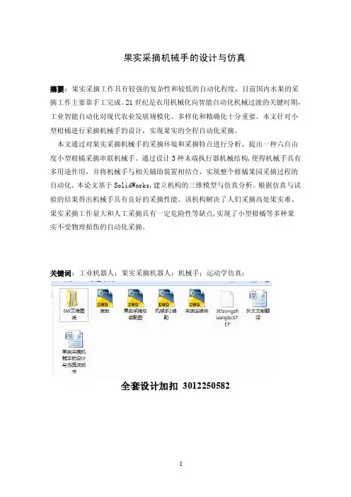
果实采摘机械手的设计与仿真
摘要:果实采摘工作具有较强的复杂性和较低的自动化程度,目前国内水果的采
摘工作主要靠手工完成。21 世纪是农用机械化向智能自动化机械过渡的关键时期,
工业智能自动化对现代农业发展规模化、多样化和精确化十分重要。本文针对小
型柑橘进行采摘机械手的设计,实现果实的全程自动化采摘。
本文通过对果实采摘机械手的采摘环境和采摘特点进行分析,提出一种六自由
manipulator, and puts forwards to a six-degree-of- freedom small citrus picking series
manipulator. Through the design of three kinds of end executor mechanical structure,
contextcapture_2023_中文说明文档_概述及范文模板

contextcapture 2023 中文说明文档概述及范文模板1. 引言1.1 概述:本文是针对contextcapture 2023软件的中文说明文档,旨在为用户提供对该软件的综合了解和操作指南。
通过读取本文,用户将了解到contextcapture 2023的功能特点、适用范围以及主要使用方法。
1.2 文章结构:本文分为引言、正文、章节三、章节四和结论五个部分。
引言部分主要介绍了文章的概要内容和结构安排,使读者能够对文章有一个整体的把握。
接下来的正文部分将详细介绍contextcapture 2023软件的各项功能及其使用方法。
章节三和章节四将进一步扩展讨论有关该软件的相关主题。
最后,在结论部分,我们将对全文进行总结,并提供一些额外信息供读者参考。
1.3 目的:本文的目标是帮助用户全面了解contextcapture 2023软件,并掌握其基本使用方法。
通过阅读本文,用户可以快速上手并运用该软件进行相关工作。
我们将尽力提供清晰明了、简洁直观且易于理解的说明,以确保用户能够充分利用contextcapture 2023的强大功能。
2. 正文正文部分将详细介绍ContextCapture 2023的功能和用法。
ContextCapture 是一款先进的三维现实建模软件,能够从不同来源的数据中生成高质量的3D模型。
该软件结合了无人机航拍、地面摄影测量、激光扫描等技术,可以应用于城市规划、土地管理、遗址保护等领域。
2.1 数据导入ContextCapture 2023支持多种数据格式的导入,包括图像序列、点云数据以及实时流媒体数据。
用户可以通过简单的操作将这些不同源头的数据导入到软件中进行处理。
2.2 图像处理在导入数据后,ContextCapture 2023会自动对图像进行校正和处理,以提升三维重建质量。
该软件具备先进的图像匹配和特征提取算法,能够快速而准确地识别出每张图像之间的相似性,并根据图片间共同特征进行匹配。
纯电车型整车性能集成探究
86AUTO TIMENEW ENERGY AUTOMOBILE | 新能源汽车纯电车型整车性能集成探究1 引言随着物质文明进步,消费者对汽车的需求已由最初的运输和代步工具转变成了更高层次的要求。
除空间等基本需求外,消费者关注点逐渐转变到汽车内在性能好坏,如动力性、安全性、可靠性等。
汽车开发方式也顺理成章实现了由结构开发向性能开发为主导的转变。
汽车性能在整车开发过程扮演着越来越重要的角色,整车性能集成也尤为关键,它决定了整车最终呈现的状态。
而现今在越来越多纯电车型的涌现,纯电车型性能技术也应运而生。
因此,在纯电车型开发中,探究整车性能集成技术的应用尤为重要,它与传统燃油车型的要求不同,对纯电车型进行区别探究,可制定出更具适应性的开发方案。
2 整车性能集成技术概述汽车性能是指和整车产品有关的各项性能指标的综合体,是用户感知和判断产品优劣的重要参考,性能来源于用户的使用感受,是用户需求的直接体现。
汽车结构是汽车性能的载体,而汽车性能是汽车结构的表现。
纯电车型汽车性能与传统燃油车型汽车性能相比,有相同的部分,亦有不同的部分,新增性能属性有:充电显示及交互,纯电续航,充/放电性能、电池特性等,传统性能模块主要区别在于动力系统不同,对应的动力系统性能呈现不同,这是最大的区别。
当然,动力系统的不同也会影响到其他性能的设计,比如动力系统相关的冷却性能,采用的冷却设计方案不同,环保性能中排放,因为使用电池电机电控的使用,没有废气排放,故而在纯电项目是不适用,底盘和NVH 性能的呈现也有不同等等,具体下一节中会详述各部分的不同,见图1。
3 纯电车型整车性能集成技术内容纯电车型与传统燃油车型并未完全创新,有相同之处,也有差异化的属性,与传动能源车型有差异化属性包括:动力性能,驾驶性能,传动系统性能,空调,制动,NVH 性能等,新能源车型新增性能属性有:充电显示及交互,纯电续航,充/放电性能、电池特性等。
纯电车型整车性能集成分类如下表1。
SIMATIC Visualization Architect系统手册
危险 表示如果不采取相应的小心措施,将会导致死亡或者严重的人身伤害。
警告 表示如果不采取相应的小心措施,可能导致死亡或者严重的人身伤害。
小心 表示如果不采取相应的小心措施,可能导致轻微的人身伤害。
注意 表示如果不采取相应的小心措施,可能导致财产损失。
当出现多个危险等级的情况下,每次总是使用最高等级的警告提示。如果在某个警告提示中带有警告可能导致人身 伤害的警告三角,则可能在该警告提示中另外还附带有可能导致财产损失的警告。
安全性信息
1
基本知识
2
SIMATIC
安装
3
TIA-Portal
元素和基本设置
4
SIMATIC Visualization Architect
使用 SiVArc
5
系统手册
使用 SiVArc 表达式
6
参考
7
SiVArc 消息
8
在线帮助打印输出 07/2016
在线帮助打印输出
法律资讯 警告提示系统ቤተ መጻሕፍቲ ባይዱ
为了您的人身安全以及避免财产损失,必须注意本手册中的提示。人身安全的提示用一个警告三角表示,仅与财产 损失有关的提示不带警告三角。警告提示根据危险等级由高到低如下表示。
2.3
关于使用 SiVArc 的基础知识..........................................................................................17
2.4
支持的设备......................................................................................................................21
EICAD3.0说明.pdf
EICAD简介目录1. 目录 (2)2. 1.系统概况 (3)2.1 1.1 创新道路设计领域的“建筑信息模型BIM”理念 (4)2.2 1.2 构建智能化实体及其内部关联 (4)2.3 1.3 高交互式和可视化地创建道路模型 (4)2.4 1.4 出色的可视化性能 (4)2.5 1.5 突破内存限制的64位操作系统,支持大型工程设计项目 (4)3. 2.数字地面模型 (4)3.1 2.1 支持大型数据集、多种显示模式的数模实体 (6)3.2 2.2 MeshEditor程序支持快捷、高效的模型编辑 (6)3.3 2.3 支持道路设计过程中实时剖切 (6)3.4 2.4 进行场地整平设计 (6)4. 3.路线平面设计 (6)4.1 3.1 智能化“道路中线”实体 (7)4.2 3.2 更加快捷的平面设计和编辑功能 (7)4.3 3.3 实时联动设计 (7)5. 4.纵断面设计 (7)5.1 4.1 “拉坡图”实体 (8)5.2 4.2 智能化“竖曲线”实体 (8)5.3 4.3 实时变化的监视断面 (8)6. 5.横断面设计 (8)6.1 5.1 路基模板实体 (9)6.2 5.2 超高实体 (9)6.3 5.3 边坡模板实体 (9)6.4 5.4 道路模型实体 (9)7. 6.图表生成 (9)7.1 6.1 智能“图框”实体 (10)7.2 6.2 图纸集管理 (10)1. 目录1 系统概况(见 [标题编号.])1.1 创新道路设计领域的"建筑信息模型BIM"理念1.2 构建智能化实体及其内部关联1.3 高交互式和可视化地创建道路模型1.4 出色的可视化性能1.5 突破内存限制的64位操作系统,支持大型工程设计项目2 数字地面模型(见 [标题编号.])2.1 支持大型数据集、多种显示模式的数模实体2.2 MeshEditor程序支持快捷、高效的模型编辑2.3 支持道路设计过程中实时剖切2.4 进行场地整平设计3 路线平面设计(见 [标题编号.])3.1 智能化"道路中线"实体3.2 更加快捷的平面设计和编辑功能3.3 实时联动设计4 纵断面设计(见 [标题编号.])4.1 "拉坡图"实体4.2 智能化"竖曲线"实体4.3 实时变化的监视断面5 横断面设计(见 [标题编号.])5.1 路基模板实体5.2 超高实体5.3 边坡模板实体5.4 道路模型实体6 图表生成(见 [标题编号.])6.1 智能"图框"实体6.2 图纸集管理2. 1.系统概况1. 系统概况狄诺尼集成交互式道路与立交设计系统EICAD 3.0汇集了近十年来公路与城市道路设计领域的理论创新成果;全面贯彻了全三维化设计的新理念,设计过程中可实时观察道路模型的三维状态;实现了一套智能化自定义实体及其底层联动机制,通过夹点编辑和双击编辑功能,设计命令大大减少,而设计功能更加丰富,可大幅度提高设计效率。
利维顿制造公司Provolt房间控制器(PRC)说明书
Leviton Manufacturing Co., Inc. Lighting & Controls10385 SW Avery Street, Tualatin, OR 97062 tel 800-736-6682 tech line (6:00AM-4:00PM PT Mon-Fri) 800-959-6004 ©2023 Leviton Manufacturing Co., Inc. All rights reserved. Subject to change without notice.DescriptionThe Leviton exclusive Provolt™ Room Controllers (PRC) offer high performance, code compliant, advanced room configuration in one easy-to-install device. Installers can download the Provolt Bluetooth Mobile App for quick-and-easy room configuration and testing with any iOS or Android device.The PRC’s features meet advanced design requirements for single room/area dimming applications offering easyconfiguration and operational testing for single 0-10V manual dimming zone, occupancy sensing, plug load control, partial-ON, partial-OFF, two daylight harvesting zones, area control and demand response.Automatic Room ConfigurationThe industry-exclusive enhanced automation feature optimizes lighting by monitoring and adjusting to new technology introduced to a room while preventinginterferences to the PRCs signal during the life of the product.• Initial power-up automatically starts room specific calibration• Automatic Daylight Harvesting Calibration (AutoCal)• Continual room optimization• Room behavior and trending data adjusts automatic OFF timer• Ultrasonic (U/S) sensor sensitivity adjustments to reduce false ONs and false OFFs• U/S processing keeps room lighting operational by detecting other U/S sources and adjusting or shutting lights OFF as required• Uploading and downloading room configuration templates reduces errors, speeds installation and testing and troubleshootingProvolt™ 0-10V Dimming Room Controllers (PRC)Easy-to-Install Self-Contained Lighting Control SolutionFeatures• Can be used to comply with IECC, ASHRAE 90.1. and 2022 Title 24, Part 6- Occupancy/vacancy sensing - 0-10V dimming - Daylight harvesting - Partial-ON, partial-OFF - Demand response- Receptacle control requirements• Available in 450 to 2,000 square foot field-of-view units• Uses U/S (Doppler shift) motion detection gives maximum sensitivity and PIR motion detection and prevents false triggers• Manual area control available for 3-way/multi-wayapplications with the Provolt (PL VSW) keypads (must all be same style)• Manual control for single area dimming (dim bothprimary and secondary daylighting zones up and down simultaneously)• AutoCal feature—Digital Daylighting Level automatically calibrates photocell to specified lighting design• Simplified daylight harvesting control of primary andsecondary daylighting zones with full range 0-10V dimming • Primary zone dimmed up and down from photocell• Secondary zone dimmed up and down with offset from primary zone• Two light pipes are included for both open (angled) and closed loop (flat and angled) daylight harvesting• The angled light pipe provides directional fine tuning and alignment to natural light source for closed loop applications• Ladderless Commissioning™ and programming through Bluetooth-enabled iOS or Android smart devices• Visual RGB LED indicator for status and troubleshootingLight PipePRC DaylightingScreen PRC Status ScreenFeatures, cont’d• Easily test room configuration using a smart device as a calibration, measurement and testing tool• Connect a OPP20 power pack to a two circuit room controller for a plug load control solution• Industry-exclusive H.I.S. (High Inrush Stability) technology • Tested to 1.2 million switching cycles under standard loads• Zero-crossing circuitry for extended life of the relay • Latching relay provides dependability and robust performance for all load types• Industry-exclusive “fail safe” circuitry: in the event ofproduct failure, return-to-close feature causes the relay to default ON which eliminates life safety concerns App FeaturesEasily download the Provolt Bluetooth Mobile App to an iOS or Android smart device and pair to the PRC using Bluetooth technology.• Create custom templates for easy multi-room replication of room controller settings• Select between Auto-ON/Auto-OFF and Manual-ON/Auto-OFF• Enable/disable partial-ON and partial-OFF and set the partial-ON and partial-OFF levels • Set occupancy sensor time-out• Set secondary timer for partial-OFF to full-OFF state (infinity by default)• Set vacancy and secondary timeouts between 30s-30mins • Enable/disable receptacle/HVAC control for secondary relay•Set the offset of the secondary daylight zone based off increase/decrease DDL, fade rate, dim to min, dim to OFF • Manually adjust DDL set point to fine tune for room type after auto-configuration• Over-the-Air (OTA) updates: allows userto update PRC firmware in the field via the App • Reset to factory defaultsPlacement DiagramsClosed Loop Mode• Angled light pipe angled toward work surface• Mounted 12 feet of window • Mounted in locationoptimized to prevent falseoccupancy triggersSingle Room Single Daylighting ControlLine VoltageSensorLine Voltage (both lines MUST be fed from the sam Line 1 (L1)Load 2 IN (L2)Neut. NLine120-277VAC,50/60HzLoad 20-10V runs CLASS 1 or CLASS 2 per NEC staSingle Room Multiple Daylighting ControlLineNeutral SensorLine (L1)Load OUT (L1)Neut. NLoad Line120-277VAC,50/60HzLine Voltage (both lines MUST be fed from the same phase)0-10V runs CLASS 1 or CLASS 2 per NEC standardsWiring DiagramsLeviton Manufacturing Co., Inc. Lighting & Controls10385 SW Avery Street, Tualatin, OR 97062 tel 800-736-6682 tech line (6:00AM-4:00PM PT Mon-Fri) 800-959-6004 ©2023 Leviton Manufacturing Co., Inc. All rights reserved. Subject to change without notice.Field of View DiagramsExtended Range - BlackMulti-Tech Models - extended range,black lens15151010550TOP VIEWMid-Range Lens - Red*See the PRC Application Cookbook for additional wiring diagrams.Installation• Easy installation into junction boxes with Leviton-exclusive screw guides, coasters and terminal blocks • Front cover snaps on and off for ease of installation• Sensors conveniently mount to a standard 4” x 4” square or octagon electrical box per NEC standards. The square junction box requires a mud ring.• Color matching via paintable front cover4”x4” Cosmetic AdapterAngled light pipeScrew GuidesFlat light pipePL VSW-1LW PL VSW-2LW PL VSW-4LWProvolt Low Voltage Keypads are available in 1, 2, and 4 button options. See ordering information or the Provolt Low Voltage Keypads Data Sheet for more information.SpecificationsLeviton Manufacturing Co., Inc. Lighting & Controls10385 SW Avery Street, Tualatin, OR 97062tel800-736-6682 tech line (6:00AM-4:00PM PT Mon-Fri) 800-959-6004 ©2023 Leviton Manufacturing Co., Inc. All rights reserved. Subject to change without notice.*Replace x to indicate color: White (W), Ivory (I), Light Almond (T), Gray (G), Black (E) and Red (R). Color change kits are blank and available for custom engraving for button markings.G-9661K/F23-mmREV JUL 2023Leviton Manufacturing Co., Inc. Lighting & Controls10385 SW Avery Street, Tualatin, OR 97062 tel 800-736-6682 tech line (6:00AM-4:00PM PT Mon-Fri) 800-959-6004Leviton Manufacturing Co., Inc. Global Headquarters201 North Service Road, Melville, NY 11747-3138 tel 800-323-8920 tech line (8:00AM-10:00PM ET Mon-Fri, 9:00AM-7:00PM ET Sat, 9:00AM-5:00PM ET Sun) 800-824-3005Visit our Website at: /provolt©2023 Leviton Manufacturing Co., Inc. All rights reserved. Subject to change without notice.。
Glider Flying Handbook说明书
Glider Flying Handbook2013U.S. Department of TransportationFEDERAL AVIATION ADMINISTRATIONFlight Standards Servicei iPrefaceThe Glider Flying Handbook is designed as a technical manual for applicants who are preparing for glider category rating and for currently certificated glider pilots who wish to improve their knowledge. Certificated flight instructors will find this handbook a valuable training aid, since detailed coverage of aeronautical decision-making, components and systems, aerodynamics, flight instruments, performance limitations, ground operations, flight maneuvers, traffic patterns, emergencies, soaring weather, soaring techniques, and cross-country flight is included. Topics such as radio navigation and communication, use of flight information publications, and regulations are available in other Federal Aviation Administration (FAA) publications.The discussion and explanations reflect the most commonly used practices and principles. Occasionally, the word “must” or similar language is used where the desired action is deemed critical. The use of such language is not intended to add to, interpret, or relieve a duty imposed by Title 14 of the Code of Federal Regulations (14 CFR). Persons working towards a glider rating are advised to review the references from the applicable practical test standards (FAA-G-8082-4, Sport Pilot and Flight Instructor with a Sport Pilot Rating Knowledge Test Guide, FAA-G-8082-5, Commercial Pilot Knowledge Test Guide, and FAA-G-8082-17, Recreational Pilot and Private Pilot Knowledge Test Guide). Resources for study include FAA-H-8083-25, Pilot’s Handbook of Aeronautical Knowledge, FAA-H-8083-2, Risk Management Handbook, and Advisory Circular (AC) 00-6, Aviation Weather For Pilots and Flight Operations Personnel, AC 00-45, Aviation Weather Services, as these documents contain basic material not duplicated herein. All beginning applicants should refer to FAA-H-8083-25, Pilot’s Handbook of Aeronautical Knowledge, for study and basic library reference.It is essential for persons using this handbook to become familiar with and apply the pertinent parts of 14 CFR and the Aeronautical Information Manual (AIM). The AIM is available online at . The current Flight Standards Service airman training and testing material and learning statements for all airman certificates and ratings can be obtained from .This handbook supersedes FAA-H-8083-13, Glider Flying Handbook, dated 2003. Always select the latest edition of any publication and check the website for errata pages and listing of changes to FAA educational publications developed by the FAA’s Airman Testing Standards Branch, AFS-630.This handbook is available for download, in PDF format, from .This handbook is published by the United States Department of Transportation, Federal Aviation Administration, Airman Testing Standards Branch, AFS-630, P.O. Box 25082, Oklahoma City, OK 73125.Comments regarding this publication should be sent, in email form, to the following address:********************************************John M. AllenDirector, Flight Standards Serviceiiii vAcknowledgmentsThe Glider Flying Handbook was produced by the Federal Aviation Administration (FAA) with the assistance of Safety Research Corporation of America (SRCA). The FAA wishes to acknowledge the following contributors: Sue Telford of Telford Fishing & Hunting Services for images used in Chapter 1JerryZieba () for images used in Chapter 2Tim Mara () for images used in Chapters 2 and 12Uli Kremer of Alexander Schleicher GmbH & Co for images used in Chapter 2Richard Lancaster () for images and content used in Chapter 3Dave Nadler of Nadler & Associates for images used in Chapter 6Dave McConeghey for images used in Chapter 6John Brandon (www.raa.asn.au) for images and content used in Chapter 7Patrick Panzera () for images used in Chapter 8Jeff Haby (www.theweatherprediction) for images used in Chapter 8National Soaring Museum () for content used in Chapter 9Bill Elliot () for images used in Chapter 12.Tiffany Fidler for images used in Chapter 12.Additional appreciation is extended to the Soaring Society of America, Inc. (), the Soaring Safety Foundation, and Mr. Brad Temeyer and Mr. Bill Martin from the National Oceanic and Atmospheric Administration (NOAA) for their technical support and input.vv iPreface (iii)Acknowledgments (v)Table of Contents (vii)Chapter 1Gliders and Sailplanes ........................................1-1 Introduction....................................................................1-1 Gliders—The Early Years ..............................................1-2 Glider or Sailplane? .......................................................1-3 Glider Pilot Schools ......................................................1-4 14 CFR Part 141 Pilot Schools ...................................1-5 14 CFR Part 61 Instruction ........................................1-5 Glider Certificate Eligibility Requirements ...................1-5 Common Glider Concepts ..............................................1-6 Terminology...............................................................1-6 Converting Metric Distance to Feet ...........................1-6 Chapter 2Components and Systems .................................2-1 Introduction....................................................................2-1 Glider Design .................................................................2-2 The Fuselage ..................................................................2-4 Wings and Components .............................................2-4 Lift/Drag Devices ...........................................................2-5 Empennage .....................................................................2-6 Towhook Devices .......................................................2-7 Powerplant .....................................................................2-7 Self-Launching Gliders .............................................2-7 Sustainer Engines .......................................................2-8 Landing Gear .................................................................2-8 Wheel Brakes .............................................................2-8 Chapter 3Aerodynamics of Flight .......................................3-1 Introduction....................................................................3-1 Forces of Flight..............................................................3-2 Newton’s Third Law of Motion .................................3-2 Lift ..............................................................................3-2The Effects of Drag on a Glider .....................................3-3 Parasite Drag ..............................................................3-3 Form Drag ...............................................................3-3 Skin Friction Drag ..................................................3-3 Interference Drag ....................................................3-5 Total Drag...................................................................3-6 Wing Planform ...........................................................3-6 Elliptical Wing ........................................................3-6 Rectangular Wing ...................................................3-7 Tapered Wing .........................................................3-7 Swept-Forward Wing ..............................................3-7 Washout ..................................................................3-7 Glide Ratio .................................................................3-8 Aspect Ratio ............................................................3-9 Weight ........................................................................3-9 Thrust .........................................................................3-9 Three Axes of Rotation ..................................................3-9 Stability ........................................................................3-10 Flutter .......................................................................3-11 Lateral Stability ........................................................3-12 Turning Flight ..............................................................3-13 Load Factors .................................................................3-13 Radius of Turn ..........................................................3-14 Turn Coordination ....................................................3-15 Slips ..........................................................................3-15 Forward Slip .........................................................3-16 Sideslip .................................................................3-17 Spins .........................................................................3-17 Ground Effect ...............................................................3-19 Chapter 4Flight Instruments ...............................................4-1 Introduction....................................................................4-1 Pitot-Static Instruments ..................................................4-2 Impact and Static Pressure Lines................................4-2 Airspeed Indicator ......................................................4-2 The Effects of Altitude on the AirspeedIndicator..................................................................4-3 Types of Airspeed ...................................................4-3Table of ContentsviiAirspeed Indicator Markings ......................................4-5 Other Airspeed Limitations ........................................4-6 Altimeter .....................................................................4-6 Principles of Operation ...........................................4-6 Effect of Nonstandard Pressure andTemperature............................................................4-7 Setting the Altimeter (Kollsman Window) .............4-9 Types of Altitude ......................................................4-10 Variometer................................................................4-11 Total Energy System .............................................4-14 Netto .....................................................................4-14 Electronic Flight Computers ....................................4-15 Magnetic Compass .......................................................4-16 Yaw String ................................................................4-16 Inclinometer..............................................................4-16 Gyroscopic Instruments ...............................................4-17 G-Meter ........................................................................4-17 FLARM Collision Avoidance System .........................4-18 Chapter 5Glider Performance .............................................5-1 Introduction....................................................................5-1 Factors Affecting Performance ......................................5-2 High and Low Density Altitude Conditions ...........5-2 Atmospheric Pressure .............................................5-2 Altitude ...................................................................5-3 Temperature............................................................5-3 Wind ...........................................................................5-3 Weight ........................................................................5-5 Rate of Climb .................................................................5-7 Flight Manuals and Placards ..........................................5-8 Placards ......................................................................5-8 Performance Information ...........................................5-8 Glider Polars ...............................................................5-8 Weight and Balance Information .............................5-10 Limitations ...............................................................5-10 Weight and Balance .....................................................5-12 Center of Gravity ......................................................5-12 Problems Associated With CG Forward ofForward Limit .......................................................5-12 Problems Associated With CG Aft of Aft Limit ..5-13 Sample Weight and Balance Problems ....................5-13 Ballast ..........................................................................5-14 Chapter 6Preflight and Ground Operations .......................6-1 Introduction....................................................................6-1 Assembly and Storage Techniques ................................6-2 Trailering....................................................................6-3 Tiedown and Securing ................................................6-4Water Ballast ..............................................................6-4 Ground Handling........................................................6-4 Launch Equipment Inspection ....................................6-5 Glider Preflight Inspection .........................................6-6 Prelaunch Checklist ....................................................6-7 Glider Care .....................................................................6-7 Preventive Maintenance .............................................6-8 Chapter 7Launch and Recovery Procedures and Flight Maneuvers ............................................................7-1 Introduction....................................................................7-1 Aerotow Takeoff Procedures .........................................7-2 Signals ........................................................................7-2 Prelaunch Signals ....................................................7-2 Inflight Signals ........................................................7-3 Takeoff Procedures and Techniques ..........................7-3 Normal Assisted Takeoff............................................7-4 Unassisted Takeoff.....................................................7-5 Crosswind Takeoff .....................................................7-5 Assisted ...................................................................7-5 Unassisted...............................................................7-6 Aerotow Climb-Out ....................................................7-6 Aerotow Release.........................................................7-8 Slack Line ...................................................................7-9 Boxing the Wake ......................................................7-10 Ground Launch Takeoff Procedures ............................7-11 CG Hooks .................................................................7-11 Signals ......................................................................7-11 Prelaunch Signals (Winch/Automobile) ...............7-11 Inflight Signals ......................................................7-12 Tow Speeds ..............................................................7-12 Automobile Launch ..................................................7-14 Crosswind Takeoff and Climb .................................7-14 Normal Into-the-Wind Launch .................................7-15 Climb-Out and Release Procedures ..........................7-16 Self-Launch Takeoff Procedures ..............................7-17 Preparation and Engine Start ....................................7-17 Taxiing .....................................................................7-18 Pretakeoff Check ......................................................7-18 Normal Takeoff ........................................................7-19 Crosswind Takeoff ...................................................7-19 Climb-Out and Shutdown Procedures ......................7-19 Landing .....................................................................7-21 Gliderport/Airport Traffic Patterns and Operations .....7-22 Normal Approach and Landing ................................7-22 Crosswind Landing ..................................................7-25 Slips ..........................................................................7-25 Downwind Landing ..................................................7-27 After Landing and Securing .....................................7-27viiiPerformance Maneuvers ..............................................7-27 Straight Glides ..........................................................7-27 Turns.........................................................................7-28 Roll-In ...................................................................7-29 Roll-Out ................................................................7-30 Steep Turns ...........................................................7-31 Maneuvering at Minimum Controllable Airspeed ...7-31 Stall Recognition and Recovery ...............................7-32 Secondary Stalls ....................................................7-34 Accelerated Stalls .................................................7-34 Crossed-Control Stalls ..........................................7-35 Operating Airspeeds .....................................................7-36 Minimum Sink Airspeed ..........................................7-36 Best Glide Airspeed..................................................7-37 Speed to Fly ..............................................................7-37 Chapter 8Abnormal and Emergency Procedures .............8-1 Introduction....................................................................8-1 Porpoising ......................................................................8-2 Pilot-Induced Oscillations (PIOs) ..............................8-2 PIOs During Launch ...................................................8-2 Factors Influencing PIOs ........................................8-2 Improper Elevator Trim Setting ..............................8-3 Improper Wing Flaps Setting ..................................8-3 Pilot-Induced Roll Oscillations During Launch .........8-3 Pilot-Induced Yaw Oscillations During Launch ........8-4 Gust-Induced Oscillations ..............................................8-5 Vertical Gusts During High-Speed Cruise .................8-5 Pilot-Induced Pitch Oscillations During Landing ......8-6 Glider-Induced Oscillations ...........................................8-6 Pitch Influence of the Glider Towhook Position ........8-6 Self-Launching Glider Oscillations During Powered Flight ...........................................................8-7 Nosewheel Glider Oscillations During Launchesand Landings ..............................................................8-7 Tailwheel/Tailskid Equipped Glider Oscillations During Launches and Landings ..................................8-8 Aerotow Abnormal and Emergency Procedures ............8-8 Abnormal Procedures .................................................8-8 Towing Failures........................................................8-10 Tow Failure With Runway To Land and Stop ......8-11 Tow Failure Without Runway To Land BelowReturning Altitude ................................................8-11 Tow Failure Above Return to Runway Altitude ...8-11 Tow Failure Above 800' AGL ..............................8-12 Tow Failure Above Traffic Pattern Altitude .........8-13 Slack Line .................................................................8-13 Ground Launch Abnormal and Emergency Procedures ....................................................................8-14 Abnormal Procedures ...............................................8-14 Emergency Procedures .............................................8-14 Self-Launch Takeoff Emergency Procedures ..............8-15 Emergency Procedures .............................................8-15 Spiral Dives ..................................................................8-15 Spins .............................................................................8-15 Entry Phase ...............................................................8-17 Incipient Phase .........................................................8-17 Developed Phase ......................................................8-17 Recovery Phase ........................................................8-17 Off-Field Landing Procedures .....................................8-18 Afterlanding Off Field .............................................8-20 Off-Field Landing Without Injury ........................8-20 Off-Field Landing With Injury .............................8-20 System and Equipment Malfunctions ..........................8-20 Flight Instrument Malfunctions ................................8-20 Airspeed Indicator Malfunctions ..........................8-21 Altimeter Malfunctions .........................................8-21 Variometer Malfunctions ......................................8-21 Compass Malfunctions .........................................8-21 Glider Canopy Malfunctions ....................................8-21 Broken Glider Canopy ..........................................8-22 Frosted Glider Canopy ..........................................8-22 Water Ballast Malfunctions ......................................8-22 Retractable Landing Gear Malfunctions ..................8-22 Primary Flight Control Systems ...............................8-22 Elevator Malfunctions ..........................................8-22 Aileron Malfunctions ............................................8-23 Rudder Malfunctions ............................................8-24 Secondary Flight Controls Systems .........................8-24 Elevator Trim Malfunctions .................................8-24 Spoiler/Dive Brake Malfunctions .........................8-24 Miscellaneous Flight System Malfunctions .................8-25 Towhook Malfunctions ............................................8-25 Oxygen System Malfunctions ..................................8-25 Drogue Chute Malfunctions .....................................8-25 Self-Launching Gliders ................................................8-26 Self-Launching/Sustainer Glider Engine Failure During Takeoff or Climb ..........................................8-26 Inability to Restart a Self-Launching/SustainerGlider Engine While Airborne .................................8-27 Self-Launching Glider Propeller Malfunctions ........8-27 Self-Launching Glider Electrical System Malfunctions .............................................................8-27 In-flight Fire .............................................................8-28 Emergency Equipment and Survival Gear ...................8-28 Survival Gear Checklists ..........................................8-28 Food and Water ........................................................8-28ixClothing ....................................................................8-28 Communication ........................................................8-29 Navigation Equipment ..............................................8-29 Medical Equipment ..................................................8-29 Stowage ....................................................................8-30 Parachute ..................................................................8-30 Oxygen System Malfunctions ..................................8-30 Accident Prevention .....................................................8-30 Chapter 9Soaring Weather ..................................................9-1 Introduction....................................................................9-1 The Atmosphere .............................................................9-2 Composition ...............................................................9-2 Properties ....................................................................9-2 Temperature............................................................9-2 Density ....................................................................9-2 Pressure ...................................................................9-2 Standard Atmosphere .................................................9-3 Layers of the Atmosphere ..........................................9-4 Scale of Weather Events ................................................9-4 Thermal Soaring Weather ..............................................9-6 Thermal Shape and Structure .....................................9-6 Atmospheric Stability .................................................9-7 Air Masses Conducive to Thermal Soaring ...................9-9 Cloud Streets ..............................................................9-9 Thermal Waves...........................................................9-9 Thunderstorms..........................................................9-10 Lifted Index ..........................................................9-12 K-Index .................................................................9-12 Weather for Slope Soaring .......................................9-14 Mechanism for Wave Formation ..............................9-16 Lift Due to Convergence ..........................................9-19 Obtaining Weather Information ...................................9-21 Preflight Weather Briefing........................................9-21 Weather-ReIated Information ..................................9-21 Interpreting Weather Charts, Reports, andForecasts ......................................................................9-23 Graphic Weather Charts ...........................................9-23 Winds and Temperatures Aloft Forecast ..............9-23 Composite Moisture Stability Chart .....................9-24 Chapter 10Soaring Techniques ..........................................10-1 Introduction..................................................................10-1 Thermal Soaring ...........................................................10-2 Locating Thermals ....................................................10-2 Cumulus Clouds ...................................................10-2 Other Indicators of Thermals ................................10-3 Wind .....................................................................10-4 The Big Picture .....................................................10-5Entering a Thermal ..............................................10-5 Inside a Thermal.......................................................10-6 Bank Angle ...........................................................10-6 Speed .....................................................................10-6 Centering ...............................................................10-7 Collision Avoidance ................................................10-9 Exiting a Thermal .....................................................10-9 Atypical Thermals ..................................................10-10 Ridge/Slope Soaring ..................................................10-10 Traps ......................................................................10-10 Procedures for Safe Flying .....................................10-12 Bowls and Spurs .....................................................10-13 Slope Lift ................................................................10-13 Obstructions ...........................................................10-14 Tips and Techniques ...............................................10-15 Wave Soaring .............................................................10-16 Preflight Preparation ...............................................10-17 Getting Into the Wave ............................................10-18 Flying in the Wave .................................................10-20 Soaring Convergence Zones ...................................10-23 Combined Sources of Updrafts ..............................10-24 Chapter 11Cross-Country Soaring .....................................11-1 Introduction..................................................................11-1 Flight Preparation and Planning ...................................11-2 Personal and Special Equipment ..................................11-3 Navigation ....................................................................11-5 Using the Plotter .......................................................11-5 A Sample Cross-Country Flight ...............................11-5 Navigation Using GPS .............................................11-8 Cross-Country Techniques ...........................................11-9 Soaring Faster and Farther .........................................11-11 Height Bands ..........................................................11-11 Tips and Techniques ...............................................11-12 Special Situations .......................................................11-14 Course Deviations ..................................................11-14 Lost Procedures ......................................................11-14 Cross-Country Flight in a Self-Launching Glider .....11-15 High-Performance Glider Operations and Considerations ............................................................11-16 Glider Complexity ..................................................11-16 Water Ballast ..........................................................11-17 Cross-Country Flight Using Other Lift Sources ........11-17 Chapter 12Towing ................................................................12-1 Introduction..................................................................12-1 Equipment Inspections and Operational Checks .........12-2 Tow Hook ................................................................12-2 Schweizer Tow Hook ...........................................12-2x。
DVP-ES2 说明书
DVP-ES2 操作手冊 - 模組篇目錄1類比輸入模組 DVP04AD-E21.1 A/D轉換概念................................................................................................................1-21.2 產品外觀及各部介紹.....................................................................................................1-21.3 外部配線.......................................................................................................................1-31.4 規格..............................................................................................................................1-41.5 控制暫存器CR (Control Register)...............................................................................1-61.6 A/D 轉換特性曲線......................................................................................................1-141.7 應用範例.....................................................................................................................1-23 2類比輸出模組 DVP02/04DA-E22.1 D/A轉換概念................................................................................................................2-22.2 產品外觀及各部介紹.....................................................................................................2-22.3 外部配線.......................................................................................................................2-32.4 規格..............................................................................................................................2-42.5 控制暫存器CR (Control Register)...............................................................................2-52.6 D/A 轉換特性曲線......................................................................................................2-142.7 應用範例.....................................................................................................................2-19 3類比輸入/輸出混合模組DVP06XA-E23.1 A/D及D/A轉換概念....................................................................................................3-23.2 產品外觀及各部介紹.....................................................................................................3-23.3 外部配線.......................................................................................................................3-33.4 規格..............................................................................................................................3-43.5 控制暫存器CR (Control Register)...............................................................................3-73.6 A/D及D/A轉換特性曲線...........................................................................................3-183.7 應用範例.....................................................................................................................3-34 4溫度量測模組 DVP04PT-E24.1 白金感溫電阻基本概念.................................................................................................4-24.2 產品外觀及各部介紹.....................................................................................................4-24.3 外部配線.......................................................................................................................4-34.4 規格..............................................................................................................................4-44.5 控制暫存器CR (Control Register)...............................................................................4-5i4.6 PT轉換特性曲線.......................................................................................................4-184.7 應用範例....................................................................................................................4-204.8 PID 功能...................................................................................................................4-22 5溫度量測模組 DVP04TC-E25.1 熱電耦溫度感測器概念................................................................................................5-25.2 產品外觀及各部介紹....................................................................................................5-35.3 外部配線......................................................................................................................5-45.4 規格.............................................................................................................................5-55.5 控制暫存器CR (Control Register)...............................................................................5-75.6 TC轉換特性曲線.......................................................................................................5-195.7 應用範例....................................................................................................................5-235.8 PID 功能...................................................................................................................5-255.9 溫度控制器之硬體屬性..............................................................................................5-33 ii1-1類比輸入模組 DVP04AD-E2DVP04AD-E2 類比輸入模組可接受外部4 點類比信號輸入 (電壓或電流皆可), 將之轉換成16位元之數位信號。
- 1、下载文档前请自行甄别文档内容的完整性,平台不提供额外的编辑、内容补充、找答案等附加服务。
- 2、"仅部分预览"的文档,不可在线预览部分如存在完整性等问题,可反馈申请退款(可完整预览的文档不适用该条件!)。
- 3、如文档侵犯您的权益,请联系客服反馈,我们会尽快为您处理(人工客服工作时间:9:00-18:30)。
04/2005N CV C C 2V C C 3GNDRF OUTGNDDETDC1D E T O U TGND RF IN GND VPC1V C C 1V P C 2/3D E T D C 2V B CFigure 1: Block Diagram and PinoutRFS P20232.4 GHz 802.11b/g WLAN Power AmplifierData Sheet - Rev 2.3FEATURES•<3% EVM, 145 mA @ P OUT = +19 dBm with IEEE 802.11g Modulation at 54 Mbps •-38 dBc ACPR 1st Sidelobe at +23 dBm with IEEE 802.11b Modulation at 11 Mbps •-54 dBc ACPR 2nd Sidelobe at +23 dBm with IEEE 802.11b Modulation at 11 Mbps •No RF Matching Required •34 dB of Linear Power Gain•Temperature-Compensated Linear Power DetectorAPPLICATIONS•IEEE 802.11 b/g WLAN • 2.4 GHz Cordless Phones •2.4 GHz ISM EquipmentPRODUCT DESCRIPTIONThe RFS P2023 power amplifier is a high performance InGaP HBT IC designed for transmit applications in the 2.4-2.5 GHz band. The part is matched at the input and output so no additional RF matching components are required off-chip. ThePA exhibits unparalleled linearity and efficiency for both 802.11g and 802.11b WLAN systems. The power detector is temperature compensated on chip enabling a single-ended output voltage. The part is biased by a single +3.3 V supply.RFS P2023Table 1: Pin Description2Data Sheet - Rev 2.304/2005Data Sheet - Rev 2.304/2005RFS P20233ELECTRICAL CHARACTERISTICSTable 2: Absolute Minimum and Maximum RatingsStresses in excess of the absolute ratings may cause permanent damage. Functional operation is not implied under these conditions. Exposure to absolute ratings for extended periods of time may adversely affect reliability.Table 3: Operating RangesThe device may be operated safely over these conditions; however, parametric performance is guaranteed only over the conditions defined in the electrical specifications.RFS P2023Table 4: IEEE 802.11g Modulation, 54 Mbps OFDMCC PC OUTNotes:1. EVM includes noise floor of 1% (-40 dB).Table 5: IEEE 802.11b Modulation,11 Mbps DSSS, CCK(V CC = 3.3 V, V PC = 3.3 V, P OUT = +21 dBm, +25 °C)4Data Sheet - Rev 2.304/2005Data Sheet - Rev 2.304/2005 RFS P20235Table 6: Continuous Wave Signal6Data Sheet - Rev 2.304/2005RFS P2023PERFORMANCE DATAFigure 2:Gain,Current,EVM vs.Output Power at 2.412GHz,3.3V(IEEE 802.11g @54Mbps)12131415161718192021Output Power (dBm)G a i n (d B ),E V M (%)C u r r e n t (m A )Figure 3:Gain,Current vs.Output Power at 2.412GHz,3.3V (IEEE 802.11b Signal @11Mbps)Output Power (dBm)G a i n (d B )C u r r e n t (m A )Figure 4:Gain,Current,EVM vs.Output Power at 2.437GHz,3.3V(IEEE 802.11g @54Mbps)12131415161718192021Output Power (dBm)G a i n (d B ),E V M (%)C u r r e n t (m A )Figure 5:Gain,Current vs.Output Power at 2.437GHz,3.3V (IEEE 802.11b Signal @11Mbps)Output Power (dBm)G a i n (d B )C u r r e n t (m A )Figure 6:Gain,Current,EVM vs.Output Power at 2.462GHz,3.3V(IEEE 802.11g @54Mbps)12131415161718192021Output Power (dBm)G a i n (d B ),E V M (%)C u r r e n t (m A )Figure 7:Gain,Current vs.Output Power at 2.462GHz,3.3V (IEEE 802.11b Signal @11Mbps)Output Power (dBm)G a i n (d B )C u r r e n t (m A )Data Sheet - Rev 2.304/2005RFS P20237Figure 8:Power Detector Voltage vs.Output Power at 2.412GHz,3.3V(IEEE 802.11g @54Mbps)Output Power (dBm)D e t e c t o r O u t p u t (V )Figure 9:Power Detector Voltage vs.Output Power at 2.412GHz,3.3V(IEEE 802.11b @11Mbps)Output Power (dBm)D e t e c t o r O u t p u t (V )Figure 10:Power Detector Voltage vs.Output Power at 2.437GHz,3.3V(IEEE 802.11g @54Mbps)12131415161718192021Output Power (dBm)D e t e c t o r O u t p u t (V )Figure 11:Power Detector Voltage vs.Output Power at 2.437GHz,3.3V(IEEE 802.11b @11Mbps)Output Power (dBm)D e t e c t o r O u t p u t (V )Figure 12:Power Detector Voltage vs.Output Power at 2.462GHz,3.3V(IEEE 802.11g @54Mbps)Output Power (dBm)D e t e c t o r V o l t a g e (V )Figure 13:Power Detector Voltage vs.Output Power at 2.462GHz,3.3V(IEEE 802.11b @11Mbps)1617181920212223Output Power (dBm)D e t e c t o r O u t p u t (V )8Data Sheet - Rev 2.304/2005RFS P2023Figure 18:S-Parameter Data S11and S22,3.3VFrequency (GHz)S 11(d B )Figure 14:ACPR Sidelobes vs.Output Power at 2.412GHz,3.3V(IEEE 802.11b @11Mbps)Output Power (dBm)R e l a t i v e P o w e r (d B r )Figure 15:ACPR Sidelobes vs.Output Power at 2.462GHz,3.3V(IEEE 802.11b @11Mbps)Output PowerR e l a t i v e P o w e r (d B r )Figure 16:+23dBm Output Powerat 2.412GHz,3.3V (IEEE 802.11b @11Mbps)2.382.39 2.4 2.41 2.42 2.43 2.44 2.45Frequency (GHz)R e l a t i v e P o w e r (d B r )Figure 17:+23dBm Output Powerat 2.462GHz,3.3V (IEEE 802.11b @11Mbps)Frequency (GHz)Data Sheet - Rev 2.304/2005RFS P20239APPLICATION INFORMATIONR1010+/-5%C40.1uF +/-10%C11100pF +/-5%C91000pF +/-10%DNPU1RFS P2023GND 1RF IN 2GND 3VPC14V b c c5V p c 2/36D E T O U T8DETDC19D E T D C 27GND 10GND 12RF OUT11V C C 313V C C 214N C15V C C 116GND25L110nH +/-5%R6430+/-5%R44.7K C100.47uF +/-10%R210+/-5%C610pF +/-0.5pF C710pF +/-0.5pFR930+/-5%C510uF 16V +/-20%R175+/-1%R81K +/-5%C10.1uF +/-10%R3806R5806VCCVCCVD2GVPC**NOTES**RF traces should be 18mils wide with 20mils of clearanceDC traces should be 8mils wide with 8mils of clearance DNP =Do Not PlaceRF INRF OUT+/-1%+/-1%+/-5%Figure 19: Recommended Application Circuit10Data Sheet - Rev 2.304/2005RFS P2023PACKAGE OUTLINEFigure 20: Package OutlineAreaRFS P2023 NOTESRFS P2023ORDERING INFORMATIONANADIGICS, Inc.141 Mount Bethel RoadWarren, New Jersey 07059, U.S.A.Tel: +1 (908) 668-5000Fax: +1 (908) 668-5132URL: E-mail: Mktg@IMPORTANT NOTICEANADIGICS, Inc. reserves the right to make changes to its products or to discontinue any product at any time without notice. The product specifications contained in Advanced Product Information sheets and Preliminary Data Sheets are subject to change prior to a product’s formal introduction. Information in Data Sheets have been carefully checked and are assumed to be reliable; however, ANADIGICS assumes no responsibilities for inaccuracies. ANADIGICS strongly urges customers to verify that the information they are using is current before placing orders.WARNINGANADIGICS products are not intended for use in life support appliances, devices or systems. Use of an ANADIGICS product in any such application without written consent is prohibited.。