佛山山明862共面法兰微压变送器或微压压力传感器
DW254 智能差压开关变送器 使用说明书
版本号:V1.0.2DW254智能差压开关变送器使用说明书合肥杜威智能科技股份有限公司目录一、概述 (1)二、功能特点 (1)三、应用场景 (1)四、技术参数 (2)五、工作原理 (2)六、安装尺寸 (2)七、安装方式 (2)八、压力连接 (2)九、操作说明 (2)十、485通信协议 (3)十一、接线说明 (4)十二、菜单及代码 (4)一、概述DW254系列智能差压变送器应用专利的可变电容传感技术,二线制4~20mA信号输出,最小量程0~25Pa,这种MEMS传感器拥有敏感性强以及长期稳定性。
壁挂和嵌入式安装可选,符合洁净室、手术室等洁净环境的GMP标准。
产品美观大方,拥有两路继电器信号输出,可以任意设定报警值,ModBus RTU 485信号输出,方便组网,蜂鸣器报警可选。
二、功能特点⚫反向接线保护⚫4~20mA、两路RCR继电器6A/230VAC信号输出⚫标准ModBus RTU 485信号输出⚫实现低量程而且对测量介质不敏感⚫温度变化自动逐点修正温度漂移⚫低量程输出稳定,潮气灰尘无影响⚫嵌入式圆盘经典外观,轻松升级原有圆形差压表⚫现场可校正,无需返厂增加产品使用年限⚫符合洁净室GMP标准、欧盟及美国FDA标准三、应用场景广泛应用于制药工业、电子洁净厂房、无尘实验室、生物安全实验室、医院负压隔离病房、ICU重症监护室、手术室、负压救护车、生物安全柜等场景;同时适用于智能楼宇、暖通空调机组过滤器监测、VAV及风扇控制、机房通风、消防通道、炉膛风机通风监测控制等行业。
四、技术参数⚫输出信号:4-20mA、RS485 ⚫报警输出:两路继电器报警输出,J1、J2报警指示灯⚫精度:0.8% F.S⚫测量介质:非腐蚀性气体⚫电气连接:PG7防水接头⚫压力连接:1/8″NPT ⚫压力极限:100KPa⚫工作湿度:相对湿度为0-100%⚫工作环境:-20~80℃⚫供电电源:DC 24V AC ⚫功耗:最大50mA五、工作原理杜威DW254智能差压变送器是过程压力通过两侧或一侧的隔离膜片、灌充液传至室的中心测量膜片。
IFM电子压力传感器PT355_PT3560-安装说明书
安装说明书适用于移动应用的电子压力传感器PT355/PT3560/PT95576129/12/211CN21 安全说明• 安装本产品前,请阅读本文档。
确保产品适合您的应用范围,且不受任何限制。
• 如果未遵照操作说明或技术资料,则可能导致人身伤害和/或财产损失。
• 请检查所有应用范围内的产品材料(请参阅“技术资料”)是否与待测介质兼容。
有关 cULus 的有效范围:设备应使用隔离变压器供电,其次级保险丝额定标准为 a) 电压为 0~20 Vrms (0~28.3 Vp) 时,最高 5 amp 或 b) 电压为 20~30 Vrms (28.3~42.4 Vp) 时为 100/Vp。
2 功能和特性该压力传感器可检测系统压力,并将其转换为模拟量输出信号。
• 4 ... 20 mA (PT355x/PT3560) / 0 ...10 V (PT955x)2.1 应用范围• 产品适合在移动车辆中使用。
•压力类型:相对压力请采取适当措施,避免静态和动态压力超过指示的过载压力。
切勿超过指示的爆破压力。
即使在极短时间内超过爆破压力,也会损坏产品。
注意:谨防人身伤害危险!目录1 安全说明 ...............................................................................................................22 功能和特性 ............................................................................................................22.1 应用范围 .........................................................................................................23 安装 ......................................................................................................................34 电气连接 ...............................................................................................................35 比例图 ...................................................................................................................46 技术资料 (5)3CN3 安装安装和拆除产品前,请确保系统未承受任何压力。
NOHMI R23 (能美) 价格表
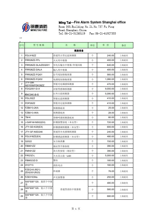
一、序号型号规格名称单位单价备注1FDL918ZZ普通型点型定温探测器个240.00上海能美2FRR28ZZ-FFL火灾用中继器个400.00上海能美3FRR28ZZ-SLA/ZDQ001有电压输出中继器/终端回路个640.00上海能美4FRR28ZZ-DALA输入用中继器个400.00上海能美5FRR28ZZ-FQI01信号线短路隔离器个560.00上海能美6FRR28ZZ-FQI02电源线短路隔离器个1,080.00上海能美7JTY-GM-NSY008/FDK38ZZ智能光电烟感探测器个470.00上海能美8FDG2001-D-X对射型感烟探测器个9,000.00上海能美9FDCZ002-D-X红外火焰探测器个5,090.00上海能美10FDL25ZZ智能定温探测器个410.00上海能美11FDP26ZZ智能差定温探测器个410.00上海能美12FZB013-2KA探测器底座个25.00上海能美13FZB013-4KA探测器底座个28.00上海能美14TM-K带蜂鸣器探测器底座个80.00上海能美15J-SAP-M-NS02(EX)防爆报警按钮(本安型)个720.00上海能美16JTY-GD-K29(EX)防爆感烟探测器(本安型)个600.00上海能美17JTY-GF-NSD246普通型光电感烟探测器个240.00上海能美18FDL918ZZ(EX)防爆感温探测器(本安型)个480.00上海能美19S2022安全隔离栅个700.00上海能美20FBM01ZZ地址型手报按钮个390.00上海能美21FMH01ZZ消火栓按钮(地址型)个390.00上海能美22FIR23Z-L火灾显示盘(LCD)个5,000.00上海能美23FBM023Z-D警铃个160.00上海能美24HY2713消防电话个160.00上海能美25FZEQ16 (R21)ZDQO01(R23)终端器个76.00上海能美26FZE0103Ns声光报警器个250.00上海能美27500*500*120,装四个中继器个480.00上海能美28500*600*120,装六个中继器个580.00上海能美29500*800*120,装八个中继器个680.00上海能美现场设备普通型消防中继器箱Ming Tai—Fire Alarm System Shanghai officeRoom 303,Building No.21,No.737 Fu PingRoad,Shanghai,ChinaTel:86-21-31268119 Fax:86-21-61927353二、报价1本报价有效期为35天,交货期30个工作日。
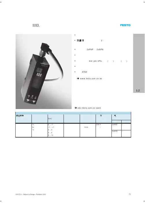
压力传感器SDE3,带显示
显示
订货号 型号
bar 英寸(汞柱) bar 英寸(汞柱) bar 英寸(汞柱) bar bar
bar
bar
540 193 540 194 540 196 540 197 540 199 540 200 540 202 540 203 540 205 540 207 540 209 540 211 540 213
72
Products 2007 – Subject to change – 2007/03
传感器 压力和真空传感器
压力传感器 SDE3, 带显示
技术参数
主要技术参数 结构特点 压力测量范围 测量变量
气接口 显示方式 精度 FS 1) 设定选项 安 装 方 式
[bar] 0 … –1
–1 … +1
订货数据 – 安全夹 规格 M8
M12
订货号 型号 548 067 NEAU-M8-GD 548 068 NEAU-M12-GD
76
Products 2007 – Subject to change – 2007/03
SDE3-V1S-B-HQ4-2P-M8 SDE3-V1S-H-HQ4-2P-M8 SDE3-V1D-B-HQ4-2P-M8 SDE3-V1D-H-HQ4-2P-M8 SDE3-V1Z-B-HQ4-2P-M8 SDE3-V1Z-H-HQ4-2P-M8 SDE3-V1Z-B-HQ4-2N-M8 SDE3-D2D-B-HQ4-2P-M8 SDE3-D2Z-B-HQ4-2P-M8 SDE3-D10S-B-HQ4-2P-M8 SDE3-D10D-B-HQ4-2P-M8 SDE3-D10Z-B-HQ4-2P-M8 SDE3-D10Z-B-HQ4-2N-M8
传感器 压力和真空传感器
维萨拉工业测量产品手册说明书

维萨拉工业测量产品手册湿度 | 温度 | 露点 | 二氧化碳 | 沼气 | 油中水分 | 连续监测系统 |溶解气体分析系统 | 过氧化氢 | 压力 | 气象 | 服务支持观测让世界更美好维萨拉的工业测量业务领域产品能够帮助客户了解工艺过程。
我们的产品为客户提供准确可靠的测量数据,帮助客户做出优化工业过程的决策,从而提高过程效率、产品质量、生产力和产量,同时减少能源消耗、浪费和排放。
我们的监测系统还能帮助客户在受监管的环境中运营,以履行监管合规性。
维萨拉工业测量服务于多种类型的运营环境,从半导体工厂和高层建筑,到发电厂和生命科学实验室,对环境条件的可靠监测是实现成功运营的先决条件。
维萨拉的测量产品和系统广泛应用于监测温度、湿度、露点、气压、二氧化碳、汽化过氧化氢、甲烷、油中水、变压器油中溶解气体和液体浓度等参数。
我们的生命周期服务可在测量仪表的整个使用寿命内提供维护。
作为值得信赖的合作伙伴,我们通过在产品和系统生命周期中保证准确的测量数据来支持客户做出可持续的决策。
本产品目录对我们的产品进行整体的介绍,以帮助您选择适合您需求的产品。
如需更多信息,请通过以下方式联系我们:销售热线:400 810 0126电子邮箱:**********************公司网址:扫描二维码,关注维萨拉企业微信3目 录Indigo系列变送器Indigo200系列数据处理单元 (7)Indigo300数据处理单元 (9)Indigo510数据处理单元 (12)Indigo520数据处理单元 (15)用于抽检和校准的手持设备Indigo80手持式显示表头 (18)HMP80系列手持式湿度和温度探头 (21)DMP80系列手持式露点和温度探头 (23)HM70手持式湿度和温度仪 (26)HUMICAP® 手持式湿度温度仪表HM40系列 (29)DM70手持式露点仪 (33)MM70适用于现场检测的手持式油中微量水分和温度测试仪 (36)湿度和温度用于测量相对湿度的维萨拉HUMICAP® 传感器 (38)如何为高湿度应用选择合适的湿度仪表 (40)Insight PC机软件 (44)HMP1墙面式温湿度探头 (46)HMP3一般用途湿度和温度探头 (48)HMP4相对湿度和温度探头 (51)HMP5相对湿度和温度探头 (54)HMP7相对湿度和温度探头 (57)HMP8相对湿度和温度探头 (60)HMP9紧凑型湿度和温度探头 (63)TMP1温度探头 (66)适用于苛刻环境中湿度测量的HMT330系列温湿度变送器 (68)HMT370EX系列本安型温湿度变送器 (78)HMT310温湿度变送器 (84)HUMICAP® 温湿度变送器HMT120和HMT130 (87)适用于高性能暖通空调应用的HMW90系列湿度与温度变送器 (90)HMD60系列湿度和温度变送器 (92)HMD110/112和HMW110/112湿度和温度变送器 (96)适用于楼宇自动化高精度室外测量的HMS110系列温湿度变送器 (99)HMDW80系列温湿度变送器 (101)适用于楼宇自动化应用室外测量的HMS80系列温湿度变送器 (105)HMM100湿度模块 (107)适用于OEM应用的HMM105数字湿度模块 (109)HMM170温湿度模块 (111)INTERCAP® 温湿度探头HMP60 (113)4INTERCAP® 温湿度探头HMP63 (115)HUMICAP® 温湿度探头HMP110 (117)HUMICAP® 温湿度探头HMP113 (120)SHM40结构湿度测量套件 (122)HMK15湿度校准仪 (125)DTR500太阳辐射和雨水防护罩 (127)HMT330MIK气象安装套件 (129)适用于动力汽轮机进气测量的HMT300TMK汽轮机安装组件 (131)露点Vaisala DRYCAP® 传感器用于测量干燥过程中的湿度 (133)DMP5露点和温度探头 (135)DMP6露点探头 (138)DMP7露点和温度探头 (140)DMP8露点和温度探头 (142)DMT340系列露点和温度变送器 (145)适用于高温应用的DMT345和DMT346露点变送器 (151)DMT152露点变送器 (155)DMT143露点变送器 (157)DMT143L露点变送器 (160)用于冷冻干燥机的DMT132露点变送器 (162)DM70用DSS70A便携式采样系统和采样室 (164)DPT146露点和气压变送器 (166)DPT145多参数变送器 (168)二氧化碳适用于苛刻环境的维萨拉CARBOCAP® 测量传感器 (171)GMP343二氧化碳探头 (173)适用于CO2恒温箱的GMP231二氧化碳探头 (176)GMP251二氧化碳探头 (178)GMP252二氧化碳探头 (181)GM70手持式二氧化碳测试仪 (184)适用于苛刻通风要求应用的GMW90系列二氧化碳及温湿度变送器 (187)适用于智能控制通风系统 (DCV) 的GMW80系列二氧化碳、湿度和温度一体变送器 (190)按需控制通风系统中的GMD20系列二氧化碳变送器 (193)GMD110管道安装式二氧化碳变送器 (195)沼气MGP261多气体探头 (197)MGP262多气体探头 (199)油中水用于测量油中微水的维萨拉HUMICAP® 传感器 (201)MMP8油中水分探头 (203)MMT330系列油中微量水分与温度变送器 (205)5MMT310系列油中微量水分与温度变送器 (209)MMT162油中微量水分和温度变送器 (211)连续监测系统维萨拉viewLinc企业版服务器版本5.1 (213)AP10 VaiNet无线接入点 (215)用于连续监测系统的RFL100无线数据记录仪 (218)HMP115温湿度探头 (223)TMP115宽范围温度探头 (225)维萨拉温度与相对湿度数据记录仪系列DL2000 (227)维萨拉通用输入数据记录仪系列DL4000 (229)维萨拉多应用温度数据记录仪DL1016/1416 (231)维萨拉热电偶数据记录仪系列DL1700 (233)维萨拉中端温度、湿度及触点通道数据记录仪 (235)维萨拉vNet以太网供电数据记录仪接口 (238)溶解气体分析OPT100 Optimus™ 溶解气体分析(DGA)监测系统 (240)MHT410变压器油中微量水分、氢气和温度分析仪 (244)过氧化氢用于测量汽化过氧化氢、相对饱和度和相对湿度的维萨拉PEROXCAP® 传感器 (246)用于过氧化氢、湿度和温度测量的HPP270系列探头 (249)压力用于测量压力的维萨拉BAROCAP® 传感器 (253)PTU300气压、湿度和温度一体变送器 (255)适用于专业气象、航空与工业用户的PTB330数字式气压计 (260)气压传递标准PTB330TS (262)PTB210数字气压计 (265)PTB110气压计 (267)将风引起误差降低的SPH10/20静压头 (269)气象Vaisala用于工业应用测量的风和气象传感器技术 (271)风测量装置WA15 (273)WINDCAP® 超声波风传感器WMT700系列 (276)气象变送器WXT530系列 (278)服务支持面向仪表全生命周期服务 (280)67功能•数据处理单元 USB-C 端口支持使用通用 USB 电缆连接到维萨拉Insight PC 软件•数字和图形彩色显示屏(针对模拟型号提供可选的不带显示屏的款式)•IP65 外壳•24 V AC/DC 电源输入•Indigo201:3 个模拟输出(mA 或 V)•Indigo202:RS-485,带有Modbus ® RTU•2 个可配置的继电器维萨拉 Indigo200 系列数据处理单元是一种主机设备,它显示来自维萨拉 Indigo 兼容探头的测量值,同时也可通过模拟信号、Modbus RTU 通信或继电器将这些测量值传输到自动化系统。
3051型压力变送器操作规程
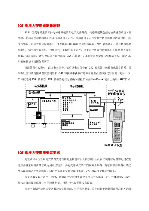
3051型压力变送器测量原理3051 型变送器主要部件为传感器模块和电子元件外壳。
传感器模块包括充油传感器系统(隔离膜、充油系统和传感器)以及传感器电子元件。
传感器电子元件安装在传感器模块内并包括一温度传感器(电阻式测试检测器)、储存模块和电容/数字信号转换器(C/D 转换器)。
来自传感器模块的电子信号被传输到电子元件外壳中的输出电子元件。
电子元件外壳包括输出电子线路板(微处理器、储存模块、数字/模拟信号转换器或D/A 转换器)、本机零点及量程按钮和端子块。
3051CD 型变送器基本简图如图所示。
当油偏离中心膜时,改变电容信号。
然后该电容信号在C/D 转换器中被转换成数字信号。
随后微处理器从电阻式温度检测器和C/D 转换器中获取信号并计算出正确的变送器输出。
随后,该信号被送到D/A 转换器,D/A 转换器将信号转换回模拟信号并在4-20 mA 输出上叠加HART信号。
3051型压力变送器安装要求变送器和引压管线的安装对变送器的测量精度有很大的影响,因此在安装时应尽量靠近过程的地点并且采用最少的管线达到最佳精度。
并将变送器安装牢固以防止倾斜,变送器本体倾斜可导致变送器输出产生零点漂移。
同时变送器的安装应确保振动、冲击和温度变化达到最低。
当变送器安装在法兰一侧时,共面法兰定位时要确保正常排气或排液。
对于气体测量,排液/排气装置连接在底部,对于液体测量,排液/排气装置连接在顶部。
在投产前期严禁通过变送器冲洗引压管线。
对于蒸汽测量,首先应将变送器隔离然后再冲洗管线,在恢复测量前将管线再用水充满。
3051型压力变送器性能指标输出2 线4-20 mA,用户可选择线性或平方根输出。
数字过程变量可叠加在4-20 mA 信号上,任何符合HART 协议的主机都可使用。
电源需要外部电源。
标准变送器(4-20 mA)可在无负载情况下在电压达到10.5 至55 V dc 时运行。
最大负载最大回路电阻取决于外部电源的电压水平,最大回路电阻= 43.5参考精度±0.075% 量程阻尼对于阶式信号输入变化的模拟输出响应,用户可从0 到25.6 秒之间选择一时间常数。
溅射薄膜压力传感器芯体 ver1 胡汉
外形结构与安装尺寸(单位:mm) 应变芯体结构图(¢7 mm)
X-Mag
新磁(上海)电子有限公司
上图为薄膜应变芯体结构图,其上表面为应变区域,下端为引压孔。
选型指南
代码 名称
GkB
溅射薄膜敏感元件
J
军用
M
民用
代码 桥路(可选)
1
开桥
2
闭桥
代码 补偿(可选)
A
不带 RE
B
带 RE
代码 焊接(可选)
1
X-Mag
新磁(上海)电子有限公司
溅射薄膜压力传感器芯体/敏感元件
产品概述 溅射薄膜敏感芯体采用离子束溅射技术将纳米薄膜应变电阻直接与金属弹性体紧密结合在陶瓷绝缘膜上,实现
了金属弹性体和绝缘膜的原子结合,具有耐腐蚀、抗振动、测量范围宽、测量精度高等特点。压力敏感元件通过与 压力接头焊接、敏感电阻引线焊接后,再进行参数补偿、信号调理、壳体封装等即可组装成满足不同压力和外形尺 寸的各种压力传感器。
产品特点
• 采用溅射工艺
• 长期稳定性好
• 激光调阻补偿零点和温度性能
• 输出信号线性化
• 宽量程,体积小型化
• 可实现智能化,数字化
性能指标
技术参数
规格
测量范围
1、2、3、7、10、20、30、40、60、100、150、200MPa
允许过载
200%FS
激励电压
0~15VDC
输入阻抗
2.9~4.3KΩ
压焊
2
锡焊
代码 工作温度(可选)
C
常温(-30℃~80℃)
D
高温(-40℃~125℃)
E
高温(-70℃~280℃)
Ceracore USC30 压力传感器说明书
Products Solutions Services TI01650OEN715413262022-07-19Technical InformationCeracore USC30Process pressure measurementCapacitive, ceramic pressure sensorApplicationPressure sensor for use in the pressure measurement of liquid and gaseous media.Your benefitsDry capacitive ceramic sensor with ultrapure (99.9%) Al2O3 ceramic•High overload resistance•Very good long-term stability•High corrosion resistance•Digital/analog signal output (SPI, UART, U)•Small physical size•Measuring ranges from 0 to 0.1bar (0 to 1.5psi) to0 to 100bar (0 to 1500psi)•Optional temperature output, switch outputCeracore USC302Endress+HauserTable of contentsAbout this document . . . . . . . . . . . . . . . . . . . . . . . . . . . .3Document function . . . . . . . . . . . . . . . . . . . . . . . . . . . . . . . . . . . . 3Symbols used . . . . . . . . . . . . . . . . . . . . . . . . . . . . . . . . . . . . . . . . . 3Function and system design . . . . . . . . . . . . . . . . . . . . . .4Measuring principle . . . . . . . . . . . . . . . . . . . . . . . . . . . . . . . . . . . 4CARMEN . . . . . . . . . . . . . . . . . . . . . . . . . . . . . . . . . . . . . . . . . . . . . 4Input . . . . . . . . . . . . . . . . . . . . . . . . . . . . . . . . . . . . . . . . . .5Measured process variable . . . . . . . . . . . . . . . . . . . . . . . . . . . . . . 5Measuring range . . . . . . . . . . . . . . . . . . . . . . . . . . . . . . . . . . . . . . 5Power supply . . . . . . . . . . . . . . . . . . . . . . . . . . . . . . . . . . .6Supply voltage . . . . . . . . . . . . . . . . . . . . . . . . . . . . . . . . . . . . . . . . 6Current consumption . . . . . . . . . . . . . . . . . . . . . . . . . . . . . . . . . . 6Sensor connection . . . . . . . . . . . . . . . . . . . . . . . . . . . . . . . . . . . . . 6Output. . . . . . . . . . . . . . . . . . . . . . . . . . . . . . . . . . . . . . . . .7Output signal . . . . . . . . . . . . . . . . . . . . . . . . . . . . . . . . . . . . . . . . . 7Signal range and signal on alarm of voltage output . . . . . . . . . 7Behavior in the event of an error . . . . . . . . . . . . . . . . . . . . . . . . . 7Dead time, time constant . . . . . . . . . . . . . . . . . . . . . . . . . . . . . . . 7Dynamic behavior . . . . . . . . . . . . . . . . . . . . . . . . . . . . . . . . . . . . . 8Damping . . . . . . . . . . . . . . . . . . . . . . . . . . . . . . . . . . . . . . . . . . . . . 8Noise filter . . . . . . . . . . . . . . . . . . . . . . . . . . . . . . . . . . . . . . . . . . . 8Switch-on time and Warm-up period . . . . . . . . . . . . . . . . . . . . . 8Performance characteristics . . . . . . . . . . . . . . . . . . . . . .9Reference operating conditions . . . . . . . . . . . . . . . . . . . . . . . . . . 9Reference accuracy . . . . . . . . . . . . . . . . . . . . . . . . . . . . . . . . . . . . 9Long-term stability . . . . . . . . . . . . . . . . . . . . . . . . . . . . . . . . . . . . 9Total Error Band (TEB) . . . . . . . . . . . . . . . . . . . . . . . . . . . . . . . . . 9Long-term stability . . . . . . . . . . . . . . . . . . . . . . . . . . . . . . . . . . . 11Installation. . . . . . . . . . . . . . . . . . . . . . . . . . . . . . . . . . . 11Influence of the installation position . . . . . . . . . . . . . . . . . . . . 11Installation conditions . . . . . . . . . . . . . . . . . . . . . . . . . . . . . . . . 11Process and ambient temperature . . . . . . . . . . . . . . . 11Process temperature range . . . . . . . . . . . . . . . . . . . . . . . . . . . . . 11Ambient temperature range . . . . . . . . . . . . . . . . . . . . . . . . . . . 11Storage temperature range . . . . . . . . . . . . . . . . . . . . . . . . . . . . 11Climate class . . . . . . . . . . . . . . . . . . . . . . . . . . . . . . . . . . . . . . . . . 11Electromagnetic compatibility (EMC) . . . . . . . . . . . . . . . . . . . . 11Overvoltage protection . . . . . . . . . . . . . . . . . . . . . . . . . . . . . . . . 11Safety notes . . . . . . . . . . . . . . . . . . . . . . . . . . . . . . . . . . . . . . . . . 11Mechanical construction . . . . . . . . . . . . . . . . . . . . . . . 12Device dimensions . . . . . . . . . . . . . . . . . . . . . . . . . . . . . . . . . . . . 12Materials . . . . . . . . . . . . . . . . . . . . . . . . . . . . . . . . . . . . . . . . . . . . 13Certificates and approvals. . . . . . . . . . . . . . . . . . . . . . 13RoHS . . . . . . . . . . . . . . . . . . . . . . . . . . . . . . . . . . . . . . . . . . . . . . . 13Other standards and guidelines . . . . . . . . . . . . . . . . . . . . . . . . . 13Calibration; unit . . . . . . . . . . . . . . . . . . . . . . . . . . . . . . . . . . . . . . 13Ordering information. . . . . . . . . . . . . . . . . . . . . . . . . . 14Disposal. . . . . . . . . . . . . . . . . . . . . . . . . . . . . . . . . . . . . . 14Accessories. . . . . . . . . . . . . . . . . . . . . . . . . . . . . . . . . . . 15Contact addresses . . . . . . . . . . . . . . . . . . . . . . . . . . . . . 15Explanations and supplementary documentation. . 16Terms and abbreviations . . . . . . . . . . . . . . . . . . . . . . . . . . . . . . 16Turn down calculation . . . . . . . . . . . . . . . . . . . . . . . . . . . . . . . . 17Supplementary documentation . . . . . . . . . . . . . . . . . . . . . . . . . 17CARMEN sensor settings . . . . . . . . . . . . . . . . . . . . . . . . . . . . . . 17Ceracore USC30Endress+Hauser 3About this documentDocument functionThis document contains all the technical data for the device and provides an overview of the device versions and accessories that can be ordered.Symbols usedSafety symbolsSymbols for certain types of informationSymbols in graphicsSymbolMeaning 1, 2, 3, …Item numbers A, B, C, …ViewsCeracore USC304Endress+HauserFunction and system designMeasuring principleA capacitive ceramic sensor element is at the core of the USC30. The basic material is (Al 2O 3), an ultra-pure (99.9%) aluminum oxide ceramic that is highly resistant to many aggressive gases and liquids. Two cylindrical ceramic components (process isolating diaphragm and ceramic substrate) are hermetically sealed together. In the case of absolute pressure sensors, the reference vacuum of3.0x 10-6mbar that is generated in the production process between the process isolating diaphragm and the ceramic substrate becomes permanent, thereby enabling precise pressure measurement relative to the vacuum. In the case of gauge pressure sensors, the back of the process isolating diaphragm is ventilated, i.e. this sensor measures the gauge pressure relative to the atmospheric pressure.In electrical terms, the sensor element represents a plate capacitor whose change in capacitance is a measure for the change in pressure. The capacitive measurement method satisfies the highestrequirements with regard to resolution and reproducibility. Together with the hysteresis-free behavior of the Al 2O 3 material, it forms the basis for the excellent technical specifications of the pressure sensor. Furthermore, the sensor element is a dry measuring cell, i.e. there is no separating diaphragm or oil filling which could influence the measurement. Another advantage of the capacitive ceramic sensor is its high overload resistance.A Gauge pressure cellB Absolute pressure cell 1Cr electrode 2Cp electrode3Brazing ring preform 4Counterelectrode 5Ceramic substrate6Process isolating diaphragm p Process pressurepatm Atmospheric pressureCARMENThe CARMEN ASIC is used in sensor applications to measure physical variables (e.g. pressure) with external capacitive or resistive sensors in industrial environments.Each sensor has its individual properties. CARMEN compensates for these physical properties individually. To do so, CARMEN performs the following steps:•Measurement of the external sensor (capacitance difference, voltage difference, temperature)•Compensation of the sensor offset •Gain adjustment•Linearization of the sensor characteristics •Compensation of temperature effects•Output of the corrected and compensated measured values •Additional functions (damping, filtering, etc.)For the standard settings of the sensor, →ä17.The functionality and communication are explained in the S&C CARMEN Manual.Ceracore USC30Endress+Hauser 5InputMeasured process variable•Gauge pressure or absolute pressure •TemperatureMeasuring rangeWARNING!The maximum pressure for the measuring device depends on the lowest-rated element with regard to pressure.‣The measuring device must be operated only within the specified limits!SensorMaximumsensor measuring range Lowest calibratable spanMWPOPLVacuum resistancelower (LRL)upper (URL)[bar (psi)][bar (psi)][bar (psi)][bar (psi)][bar (psi)][bar (psi)][bar abs (psi abs )]Sensors for gauge pressure measurement 0.1 (1.5)-0.1 (-1.5)+0.1 (+1.5)0.02 (0.3) 2.7 (40.5) 4 (60)0.7 (10.5)0.2 (3)-0.2 (-3)+0.2 (+3)0.04 (0.6) 3.3 (49.5) 5 (75)00.4 (6)-0.4 (-6)+0.4 (+6)0.08 (1.2) 4 (60) 6 (90)01 (15)-1 (-15)+1 (+15)0.2 (3) 6.7 (100.5)10 (150)02 (30)-1 (-15)+2 (+30)0.4 (6)12 (180)18 (270)04 (60)-1 (-15)+4 (+60)0.8 (12)16.7 (250.5)25 (375)010 (150)-1 (-15)+10 (+150) 2 (30)26.7 (400.5)40 (600)020 (300)-1 (-15)+20 (+300) 4 (60)26.7 (400.5)40 (600)040 (600)-1 (-15)+40 (+600)8 (120)40 (600)60 (900)0100 (1500)-1 (-15)+100 (+1500)20 (300)100 (1500)150 (2250)Sensors for absolute pressure measurement 0.1 (1.5)0+0.1 (+1.5)0.02 (0.3) 2.7 (40.5) 4 (60)00.2 (3)0+0.2 (+3)0.04 (0.6) 3.3 (49.5) 5 (75)00.4 (6)0+0.4 (+6)0.08 (1.2) 4 (60) 6 (90)01 (15)0+1 (+15)0.2 (3) 6.7 (100.5)10 (150)02 (30)0+2 (+30)0.4 (6)12 (180)18 (270)04 (60)0+4 (+60)0.8 (12)16.7 (250.5)25 (375)010 (150)0+10 (+150) 2 (30)26.7 (400.5)40 (600)020 (300)0+20 (+300) 4 (60)26.7 (400.5)40 (600)040 (600)0+40 (+600)8 (120)40 (600)60 (900)0100 (1500)+100 (+1500)20 (300)100 (1500)150 (2250)Ceracore USC306Endress+HauserPower supplySupply voltageCurrent consumption < 1.6mASensor connectionIncorrect polarity can damage the ASIC!‣Ensure polarity is correct.Incorrect analog measured value due to cable break from GND!‣Prevent cable break from GND.Female header strip 2x5 pins (1.27mm (0.05in) spacing)•Socket type: SAMTEC SFML-105-02-L-D •Insertion force (axial only): max.40NTypeValue Digital output, Analog output2.9 … 5.5V DCPIN Designation Explanation Application Digital AnalogUARTSPI 1GND Negative supply voltage X X X 2RESET_N Reset (low active)optional optional optional 3VDD Positive supply voltageX X X 4DAC Analog output (Digital to analog converter)optional optional optional 5SW_OUT Switch output (open drain)optional optional optional 6SPI_SEL Communication mode selection (UART "GND" or SPI "VDD")force to "GND"force to "VDD"force to "GND"7SCK SPI clock, must be connected to GND if SPI is not used –X –8CS_N Chip select (low active)optional optional –9TxD/SO_RDY Digital communication outputX X –10RxD/SIDigital communication input, must be connected to GND if not usedXXforce to "GND"Ceracore USC30Endress+Hauser 7OutputOutput signalSignal range and signal onalarm of voltage output1Calibrated measuring range 2Extended measuring range DAC Digital-to-analog converterThe signal range and the signal on alarm are based on NAMUR NE 43. The error value of the signal on alarm can be configured and is displayed in the illustration for the example >95%VDD (CARMEN standard sensor setting).Behavior in the event of an errorSee the S&C CARMEN ManualDead time, time constantPresentation of the dead time and the time constant:TypeOutputVoltage output (pressure) 1)1)Max. load: min. 1M Ω, max. 1nF10 to 90% VDD (ratiometric, VDD = 5.0V DC)10 to 90% VDDA (absolut, VDDA = 2.65V DC)Digital output (pressure & temperature)SPI UARTSwitch output (pressure) 2)2) On requestSwitch (via CARMEN)Ceracore USC308Endress+Hauser1% of the measured valuet timeDynamic behaviorDamping Customizable setting: 0 to 40sNoise filter A noise filter is optionally available as a sensor add-on function (see S&C CARMEN Customer Manual).Switch-on time and Warm-up periodThe switch-on time is the time that elapses from when the supply voltage is switched on to when the first digital value or initial analog value is available.The warm-up period is the time that elapses from when the supply voltage is switched on to the first digital measured value or analog value within the specified reference accuracy (e.g. 0.1% span).Output Sampling rate [ms]Dead time (t 1) [ms]Time constant T63 (t 2) [ms]Time constant T90 (t 3) [ms]Time constant T99 (t 4) [ms]Digital204074889951018.522251.25 1)3.75678Analog20296375885815.519221.2524.568.51)The maximum sampling rate that can be configured for measured value recording is 1.25ms, but the maximum speed of the digital output is limi-ted to 2.5ms.Output Sampling rate [ms]Switch-on time [ms]Warm-up period [ms]Digital2038.7598.75523.7538.751.252023.75Analog201050510351.251030Ceracore USC30Endress+Hauser 9Performance characteristicsReference operating conditions•As per DIN EN IEC 62828•Ambient temperature T A = constant, in range: +23 to +27°C (+73 to +81°F)•Relative humidity ϕ = constant, in range: 5 to 80% RH.•Ambient pressure p A = constant, in range: 860 to 1 060mbar (12.47 to 15.37psi)•Position of measuring cell = constant, in range: process isolating diaphragm pointing downwards (see also the "Influence of installation position" section →ä11)•Analog output supply voltage: 4.9 to 5.1V DC •Digital output supply voltage: 2.9 to 5.5V DC•Reference installation of Endress+Hauser (Components and Mounting instructions SD02471P)Reference accuracyThe reference accuracy includes the terminal-based non-linearity, the non-repeatability and the pressure hysteresis according to [DIN EN IEC 62828-1].Long-term stability ≤0.1%/year related to the upper range limit (URL).Total Error Band (TEB)The Total Error Band includes the following influencing factors:Sensor Reference accuracy in % of calibrated span Platinum ±0.1 x TD for TD 1) 1:1 to TD 5:11)TD = Turn Down, →ä17.Ceracore USC3010Endress+HauserTotal Error Band•Sensor measuring range: 0.1to 0.4bar •Process temperature: -20to 80°CTotal Error Band•Sensor measuring range: 1to 40bar •Process temperature: -20to 80°CError in % of the calibrated spanTemperature range Typ. value Max. value 0to +60°C (+32to +140°F)±0.15x TD ±0.30x TD –20+60to to 0°C +80°C(–4(+140to to +32°F)+176°F)±0.25x TD±0.50x TDError in % of the calibrated spanTemperature range Typ. value Max. value 0to +60°C (+32to +140°F)±0.10x TD ±0.20x TD –20+60to to 0°C +80°C(–4(+140to to +32°F)+176°F)±0.15x TD±0.30x TDCeracore USC30Endress+Hauser 11Long-term stability ≤0.1%/year related to the upper range limit (URL).InstallationInfluence of the installation positionAny installation position is possible but it may cause a zero point shift.Installation conditions•During installation, electrical connection and operation, no moisture may penetrate the device.•The back of the sensor element must not be encapsulated.Process and ambient temperatureProcess temperature range–40 to +125°C (–40 to +257°F)Compensated range –20 to +80°C (–4 to 176°F)Ambient temperature range–40 to +125°C (–40 to +257°F)Compensated range –20 to +80°C (–4 to 176°F)Storage temperature range –40 to +125°C (–40 to +257°F)Climate classElectromagnetic compatibility (EMC)No specifications (open system)Overvoltage protection 6V DC (maximum voltage for CARMEN ASIC)Safety notesFor work on and with the device:Process isolating diaphragm pointing downwards (A)Process isolating diaphragm axis is horizontal (B)Process isolating diaphragm pointing upwards (C)<1bar (15psi)Reference position, no effect Up to +0.1mbar (0.0015psi)Up to +0.2mbar (0.0030psi)≥1bar (15psi)Reference position, no effect<0.1mbar (0.0015psi)Up to +0.1mbar (0.0015psi)System Climate class NoteOpenClass 3K3Air temperature: 5 to 40°C (41 to 104°F),relative humidity: 5 to 85%satisfied according to 60721-3-3 (condensation not permitted)Ceracore USC3012Endress+HauserMechanical constructionDevice dimensionsSensor [bar (psi)]Y [mm]Z [mm]0.1 (1.5) 5.1312.880.2 (3) 5.1612.910.4 (6) 5.1912.941 (15) 5.2412.992 (30) 5.313.054 (60) 5.3713.1210 (150) 5.5113.2620 (300) 5.6313.3840 (600) 5.7813.53100 (1500)6.1313.88Ceracore USC30Endress+Hauser 13Materials Materials in contact with processTSE free (Transmissible Spongiform Encephalopathy)The following applies to all device components in contact with the process:•They do not contain any materials derived from animals.•No additives or operating materials derived from animals are used in production or processing.Certificates and approvalsRoHSThe measuring system complies with the substance restrictions of the Restriction on Hazardous Substances Directive 2011/65/EU.Other standards and guidelinesThe applicable European guidelines and standards can be found in the relevant EU Declarations of Conformity. The following were also applied:DIN EN IEC 62828-1, 62828-2:Reference conditions and procedures for testing industrial and process measurement transmitters Part 1: General procedures for all types of transmitters Part 2: Specific procedures for pressure transmitters DIN 16086:Electrical pressure measuring instruments, pressure sensors, pressure transmitters, pressure measuring instruments, concepts, specifications on data sheets.Procedure for writing specifications in data sheets for electrical pressure measuring instruments, pressure sensors and pressure transmitters.EN 61010-1 (IEC 61010-1):Protection Measures for Electrical Equipment for Measurement, Control, Regulation and Laboratory EquipmentCalibration; unitComponent partMaterialProcess isolating diaphragm Al 2O 3 aluminium oxide ceramic FDA, ultra-pure 99.9% 1)1)The US Food & Drug Administration (FDA) has no objections to the use of ceramics made of aluminum oxide as a surface material in contact with foodstuffs. This declaration is based on the FDA certificates of our ceramic suppliers.Designation Nominal range; mbar Nominal range; bar Nominal range; psi Nominal range; Pa Nominal range; kPa Nominal range; MPa Nominal range; mmH 2O Nominal range; mH 2O Nominal range; inH 2O Nominal range; ftH 2O Nominal range; mmHgCeracore USC3014Endress+HauserOrdering informationDetailed ordering information is available from the following sources:In the Product Configurator on the Endress+Hauser website:Product Configurator - the tool for individual product configuration • Product-specific configuration data• Depending on the device: direct input of information specific to measuring point, such as measuring range•Automatic verification of exclusion criteriaDisposalAccording to the Directive 2012/19/EU on waste electrical and electronic equipment (WEEE), our products are marked with the depicted symbol in order to minimize the disposal of WEEE as unsorted municipal waste. Such products may not be disposed of as unsorted municipal waste and can bereturned to Endress+Hauser for disposal at conditions stipulated in our General Terms and Conditionsor as individually agreed.Ceracore USC30Endress+Hauser 15AccessoriesContact addressesInternet: E-mail: **********************************Designation Type NotesProcess temperature range Installation componentsL-ring See mounting instructions SD02471P position 1–40 to +80°C (–40 to +176°F)PTFE foil See mounting instructions SD02471P position 4–40 to +125°C (–40 to +257°F)Ceramic ring See mounting instructions SD02471P position 5–40 to +125°C (–40 to +257°F)Pressure ring See mounting instructions SD02471P position 6–40 to +80°C (–40 to +176°F)Thread ringSee mounting instructions SD02471P position 7–40 to +125°C (–40 to +257°F)O-ringFKM ––20 to +80°C (–4 to +176°F)FKM, FDA FDA21 CFR177.2600 USP Class VI 3A; BAM0 to +80°C (+32 to +176°F)EPDMFDA21 CFR177.2600 USP Class VI (up to +70 °C (+158 °F)) 3A DVGW (W270, W534), WRAS, ACS NSF61–20 to +80°C (–4 to +176°F)NBR––20 to +80 °C (–4 to +176 °F)CableAdapter cable for female header strip 2x5 pins (1.27mm spacing)Mating connector for SAMTEC––10 to +80°C (+14 to +176°F)Ceracore USC3016Endress+HauserExplanations and supplementary documentationTerms and abbreviationsItem Term/abbreviation Explanation1OPLThe OPL (over pressure limit = sensor overload limit) for the measuring device depends on the lowest-rated element, with regard to pressure, of the selected components, i.e. the process connection has to be taken into consideration in addition to the measuring cell. Also observe pressure-temperature dependency.The test pressure corresponds to the overload limit of the sensor (OPL =1.5x MWP) and may only be applied for a limited period of time so that no permanent damage occurs.2MWPThe MWP (maximum working pressure) for the sensors depends on the lowest-rated element, with regard to pressure, of the selected components, i.e. the process connection has to be taken into consideration in addition to the measuring cell. Also observe pressure-temperature dependency.The Pressure Equipment Directive (2014/68/EU) uses the abbreviation "PS", which corresponds to the MWP of the measuring instrument.The MWP refers to a reference temperature of +20°C (+68°F) and may be applied at the device for an unlimited period.3Maximum sensor measuring range Span between LRL and URLThis sensor measuring range is equivalent to the maximum calibratable/adjustable span.4Calibrated/adjusted span Span between LRV and URV Default setting: 0 to URLOther calibrated spans can be ordered as customized spans.–p Pressure–LRL Lower range limit –URL Upper range limit –LRV Lower range value –URV Upper range value–TD Turn DownExample - see the following section.–CARMEN C apacitive A nd R esistive M easurement EN dress+Hauser →ä4–Sampling rateThe sampling rate is the integration time for recording the measured value and also the update interval for the output of measured values.Exception: If a sampling rate of 1.25ms is configured, the integration time is 1.25ms but the update interval 2.5ms.–ASICApplication-specific integrated circuitCeracore USC30Endress+Hauser 17Turn down calculation1Calibrated/adjusted span 2Upper range limitFor TD <1, the performance characteristics of TD =1 apply.Supplementary documentation•Mounting instructions SD02471PCARMEN sensor settingsThe sensor setting is configurable, see S&C CARMEN Customer Manual.Example•Sensor: 10bar (150psi)•Upper range limit (URL) = 10bar (150psi)•Lower range limit (LRL) = -1bar (-15psi)•Calibrated/adjusted span:0 to 5bar (0 to 75psi)•Lower range value (LRV) = 0bar (0psi)•Upper range value (URV) = 5bar (75psi)Turn Down (TD):TD =URL | URV − LRV |TD =10bar (150psi)= 2|5bar (75psi)− 0bar (0psi) |In this example, the TD is 2:1.Default settings Measuring mode Continuous Damping0Analog initial value <5%Analog error value>95%Analog error behavior (status flags)0, 1, 2, 4, 5, 9, 10, 15, 17, 18Digital error behavior (status flags)0, 1, 2, 4, 5, 9, 10, 15, 17, 18UART baud rate57.6kBd Digital continuous transmission Activated Switching threshold, on 0%Switching threshold, off 0%Switching delay0sCeracore USC30 18Endress+HauserCeracore USC30Endress+Hauser1971541326 71436431。
罗斯蒙特3051压力变送器
经实践检验的压力测量行业领袖•一流性能,参考精度高达 0.065%•共面™平台支持集成压力、流量和液位方案•整个 HART 产品系列通过了 IEC 61508 SIL2 级安全认证,可在遵从法规的同时简化您的工作 •超过20年的向后兼容性使您在投资最新特性的同时不会增加工厂的复杂性•全球装机量超过 7 百万台罗斯蒙特 3051 压力变送器目录订购信息. . . . . . . . . . . . . . . . . . . . . . . . . . . . . . . . 第 2 页规格. . . . . . . . . . . . . . . . . . . . . . . . . . . . . . . . . . 第9 页产品认证. . . . . . . . . . . . . . . . . . . . . . . . . . . . . . . .第14 页尺寸图. . . . . . . . . . . . . . . . . . . . . . . . . . . . . . . . .第16页罗斯蒙特 3051D 共平面压力变送器其他信息规格:第9 页认证:第14 页尺寸图:第16 页表 1. 3051D 共平面压力变送器订购信息★ 标准产品表示最普通的选项。
为了实现快速交货,建议选择带星号的选项(★)。
对于扩展选项,交付周期需要另行商定。
型号变送器类型3051D共平面压力变送器测量类型标准标准P差压★G表压★压力范围3051DP3051DG标准标准1–6.22 kPa 至 6.22 kPa(–25 至 25 inH2O)–6.22 kPa 至 6.22 kPa(–25 至 25 inH2O)★2–62.2 kPa 至 62.2 kPa(–250 至 250 inH2O)–62.2 kPa 至 62.2 kPa(–250 至 250 inH2O)★3–248 kPa 至 248 kPa(–1000 至 1000 inH2O)–97.9 kPa 至 248 kPa(–393 至 1000 inH2O)★4–2070 kPa 至 2070 kPa(–300 至 300 psi)–97.9 kPa 至 2070 kPa(–14.2 至 300 psi)★5–13800 kPa 至 13800 kPa(–2000 至 2000 psi)–97.9 kPa 至 13790 kPa(–14.2 至 2000 psi)★变送器输出标准标准A(1)4–20 mA,采用基于HART协议的数字信号★结构材料工艺法兰类型法兰材料排放/排气阀标准标准2共平面式316 不锈钢316 不锈钢★3(2)共平面式铸铁 C-276 合金 C-276★6共平面式304 不锈钢316 不锈钢★7(2)共平面式316 不锈钢合金 C-276★0备选工艺连接★3051D 共平面压力变送器2表 1. 3051D 共平面压力变送器订购信息★ 标准产品表示最普通的选项。
XSR22FCK-ALKRIB1B1V0使用说明书
XSR22FCK-ALKRIB1B1V0使用说明书专业资料工程科技机XSR22FCK-ALKRIB1B1V0使用说明书XSR22FC补偿流量积算记录仪XSR22FCK-ALKRIB1B1V0用户手册XSR22FC广州纹徕仪器仪表安全注意请务必遵守下述各条及本产品说明书所记载的注意事项。
如果不遵守注意事项进行使用,有导致重大伤害或事故的危险。
●t请不要使用在原子能设备、医疗器械等与生命相关的设备上。
●t本仪表没有电源保险丝,请在本仪表电源供电回路中设置保险丝等安全断路器件。
●t请不要在本产品所提供的规格范围之外使用。
●t请不要使用在易燃易爆的场所。
●t请避免安装在发热量大的仪表(加热器、变压器、大功率电阻)的正上方。
●t周围温度为50℃以上时,请用强制风扇或冷却机冷却,但是,不要让冷却空气直接吹到本仪表。
●t对于盘装仪表,为了避免用户接近电源端子等高压部分,请在最终设备上采取必要措施。
●t本产品的安装、调试、维护应由具备资质的工程技术人员进行。
●t如果本产品的故障或异常有可能导致系统重大事故,请在外部设置适当的保护电路,以防止事故发生。
●t本公司不承担除产品本身以外的任何直接或间接损失。
本公司保留未经通知即更改产品说明书的权利。
18、型号规格内容代码及说明XSR22FC外形尺寸A160(W)×80(H)×65(L)流量输入信号I电流:(4~20)mADC、(0~10)mADC或(0~20)mADCV 电压:(0~5)VDC、(1~5)VDCMmV(订货注明量程范围)K脉冲温度输入信号(没有则不填)R热电阻PT100、CU100、CU50压力输入信号(没有则不填)I直流电流(4-20mA、0-10mA、0-20mA)V直流电压(1-5V、0-5V)M直流毫伏(订货注明量程范围)报警点数量TT0 ~T2:表示无报警点到2点报警变送输出A0无变送输出A1电流输出(4-20mA、0-10mA、0-20mA)A2电压输出(1-5V、0-5V)A3电压输出(0-10V)A4其他输出外供电源(压力通道供电)B0无外供电源B1外供24VDC,误差小于±5%,50mAB2外供12VDC,误差小于±5%,50mA 外供电源(流量通道供电)B0无外供电源B1外供24VDC,误差小于±5%,50mAB2外供12VDC,误差小于±5%,50mA通讯接口S0无通讯接口S1RS232接口(公司标准协议)S2RS485接口(公司标准协议)M1RS232接口(MODBUS-RTU协议)M2RS485接口(MODBUS-RTU协议)仪表电源V085~265V ACUSB转储接口USB不带可省略非标准功能N19、技术规格19.1 输入◆ 温度显示范围:-999.9~999.9◆ 瞬时流量、压力显示范围:-99999~99999,小数点位置可设定◆ 累积流量显示范围:0~1000000000,小数点位置可设定◆ 输入信号类型:流量:1~5V DC,0~5V DC,4~20mA,0~10mA,0~20mA,3~5000 Hz脉冲(脉冲信号幅值必须大于5V)温度:无温度、固定温度、Pt100,Cu100,Cu50可通过设定选择压力:无压力、固定压力、1~5V DC,0~5V DC,4~20mA,0~10mA,0~20mA其它输入信号或分度号需在订货时注明◆ 基本误差:模拟量小于±0.2%F.S◆ 测量分辨力:160000,16位AD转换器◆ 测量控制周期:每通道0.2秒19.2 记录◆ 记录容量:4MBit◆ 记录间隔:1秒~59分59秒任意设定,可选择循环或非循环记录◆ 记录时间:记录时间的长短和记录间隔有关,计算公式如下:记录小时数= 12 × 记录间隔(秒)◆ 由此可以算出记录最短时间为24小时,最长时间为9年19.3 报警◆ 可通过设定选择瞬时流量、温度、压力上下限报警方式或累积量预置输出方式◆ 继电器输出:触点容量220V AC,3A19.4 变送◆ 光电隔离◆ 4~20mA,0~10mA,0~20mA直流电流输出,通过设定选择。
- 1、下载文档前请自行甄别文档内容的完整性,平台不提供额外的编辑、内容补充、找答案等附加服务。
- 2、"仅部分预览"的文档,不可在线预览部分如存在完整性等问题,可反馈申请退款(可完整预览的文档不适用该条件!)。
- 3、如文档侵犯您的权益,请联系客服反馈,我们会尽快为您处理(人工客服工作时间:9:00-18:30)。
产品名称:佛山山明862共面法兰微压变送器/微压压力传感器
862系列共面法兰微差压变送器,可以选择分别测量干净气体和液体/脏气体的两种微差压传感器。
其中干式传感器
的最小量程可达0~10Pa。
任意安装对零点无影响。
湿式传感器可以测量液体,以及结垢和腐蚀的脏气体。
无断点温度和线性修正技术使出厂标称指标和现场运行精度更加接近。
862系列系列共面法兰差压变送器采用规模可变设计。
有本安和隔爆两种外壳,各种传感器/电子部件有数十种组合。
在保证可靠性的前提下,按精度/材质/通讯定义了四种性能级别。
以满足不同应用对价格和性能的需求。
其中,862-4是低成本产品,而862-10采用了差压/压力/温度同时测量和补偿的复合式传感器
产品特色
●可选干/湿两种微差压传感器
●最小量程可达0 ~10Pa
●任意安装对零点无影响
●从低成本到高性能四种性能级别
●标配LCD和隔离式磁键
技术参数:
指标
型号
862-4 862-6 862-9 862-10
精度
<=100Pa
2% 1% 0.5% 0.5%
精度>100Pa 0.25% 0.1% 0.075% 0.075%
静压影响0.1% 0.1% 0.1% 0.05%
量程比10:1 30:1 120:1 120:1
补偿方式五点温
补八点温补无断点温补无断点温补
和静压补偿
输出信号两线制
4~20mA 两线4~20mA 两线制4~20mA
HART协议
两线制4~20mA
HART协议或
MODBUS 协议
法兰材质碳钢镀
镍
碳钢镀镍316L不锈钢316L不锈钢
传感器材质:干式传感器:硅/玻璃;湿式传感器:316L不锈钢
最大静压::干式传感器:200KPa;湿式传感器:7MPa
单端过载:干式传感器:100KPa;湿式传感器:7MPa
长期稳定性:+-0.1%FS/年;环境温度:-20~70℃;相对湿度:0~100%RH
隔离膜片:316L不锈钢、哈氏合金C-276、钽;灌充液:硅油、氟油
外壳材质:铸铝、环氧树脂喷涂、丁晴橡胶O型环;防护等级:IP67
防暴认证:本质安全ExiaⅡCT4;隔离防暴ExdⅡCT6;电源影响:+/-0.005%/V 启动时间:取决于量程及量程比:0.1~106秒;供电:15~45V
阻尼:0~32秒可调;迟滞:0.05%;刷新速率: 22次/秒
抗冲击:加速度:50g;持续时间:11ms;电磁兼容性:ICE61000-4-2~5
负载:工作状态:0~1290Ω;数字通讯:250~600Ω;按键:外置隔离磁键
电气连接:2个1/2-14NPT或M20x1.5接线孔,适合与截面积2.5mm?以下导线
显示:点阵式LCD同屏多参数显示,差压,电流,百分比
报警电流:最小报警电流3.6mA,最大报警电流21mA,可组态。