S750 G2连接网络基本操作2
S750G2 GIStar培训流程
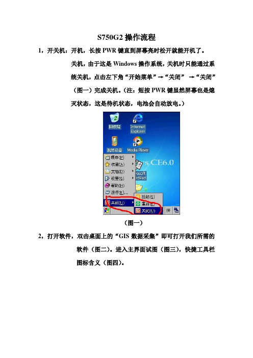
S750G2操作流程1,开关机:开机,长按PWR键直到屏幕亮时松开就能开机了。
关机,由于这是Windows操作系统,关机时只能通过系统关机,点击左下角“开始菜单”→“关闭”→“关闭”(图一)完成关机。
(注:短按PWR键虽然屏幕也是熄灭状态,这是待机状态,电池会自动放电。
)(图一)2,打开软件,双击桌面上的“GIS数据采集”即可打开我们所需的软件(图二)。
进入主界面试图(图三),快捷工具栏图标含义(图四)。
(图二)(图四)(图三)3,新建工程:点击“管理”→“工程”→“新建工程”(图五),“工程名称”后面输入工程的名称,点击“下一步”(图六),(图五)(图六)点击“编辑”对坐标系统进行设置(图七),点击“椭球”选项卡设置我们需要的坐标系(图八)。
(图七)(图八)点击“投影”选项卡输入我们当地的中央子午线(图九)。
如果我们还有“七参”“四参”“高程”“垂直”或“校正”参数的话,可以点击对应的选项卡输入。
最后在“名称”后面输入坐标系统的名称(建议最好和工程名称相同),都输入完成后点击“确定”(图十)回到坐标系统界面。
(图九)(图十)选择我们所编辑的坐标系统(图十一)点击“下一步”,进入记录条件界面,此界面下可以对“状态限制”“PDOP限制”“HRMS 限制”“VRMS限制”进行设置,其中“状态限制”必须选择“差分3D”(图十二),其他限制值越小越好(注:其他的限制条件一般情况下保持默认值就行)。
(图十一)(图十二)都设置好后点击“下一步”进行新建文件,在“文件名称”后面输入文件名称,一般用选用“手动命名”(图十三),(注:文件名称一般用当天的日期为好),输入完文件名称后点击“完成”完成工程的新建。
(图十三)4,GPS设置:点击“管理”→“GPS”→“基本设置”(图十四),在差分模式后面选择“SBAS”(图十五),→点击“SBAS设置”,在选择模式后面选择“定制的SBAS卫星”→点击“确定”→“确定”(图十四)(图十五)(图十六)再点击“管理”→“GPS”→“信息查看”(图十七),点击“测试”出现GPS端口调试界面,看接受后面是否有数据返回,如果有数据返回点击右上角的“X”号关闭就行,如果没有数据返回,点击左下角“关闭”再点击“打开”就会有数据返回的(图十八)。
1250gs 使用手册

1250gs 使用手册一、概述1250gs是一款高性能、高可靠性的工业级串口服务器,广泛应用于工业自动化、物联网、智能家居等领域。
本手册旨在为用户提供1250gs的使用指南,帮助用户正确、安全地使用该设备。
二、设备安装1.连接电源:将1250gs设备的电源线连接到合适的电源插座。
2.连接网络:将1250gs设备的网线连接到网络交换机或路由器。
3.设备连接:将1250gs设备的串口线连接到需要通信的设备。
三、设备配置1.登录设备:使用终端软件(如PuTTY)连接到1250gs 设备的串口,波特率设置为9600。
2.配置IP地址:在终端软件中输入“ipconfig”命令,查看设备的IP地址。
3.配置端口号:在终端软件中输入“set port”命令,设置需要通信的端口号。
4.配置波特率:在终端软件中输入“set baud”命令,设置波特率。
5.保存配置:在终端软件中输入“save”命令,保存配置信息。
四、设备使用1.数据发送:在终端软件中输入需要发送的数据,按回车键发送。
2.数据接收:在终端软件中输入“show data”命令,查看接收到的数据。
3.远程控制:通过网络访问1250gs设备的IP地址,实现对设备的远程控制。
4.故障排除:当设备出现故障时,可以通过终端软件查看错误信息,进行故障排除。
五、注意事项1.在使用过程中,请确保设备连接稳定可靠,避免出现断线或掉电等情况。
2.在配置过程中,请确保IP地址、端口号和波特率等参数设置正确,避免出现通信错误。
3.在使用远程控制功能时,请确保网络连接稳定可靠,避免出现网络故障导致控制失败。
4.在故障排除过程中,请仔细查看错误信息,根据错误信息进行相应的处理。
六、售后服务1.在购买后的一年内,如因产品质量问题导致设备损坏或无法正常使用,可享受免费维修或更换服务。
2.在使用过程中遇到任何问题,可随时联系我们的客服人员,我们将为您提供及时、有效的技术支持和服务。
水星MAC750R双频无线路由器上网怎样设置

水星MAC750R双频无线路由器上网怎样设置水星双频无线路由器上网设置方法1、登录设置界面:在浏览器的地址栏中输入melogin ,然后按下回车键浏览器中输入melogin2、在“设置密码〞框后面为路由器设置登录密码,在“确认密码〞中再次输入密码,点击“确认〞。
设置水星双频路由器的登录密码3、运行设置向导:登录到路由器的设置界面后,会自动弹出设置向导界面,如果没有弹出,可以点击左侧菜单中的“设置向导〞来运行。
运行水星双频路由器的设置向导4、选择上网方式:这里可以看到一共有4个选项,分别是:“让路由器自动选择上网方式(推荐)〞、“PPPoE(ADSL虚拟拨号)〞、“动态IP(以太网宽带,自动从效劳商获取IP地址)〞、“静态IP(以太网宽带,网络效劳商提供固定IP地址)〞。
水星双频路由器上的几种上网方式“让路由器自动选择上网方式(推荐)〞这个选项不建议大家选择,因为有的时候路由器识别不准确,会造成无法上网的;所以,最好是手动选择上网方式的。
(1)、PPPoE(ADSL虚拟拨号):目前,90%以上的用户办理的宽带都是“PPPoE(ADSL虚拟拨号)〞上网,办理“PPPoE(ADSL虚拟拨号)〞宽带业务后,宽带运营商会提供一个宽带用户名、宽带密码给用户;在未使用路由器时,需要通过电脑上的“宽带连接〞来拨号上网。
ADSL拨号上网设置:选择“PPPoE(ADSL虚拟拨号)〞——>点击“下一步〞水星双频路由器上选择ADSL上网方式输入宽带运营商提供的宽带帐号和密码——>点击“下一步〞。
设置ADSL的宽带用户名、宽带密码(2)、动态IP:也就是动态IP(DHCP获取IP),办理了“动态IP〞上网宽带业务的用户,宽带运营商会提供一根网线到用户家里;在未使用路由器时,只需要把这根网线插在电脑上,并把电脑的IP地址设置为自动获得,电脑就可以上网了。
动态IP设置:选择“动态IP(以太网宽带,自动从效劳商获取IP地址)〞——>点击“下一步〞水星双频路由器上选择动态IP上网方式(3)、静态IP:办理了“静态IP〞上网宽带业务的用户,宽带运营商会提供一根网线到用户家里,同时还会提供一个IP地址、子网掩码、网关、2个DNS效劳器地址给用户;在未使用路由器时,只需要把这根网线插在电脑上,并根据提供的IP地址信息来设置电脑上的IP地址。
南方S750手持GPS硬件操作及关键设置
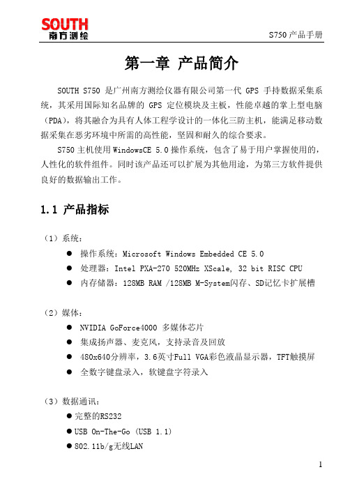
第一章产品简介SOUTH S750是广州南方测绘仪器有限公司第一代GPS手持数据采集系统,其采用国际知名品牌的GPS定位模块及主板,性能卓越的掌上型电脑(PDA),将其融合为具有人体工程学设计的一体化三防主机,能满足移动数据采集在恶劣环境中所需的高性能,坚固和耐久的综合要求。
S750主机使用WindowsCE 5.0操作系统,包含了易于用户掌握使用的,人性化的软件组件。
同时该产品还可以扩展为其他用途,为第三方软件提供良好的数据输出工作。
1.1 产品指标(1)系统:●操作系统:Microsoft Windows Embedded CE 5.0●处理器:Intel PXA-270 520MHz XScale, 32 bit RISC CPU●内存储器:128MB RAM /128MB M-System闪存、SD记忆卡扩展槽(2)媒体:●NVIDIA GoForce4000 多媒体芯片●集成扬声器、麦克风,支持录音及回放●480x640分辨率,3.6英寸Full VGA彩色液晶显示器,TFT触摸屏●全数字键盘录入,软键盘字符录入(3)数据通讯:●完整的RS232●USB On-The-Go (USB 1.1)●802.11b/g无线LAN●蓝牙1.2、Class II标准●内置GPRS/GSM通讯模块(选配)(4)GPS指标:●接收机:L1,C/A码,带载波相位平滑●通道:单频,12通道,并行跟踪(双通道SBAS跟踪)●重捕获时间:<1s●数据更新率:1Hz,可设置(最大20Hz)●冷启动:30s~45s●EVEREST多路径抑制技术(5)定位精度(典型值):●实时差分改正:亚米级(CEP)(外部源修正或SBAS)●后差分处理:亚米级(CEP)●静态:水平5mm+1ppm,高程10mm+1ppm(典型值要求最少能锁定5颗卫星,PDOP小于6,SNR最小值为39dBHz,且有合理的多路径条件等)(6)协议:●完全支持SBAS(MSAS\WAAS\EGNOS)●数据I/O,NMEA-0183(GGA、ZDA、GLL、RMC、GSA、GSV、VTG),TSIP●修正量I/O协议:RTCM2.3(1、3、9)(7)物理:●尺寸:284mm x 95mm x 37mm●重量:0.73kg(带电池)(8)电气:●电池:3.7V,2700mAh,可拆卸●在线充电:AC100-240~,0.5A,50-60Hz(9)工作环境:●湿度:5%~95% RH 非凝结状态●操作温度:-20摄氏度到+50摄氏度(-4华氏度到122华氏度)●存储温度:-40摄氏度到+60摄氏度(-40华氏度到140华氏度)●防水防尘等级IP65,完全保护从各个方向的冲水及扬尘,防震动及撞击1.2 产品特点介绍1、专业的GPS模块国际专业品牌测量型GPS天线及定位主板,采用最新的ASIC芯片和COAST专利算法,比导航型主板搜星更迅速稳定,定位更精确可靠。
南方测绘手持GPSS750G2培训手册PPT课件
10
1.7.1 电源设置
❖ 新机默认电源设置为省 电模式,一分钟后会自 动关机。用户可根据需 要对电源和背景进行设 置: 开始 设置 电源 (见右图)
1.7.2 电源设置
❖ 进入电源选项后,点击 上方“高级”,可根据 需要来设置设备自动关 闭时间的长短。 右图,如果单击方格, 去掉“×”,表示不用 自动关闭功能,这样仪 器便不会自动关机。
以校正参看参数如下:
点击保存
求取参数完毕
2.3 数据采集
一级菜单——状态
平面
(实时查看点位坐标信息)
按:ENT键两下瞬间采 集数据
确定后编辑采集点的元素 类型(点,线,面),以 及点号、天线高。
点击导航菜单
2.3 放样
点击导航—目标
1.5.2 与电脑的连接
如右图,安装好的同步 软件,当手持机连接电 脑后会自动运行。点击 “浏览”,即可进入数 据管理界面,可进行数 据下载、软件安装删除 等操作。
1.6 重启S750 G2主机
❖ 热启主机:请使用系统 内部软件功能。
❖ 冷启主机:用触笔,轻触 “复位关机键”,成功 关机后,再开机即可。
点增加 增加放样点
写在最后
成功的基础在于好的学习习惯
The foundation of success lies in good habits
32
谢谢聆听
·学习就是为了达到一定目的而努力去干, 是为一个目标去 战胜各种困难的过程,这个过程会充满压力、痛苦和挫折
Learning Is To Achieve A Certain Goal And Work Hard, Is A Process To Overcome Various Difficulties For A Goal
S7-1500网络配置步骤(内部培训)

S7-1500网络配置步骤(内部培训)S7-1500网络配置 (1)练习目的: (1)1.创建新项目并切换到项目视图 (2)2.添加PLC站点 (2)3. 网络视图中插入站点 (3)4.设置IP地址 (3)5.配置I/O模块 (4)6.分配设备名称 (5)7.下载程序 (5)培训人:培训对象:培训日期:练习目的:按照实际安装的硬件在TIA博途中进行配置,包括中央机架和PROFINET IO站点。
注意:由于初始的网络拓扑结构为环形,重新修改配置后可能造成网络故障,练习前需要将X208 P2端口的连接线拔出。
1.创建新项目并切换到项目视图2.添加PLC站点这里有两种选择:1:直接选择需要配置的CPU,然后配置I/O模块。
2:选择非指定的CPU,联机后通过CPU的识别功能自动上传中央机架上的模块。
注意:CPU的版本号。
如果选择“非指定的CPU”,在联机的情况下,点击“获取”按钮,系统自动检查中央机架上的模块。
S7-1500 CPU端口1缺省的IP地址为192.168.0.1,必须设置PC机的IP地址与CPU端口的IP地址在相同的网段。
3. 网络视图中插入站点在网络视图中分别插入ET200SP、ET200MP站点(分布式I/O目录)和ET200SP CPU站点(SIMATIC ET200 CPU目录)以及交换机X208(网络组件目录),使用鼠标拖放功能连接站点网络的接口,连接规则:先点击IO控制器的接口(例如CPU1511),然后拖放到IO设备的接口上(例如ET200MP的接口模块IM155-5),这样ET200SP、ET200MP站点、交换机X208将作为CPU1511的IO设备。
由于CPU1512 SP带有CPU,只能进行网络连接而不能分配从属关系(需要在设备属性中定义)。
4.设置IP地址点击站点的以太网接口,在属性窗口中分配IP地址和子网掩码。
CPU1511的IP地址为192.168.0.1;ET200MP的IP地址为192.168.0.2;ET200SP的IP地址为192.168.0.3;ET200SP CPU的IP地址为192.168.0.11;交换机X208的IP地址为192.168.0.22子网掩码为255.255.255.0.5.配置I/O模块进入设备视图,分别为各个站点配置I/O模块。
DL750高级网络和PC连接Web服务器功能说明书
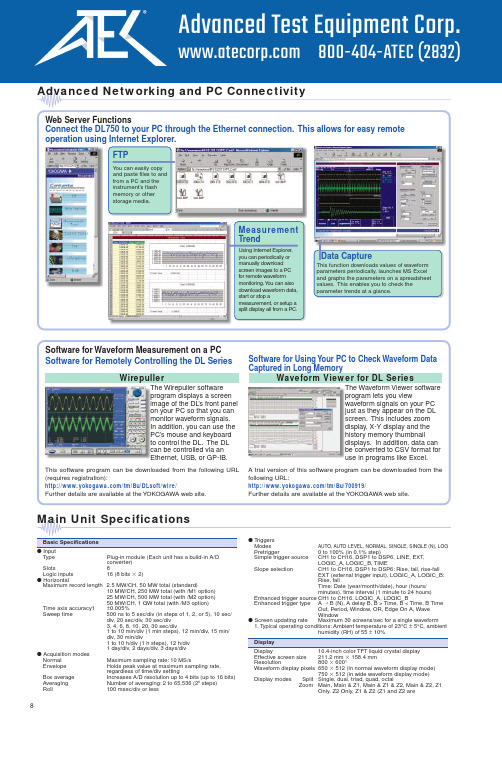
Advanced Networking and PC ConnectivityWeb Server FunctionsConnect the DL750 to your PC through the Ethernet connection. This allows for easy remote operation using Internet Explorer.FTPY ou can easily copyand paste files to andfrom a PC and theThe Wirepuller softwareprogram displays a screenimage of the DLon your PC so that you canmonitor waveform signals.In addition, you can use thePC’s mouse and keyboardHigh-Speed 10 MS/s 12-Bit Isolation Module (701250)Input channels2Input couplings AC, DC, GNDMaximum sampling rate10 MS/sA/D conversion resolution12 bits (150 LSB/div)Input type Isolated unbalancedFrequency range(–3 dB)1DC, up to 3 MHzInput range(10:1)50 mV/div to 200 V/div (in steps of 1, 2, or 5),(1:1) 5 mV/div to 20 V/div (in steps of 1, 2, or 5) Effective measurement range20 div (display range: 10 div)DC offset±5 divMaximum input voltage (1 kHz or less)In combination with 700929 (10:1) 2600 V (DC + ACpeak)Direct input (1:1) 6, 10250 V (DC + ACpeak)Maximum allowable in-phase voltageIn combination with 700929 (10:1) 3400 Vrms (CA T I), 300 Vrms (CA T II) In combination with 7019in steps of 1, 2, or 5+701954 (1:1) 9400 Vrms (CA T I), 300 Vrms (CA T II) Main unit only (1:1) 1142 V (DC + ACpeak) (CA T I and CAT II, 30 Vrms) DC accuracy1±(0.5% of 10 div)Input impedance 1 MΩ± 1%, approx. 35 pFConnector type Isolation type BNC connectorInput filter OFF, 500 Hz, 5 kHz, 50 kHz, 500 kHz Temperature coefficientZero point±(0.05% of 10 div)/°C (typical value)Gain±(0.02% of 10 div)/°C (typical value)High-Speed 1 MS/s 16-Bit Isolation Module (701251)Input channels2Input couplings AC, DC, GNDMaximum sampling rate 1 MS/sA/D conversion resolution16 bits (2400 LSB/div)Input type Isolated unbalancedFrequency range (–3 dB)1DC, up to 300 kHz (20 V/div to 5 mV/div)Input range(10:1)10 mV/div to 200 V/div (in steps of 1, 2, or 5)(1:1) 1 mV/div to 20 V/div (in steps of 1, 2, or 5) Maximum input voltage (1 kHz or less)In combination with 700929 (10:1) 2600 V (DC + ACpeak)Direct input (1:1) 6, 10140 V (DC + ACpeak)Maximum allowable in-phase voltageIn combination with 700929 (10:1) 3400 Vrms (CA T I), 300 Vrms (CA T II) In combination with 701901+701954 (1:1) 9400 Vrms (CA T I), 300 Vrms (CA T II)Main unit only (1:1) 1142 V (DC + ACpeak) (CA T I and CAT II, 30 Vrms) DC accuracy15 mV/div to 20 V/div±(0.25% of 10 div)2 mV/div±(0.3% of 10 div)1 mV/div±(0.5% of 10 div)Input impedance 1 MΩ± 1%, approx. 35 pFConnector type Isolated type BNC connectorInput filter OFF, 400 Hz, 4 kHz, 40 kHzTemperature coefficientZero point 5 mV/div to 20 V/div: ±(0.02% of 10 div)/°C (typical value)2 mV/div: ±(0.05% of 10 div)/°C (typical value)1 mV/div: ±(0.10% of 10 div)/°C (typical value)Gain 1 mV/div to 20 V/div: ±(0.02% of 10 div)/°C (typical value) High-Speed 10 MS/s 12-Bit Non-Isolation Module (701255)Input channels2Input couplings AC, DC, GNDMaximum sampling rate10 MS/sA/D conversion resolution12 bits (150 LSB/div)Input type Non-isolated unbalancedFrequency range (–3 dB)1DC, up to 3 MHzInput range(10:1)50 mV/div to 200 V/div (in steps of 1, 2, or 5)(1:1) 5 mV/div to 20 V/div (in steps of 1, 2, or 5) Effective measurement range20 div (display range 10 div)DC offset±5 divMaximum input voltage (1 kHz or less)In combination with 701940 (10:1)600 V (DC + ACpeak)Direct input (1:1)250 V (DC + ACpeak)DC accuracy1±(0.5% of 10 div)Input impedance 1 MΩ± 1%, approx. 35 pFConnector type Metal type BNC connectorInput filter OFF, 500 Hz, 5 kHz, 50 kHz, 500 kHz Temperature coefficientZero point±(0.05% of 10 div)/°C (typical value)Gain±(0.02% of 10 div)/°C (typical value)Adaptive passive probe (10:1)701940High-Voltage 100 kS/s 16-Bit Isolation Module (with RMS) (701260)Input channels2Input couplings AC, DC, GND, AC-RMS, DC-RMSMaximum sampling rate100 kS/sA/D conversion resolution16 bits (2400 LSB/div)Input type Isolated unbalancedFrequency range (–3 dB)1Waveform measurement modeDC, up to 40 kHzRMS measurement mode DC, 40 Hz to 10 kHzInput range(10:1)200 mV/div to 2000 V/div (in steps of 1, 2, or 5)(1:1)20 mV/div to 200 V/div (in steps of 1, 2, or 5) Effective measurement range20 div (display range 10 div)DC offset±5 divMaximum input voltage (1 kHz or less)In combination with 700929 (10:1) 21000 V (DC + ACpeak)In combination with 701901+701954 (1:1) 6850 V (DC + ACpeak)Maximum allowable in-phase voltageIn combination with 700929 (10:1)H side: 1000 Vrms (CAT II) 4, L side: 400 Vrms (CAT II) 5In combination with 701901+701954 (1:1)H side: 700 Vrms (CA T II) 7, L side: 400 Vrms (CA T II) 8Direct input (when using a cable which doesn’t comply with the safety standard)H/L sides: 30 Vrms (42 V DC + ACpeak)11 DC accuracy (waveform measurement mode)1±(0.25% of 10 div)DC accuracy (RMS measurement mode)1±(1.0% of 10 div)AC accuracy (RMS measurement mode)1Sine wave input±(1.5% of 10 div)Crest factor of 2 or less±(2.0% of 10 div)Crest factor of 3 or less±(3.0% of 10 div)Input impedance 1 MΩ± 1%, approx. 35 pFConnector type Isolated type BNC connectorInput filter OFF, 100 Hz, 1 kHz, 10 kHzT emperature coefficient (waveform measurement mode)Zero point±(0.02% of 10 div)/°C (typical value)Gain±(0.02% of 10 div)/°C (typical value) Response time (RMS mode)Rise (0 to 90% of 10 div)100 ms (typical)Fall (100 to 10% of 10 div)250 ms (typical)Crest factor (only at RMS measurement)3 or less*Please use 701901 (1:1 safety adaptor lead) or 700929 (10:1 safety probe), which complies with the safety standard, for high-voltage input.*It is very dangerous to use cables that do not comply with the safety standard.Temperature/High-Precision Voltage Module (701265)Input channels2Input couplings TC (thermocouple), DC, GNDInput type Isolated unbalancedApplicable sensors (input coupling: TC)K, E, J, T, L, U, N, R, S, B, W, iron-doped gold/chromel Data updating rate500 HzFrequency range (-3 dB)1DC, up to 100 HzVoltage accuracy1 (at voltage mode)±(0.08% of 10 div + 2 µV)T emperature measurement accuracy 1, 12Type Measured range AccuracyK–200°C to 1300°C±(0.1% of reading + 1.5°C)E–200°C to 800°C except –200 to 0°C:J–200°C to 1100°C±(0.2% of reading + 1.5°C) T–200°C to 400°CL–200°C to 900°CU–200°C to 400°CN0°C to 1300°CR, S0°C to 1700°C±(0.1% of reading + 3°C)except0 to 200°C: ±8°C200 to 800°C: ±5°C B0°C to 1800°C±(0.1% of reading + 2°C),except 400 to 700°C: ±8°CEffective range: 400 to 1800°C W0°C to 2300°C±(0.1% of reading + 3°C)Iron-doped gold/chromel0 to 300 K0 to 50 K: ±4 K50 to 300 K: ±2.5 KMaximum input voltage (1 kHz or less)42 V (DC + ACpeak) (CAT I and CA T II, 30 Vrms)Input range (for 10 div display)100 µV/div to 10 V/div (in steps of 1, 2, or 5) Input connector Binding postInput impedance Approx. 1 MΩInput filter OFF, 2 Hz, 8 Hz, 30 HzT emperature coefficient (for voltage)Zero point±((0.01% of 10 div)/°C + 0.05 µV)/°C (typical value)Gain±(0.02% of 10 div)/°C (typical value) Strain Module (NDIS) (701270)Input channels2Input types DC bridge input (automatic balancing), balanceddifferential input, DC amplifier (floating) Automatic balancing method Electronic auto-balanceAutomatic balancing range±10,000 µSTR (1 gauge method)Bridge voltages Select from 2 V, 5 V, or 10 VGauge resistances120 to 1000 Ω (bridge voltage of 2 V)350 to 1000 Ω (bridge voltage of 2/5/10 V) Gauge rate 1.90 to 2.20 (variable in steps of 0.01)A/D resolution16 bits (4800 LSB/div: Upper=ϩFS, Lower=–FS) Maximum sampling rate100 kS/sFrequency range (–3 dB)1DC, up to 20 kHzDC accuracy1±(0.5% of FS + 5 µSTR)Measurement range/measurable rangeMeasurement range (FS)Measurable range (–FS to +FS)500 µSTR–500 µSTR to 500 µSTR1000 µSTR–1000 µSTR to 1000 µSTR2000 µSTR–2000 µSTR to 2000 µSTR5000 µSTR–5000 µSTR to 5000 µSTR10,000 µSTR–10,000 µSTR to 10,000 µSTR20,000 µSTR–20,000 µSTR to 20,000 µSTRmV/V range support mV/V range = 0.5 ϫ (µSTR range/1000)Maximum allowable input voltage (1 kHz or less)10 V (DC + ACpeak)Maximum allowable in-phase voltage42 V (DC + ACpeak) (CAT I and CA T II, 30 Vrms)T emperature coefficientZero point±5 µSTR/°C (typical value)Gain±(0.02% of FS)/°C (typical value)Internal filter OFF, 1 kHz, 100 Hz, 10 HzInput connector NDIS standardAccessory (a set of connector shell for solder connection)2 NDIS connectors (A1002JC)Recommended bridge head (NDIS type) (sold separately)701955 (bridge resistance of 120 Ω) (w/ 5 m cable)701956 (bridge resistance of 350 Ω) (w/ 5 m cable)10Alligator clip (701954)Isolated probe (700929)Safety adaptor lead (701901)Earphone Mic (w/ PUSH switch) (701951)701280 Frequency Module■ Frequency Measurement SectionInput channels2Data update rate25 kHz (40 µs)Measurement range(frequency)0.01 Hz–200 kHz0.1 Hz/div–50 kHz/divHighest measurement resolution50 ns (20 MHz)■ Input SectionCompatible input signals Encoder pulse input of up to ±42 V,Electromagnetic pickup input 6AC power input up to 300 Vrms (700929 Isolation Probe required) Input type Isolated, unbalancedInput coupling AC,DCInput voltage (1:1)±1 V–±50 V (6 ranges, 1-2-5 steps)(10:1)±10 V–±500 V (6 ranges, 1-2-5 steps)Max input voltage (1 kHz or less)When combined with 700929 (10:1) 2420 V (DC+ACpeak)Direct input (1:1) 1042 V (DC+ACpeak)Max allowable common mode voltageWhen combined with 700929 (10:1) 3300 Vrms (CAT II)Direct input (1:1) 1142 V (DC+ACpeak) 30 Vrms (CAT II)Input impedance: 1 MΩ±1%, approx. 35 pFConnector type Isolated BNC connectorInput filters OFF/100 Hz/1 KHz/10 KHz/100 KHzInput pullup function (ON/OFF)Supports open collector, mechanical contact output, 4.7 KΩ(+5 V) Input chatter suppression (ON/OFF)Setting range 1 ms–1000 msComparator section Presets Logic (5 V/3 V/12 V/24 V), electromagnetic pickup, zero-cross,pullup (5 V), AC100 V, AC200 V, user-definedThreshold range±FS range, resolution in units of 1%Hysteresis±1%, ±2.5%, or ±5% of FSLED display (each CH)ACT (green)Operational status (illuminates during pulse input)OVER (red)Overdrive status (illuminates during an input overrange) Compatible probes/cables(10:1 probe) 700929/701940 (1:1 cable) 366926■ Measurement Function DetailsMeasurable items Frequency (Hz), rpm, rps, Period (sec), Duty (%), Power supplyfreq. (Hz), Pulse width (sec), Pulse integration, Velocity Effective measurement range20 div (10 div display range)Resolution of measured data16 bit (2400 LSB/div)Measurement items and rangesMeasured Item Measurement Range RangeFrequency (Hz)0.01 Hz–200 kHz0.1 Hz/div–50 kHz/divrpm0.01 rpm–100,000 rpm0.1 rpm/div–10,000 rpm/divrps0.001 rps–2000 rps0.01 rps/div–200 rps/divPeriod (sec) 5 µs–50 s10 µs/div–5 s/divDuty (%)0%–100%1%/div–20%/divPower supply freq (Hz)(50 Hz, 60 Hz, 400 Hz)±20 Hz0.1 Hz/div–2 Hz/divPulse width (sec) 2 µs–50 s10 µs/div–5 s/divPulse integration up to 2ϫ109 count100ϫ10-21/div–500ϫ1018/divVelocity Same as freq. (can be converted to km/h and other units) Auxiliary M easurement Functions■ Smoothing Filter Apply moving average to smooth stair step shaped waveforms.(moving average)Moving average constant is specified from 0.2 ms to 1000 msec(moving average constant=specified time ÷40 µs) This reduces jitterand increases the resolution.■ Pulse Average Function Measure the specified number of pulses at once, and specify 1 to4096 pulses for the average value output mode. This has the exactsame effect as the smoothing filter, but averaging can be performedat the pulse interval. Even if encoder gaps are unequal, you canmeasure pulses together and average them.■ Deceleration Prediction A measuring function that automatically compensates for the lack of (Braking Applications)encoder pulse information during deceleration and hypothesizes adeceleration curve.■ Stop Prediction Predicts stop from a specified time after pulse stop(Braking Applications)(set up to 10 stages).■ Offset Observation Function Set an observational center, then zoom and display surroundingarea (for fluctuation observation)Offset setting range = (1 div ϫ 1000)■ M easurement Accuracy 1 5■ Frequency/Revolution/Velocity MeasurementsM easurement accuracy±( 0.05% of 10 div + accuracy depending on the input frequency) Accuracy depending on the input frequency 1 Hz–2 kHz:0.05% of input waveform freq +1 mHz2 kHz–10 kHz:0.1% of input waveform freq10 kHz–20 kHz0.3% of input waveform freq20 kHk–200 kHz0.5% of input waveform freq■ Period MeasurementM easurement accuracy±( 0.05% of 10 div + accuracy depending on the input period) Accuracy depending on the input period500 µs–50 s0.05% of input waveform interval100 µs–500 µs0.1% of input waveform interval50 µs–100 µs0.3% of input waveform interval5 µs–50 µs0.5% of input waveform interval + 0.1 µs■Duty MeasurementAccuracy depending on the input frequency0.1 Hz–1 kHz±0.1% of 100%1 kHz–10 kHz±0.2% of 100%10 kHz–50 kHz±1.0% of 100%50 kHz–100 kHz±2.0% of 100%100 kHz–200 kHz±4.0% of 100%■Pulse Width MeasurementM easurement accuracy±( 0.05 % of 10 div + accuracy depending on the input pulse width) Accuracy depending on the input pulse width500 µs–100 s0.05% of input waveform pulse width100 µs–500 µs0.1% of input waveform pulse width50 µs–100 µs0.3% of input waveform pulse width2 µs–50 µs0.5% of input waveform pulse width + 0.1 µs■Power Supply Frequency MeasurementM easurement accuracy Center freq. at 50, 60 Hz, accuracy of ±0.03 Hz, resolution of 0.01 HzCenter freq. at 400 Hz, accuracy of ±0.3 Hz, resolution of 0.01 Hz 1Under standard operating conditions: (temperature 23˚C±5˚C, humidity 55%±10% RH, warmup of at least 30 minutes, and after calibration.)5Given a minimum input of 0.2 Vpp. M easurement conditions:■During freq./Period measurement: 1 Vpp/1µs square wave input (range=±10 V, bandwidth=FULL,hysteresis=±1%)■During Duty/pulse width measurement: 1 Vpp/5 ns square wave input (range=±10 V, bandwidth=FULL, hysteresis=±1%)■During power supply frequency measurement: 90 Vrms sinewave input (range=AC100 V, BW=100 kHz)6Electromagnetic pickup: given output within 0.2 Vpp–42 Vpp. Minimum sensitivity=0.2 V (at 1:1), connected with 1:1 cable. For types that requires a power supply or terminal resistance, apply it to the sensor side 700929In combination with 700929HL3524HLBNC1110Direct input(With a cable which doesn’t comply with the safety standard)701275 Acceleration/Voltage Module (with AAF)Input channels2Input format Switchable between acceleration and voltage inputAAF (anti-aliasing filter) supports both acceleration and voltage Input coupling(AC coupling for acceleration) ACCL, (voltage) AC,DC,GND Max sampling rate100 kS/sA/D conversion resolution16-bit (2400 LSB/div)Input type Isolated, unbalancedFrequency band (-3 dB)1(acceleration) 0.4 Hz–40 kHz (voltage) DC–40 kHzAC coupling (-3 dB point)acceleration/voltage0.4 Hz or lessInput rangeFor acceleration (±5 V=X1 range)X0.1–X1–X100 (1-2-5 steps)For voltage (10:1)50 mV/div–100 V/div (1-2-5 steps) 12For voltage (1:1) 5 mV/div–10 V/div (1-2-5 steps) 12Effective measuring range20 div (10 div display range)DC offset±5 divMax input voltage (1 kHz or less) 1242 V (DC+ACpeak)Max allowable common mode voltage 1142 V (DC+ACpeak) 30 Vrms (CAT II)Accuracy 1For voltage (DC accuracy)±(0.25% of 10 div)For acceleration (AC accuracy)±(0.5% of 10 div) (at 1 kHz)Input impedance 1 MΩ±1%, approx. 35 pFConnector type Metal BNC connectorInput filters OFF/Auto (AAF)/4 kHz/400 Hz/40 HzAnti-aliasing filter (AAF)Cutoff frequency 13fc (cutoff frequency)=fs (sampling frequency) ϫ 40%fc automatically moves to the sampling frequency.Cutoff characteristics-65dB at 2Xfc (Typical)Temperature coefficient (for voltage) 14Zero point±( 0.02% of 10 div )/ ˚C (Typical)Gain±( 0.02% of 10 div )/ ˚C (Typical)Acceleration sensor bias constant current drive =4 mA±10%, voltage < 22 VExample of compatible acceleration sensor: 15Built-in amp type: Kistler Piezotron™, PCB ICP™, Endevco: Isotron2™Something that supports acceleration sensor and bias is 4 mA/22 V Sensor usage Notes:The sensor is highly sensitive to heat and shocks. If changes intemperature or shocks occur that are outside of the standardoperating conditions, measurement may not be possible for severalminutes.Compatible probes/cables for voltage(10:1 probe) 701940/700929 (1:1 cable) 3669261Under standard operating conditions: (temperature 23˚C±5˚C, humidity 55%±10%RH, warmup of at least 30 minutes, and after Calibration.)12The module’s insulation is functional insulation. Even when using a probe, input above 42 V is not considered safe.13when fs= 50 Hz–100 kHz , (when fs <=50 Hz , fc is fixed to 20 Hz)14 excludes AUTO Filter15Piezotron is a registered trademark of Kistler Instrument Corp.. ICP is a registered trademark of PCB Piezotronics Inc.. ISOTRON2 is a registered trademark of ENDEVCO Corp..For detailed specifications and updated information. /tm/DL750/2. Choose only one.3. Zip drive and DC12V power supply cannot be specified together with the DL750P .4. Cannot be specified together.6. The latest firmware for the DL750 series is available on our Web site./tm/DL750/7.Only supported by the initially-released DL750P (ver. 5.01 or later).DL750 support to be offered by 3rd quarter 2005 (ver. 6.01 or later)Universal (Voltage/Temperature) Modules (701261/701262)DL750/DL750P Accessories DL750/DL750P Model Numbers and Suffix CodesPlug-in Module Model Numbers 52. 42 V is safe when using the 701940 with a Non isolated type BNC input.3. The number of current probes that can be powered from the main unit probe power is limited. See the following for details. /tm/probe/4. There is no limit to the number of externally powered probes that can be used.5. One of each connection lead (B9879PX and B9879KX) is included.Input channels 2Input signals Voltage or temperature (thermocouple)AAF (anti-aliasing filter)701261: none, 701262: includedInput couplings TC (thermocouple), DC, AC, GNDInput typesI Isolated unbalancedMaximum sampling rate Voltage 100 kS/sData updating rate Temperature 500 HzA/D conversion resolution Voltage: 16 bits (2400 LSB/div); temperature: 0.1°CFrequency range (-3 dB)Voltage DC to 40 kHzTemperature DC to 100 HzInput range Voltage (1:1) 5 mV/div to 20 V/div (10 div display, in steps of 1-2-5)Temperature K, E, J, T , L, U, N, R, S, B, W, iron-doped gold/chromelEffective measurement range (voltage)20 div (display range 10 div)DC offset (voltage)±5 divDC accuracy (voltage)±(0.25% of 10 div)Temp. measured range/accuracy T ype Measured Range AccuracyK -200°C to 1300°C ±(0.1% of reading + 1.5°C)E -200°C to 800°C However, for -200°C to 0°C,J -200°C to 1100°C ±0.2% of reading + 1.5°C)T -200°C to 400°CL -200°C to 900°CU -200°C to 400°CN 0°C to 1300°CR, S 0°C to 1700°C ±(0.1% of reading + 3°C)However, 0°C for 200°C: ±8°C200°C for 800°C: ±5°CB 0°C to 1800°C ±(0.1% of reading + 2°C)However, 400°C to 700°C: ±8°CEffective range.: 400°C to 1800°CW 0°C to 2300°C ±(0.1% of reading + 3°C)50 to 300 K: ±2.5 KMax. input voltage (1 kHz or less)42 V (DC+ACpeak): for satisfying safety standards150 V (DC+ACpeak): allowable maximum4Max. allowable common mode volt.42 V (DC+ACpeak) (CA T I & CAT II, 30 Vrms)(1 kHz or less)Input connector Binding postInput impedance Approximately 1 M ΩInput filters Voltage OFF , AUTO (AAF), 4 kHz, 400 Hz, 40 Hz (-12 dB/oct except AUTO)Temperature OFF , 30 Hz, 8 Hz, 2 HzAAF (anti-aliasing filter)701262 only Cutoff frequency fc = fs (sampling frequency) ҂ 40%fc automatically linked with the sampling frequency.Cutoff characteristics: -65 dB at 2 Xfc (typical value)Temp. coefficient (for voltage)Zeropoint ±(0.01% of 10 div)/°C (typical value)Gain ±(0.02% of 10 div)/°C (typical value)Compatible cable 366961 (banana-to-alligator 1:1)1.Under reference operating conditions (ambient temp. of 23°C ±5°C, ambient humidity of 55% ±10%RH, after 30-minute warmup period and calibration).2.Does not include reference junction/temperature compensation accuracy.3.Since the input connecter is of a binding post type, it is possible to touch the metal part of the connector.Therefore, for safety reasons, the maximum value is 42 V (DC+ACpeak).4.Maximum value at which the input circuit will not be damaged.5.When fs= 50 Hz to 100 KHz. When fs ≤50 Hz, fc=20 Hz (fixed).6.Except when filters set to AUTO.Zip is a registered trademark of Iomega Corporation in the United States and/or other countries. Other company names and product names appearing in this document are trademarks or registered trademarks of their respective companies.。
南方测绘、手持gpss750g2培训手册

多模式测量
支持静态、动态和移动测量等 多种模式,满足不同场景的测 量需求。
操作简单
设备采用人性化设计,操作界 面简洁明了,易于上手。
设备结构与操作界面
设备结构
南方测绘手持gpss750g2采用了 坚固耐用的金属机身,内部配置 了高性能的处理器、内存和存储 器等硬件组件。
操作界面
设备采用触摸屏操作,界面简洁 明了,主菜单包括测量、设置、 数据管理等多个选项,方便用户 进行操作。
南方测绘、手持gpss750g2培训 手册
contents
目录
• 设备简介 • 操作指南 • 高级功能与应用 • 维护与保养 • 问题解决与常见故障排除 • 安全注意事项
01 设备简介
设备概述
南方测绘手持gpss750g2是一款集成了GPS定位、数据处理和输出等功能的高精度 测量设备。
该设备主要用于地形、地籍、道路、桥梁等领域的测量工作,具有携带方便、操作 简单、精度高等特点。
备受潮、损坏或精度下降。
在存放设备时,应将设备放置在 平稳的台面上,避免设备倒塌或
摔落导致损坏。
在长时间不使用设备时,应定期 检查设备的电池、存储器等关键 部件是否正常,及时进行维护和
保养。
THANKS FOR WATCHING
感谢您的观看
使用配套的充电器进行充 电,确保充电器的规格与 GPS设备相匹配,避免过 充或欠充。
电池保养
避免将电池置于高温环境 中,尽量保持干燥,以延 长电池使用寿命。
存储与备份
数据备份
定期备份GPS设备中的重要数据, 以防数据丢失。建议使用外部存
储设备进行备份。
数据存储
合理规划存储空间,及时清理无 用的数据,保证设备存储空间的
- 1、下载文档前请自行甄别文档内容的完整性,平台不提供额外的编辑、内容补充、找答案等附加服务。
- 2、"仅部分预览"的文档,不可在线预览部分如存在完整性等问题,可反馈申请退款(可完整预览的文档不适用该条件!)。
- 3、如文档侵犯您的权益,请联系客服反馈,我们会尽快为您处理(人工客服工作时间:9:00-18:30)。
广州南方卫星导航仪器有限公司
GIS部说明文档
S750 G2 设置网络连接
开始-设置-连接-添加新调制解调器连接-选择电话线路(GPRS),下一步-接入点名称输入:CMNET,下一步-我的连接:用户名、密码、域空出不输入。
完成设置。
备注:每一次插SIM以后需要重新启动一下系统,这样才能读到新插上去的SIM卡。
具体操作:1、点击关机复位键。
2、长按power键直至指示灯绿灯亮,重新启动系统。
连接接入第三方软件(连接CORS)
外部源的设置,一般为工作中的主要方式,界面与南方以往的调试软件界面相似,操作略有不同。
参数设置:
IP地址:基准站服务器的地址
端口:基准站服务器发送数据的端口
接入点:获得后才能选择,为对应的基准站编号
及差分格式
注意必须为带_RTD的差分源
用户及密码:验证项目,由基准站服务器管理人提供或者是任意的。
点击停止可以对IP地址、端口、用户名、密码进
行编辑。
再点击开始获取源列表,选择对应的接入点
以后退出即设置好了CORS连接。
最后提示登录成功,当达到差分3D、传输数据以
后说明连接CORS已经正常了。
备注重要: 1、连接CORS之前确保第一步的网络设置成功,可以正常登录网页。
2、电话功能保持打开状态。
广州南方卫星导航GIS部
2010年12月。