SNU102K105R-F中文资料
USRPN210使用说明

19
体系结构
Transmitter
User-defined Code
ETH
FPGA
DAC
PC
USRP-N210 (mother board)
RF Front end
Daughter board
Receiver
User-defined Code
ETH FPGA
ADC
RF Front end
PC
USRP-N210 (mother board)
Daughter board
20
体系结构-硬件
User-defined Code
ETH FPGA
ADC DAC
RF Front end
RX2400 2.3-2.9 GHz Transceiver 50mW output (17dBm) 0-70dB Gain Direct conversion architecture Transceiver switch
2
软件无线电技术和USRP
软件无线电
From FCC : “We view software radios as the result of an evolutionary process from purely hardware-based equipment to fully software-based equipment. In this regard, the process can be roughly described in three stages
See: /uhd_docs/manual/html/build.html
SK102中文资料

DO-214AB (SMCor Surface Mount Applications Extremely Low Thermal Resistance Easy Pick And Place High Temp Soldering: 250° for 10 Seconds At Terminals\ C High Current Capability With Low Forward Voltage
元器件交易网
SK102 thru SK1010
Figure 1 Typical Forward Characteristics 100 600 400 200 100 60 40 20 Amps 10 6 4 2 25° C 1 .6 .4 .2 .1 .2 .4 .6 .8 Volts Instantaneous Forward Current - Amperes versus Instantaneous Forward Voltage - Volts Figure 3 Junction Capacitance 100 0 600 400 200 pF 100 60 40 20 10 .1 .2 .4 1 Volts 2 4 10 20 40 100 200 TJ =25° C 1.0 1.2 1.4 0 SK102-SK1045 SK106-SK108 2.0 6.0 Amps 4.0 10 12
Maximum Ratings
Cathode Band
Device Marking SK102 SK103 SK104 SK1045 SK105 SK106 SK108 SK1010
J
A
C
xtr105中文

原理框图
V+IN
13
4
RG
3
VI–N
2
VLIN IR1
12 1
IR2 14
800µA 800µA
RLIN 1kΩ
100µA
VREG V+
11
10 5.1V
B
9
Q1
I = 100µA + VIN RG 975Ω
E 8
25Ω
7
I = 4mA + V •
( ) 40
O
IN
RG
6
IRET
引脚分配
Top View
5.35 5.30
VREG 输出电压 vs VREG 输 出 电 流 125°C
5.25
25°C
5.20
5.15 –55°C
5.10
5.05
NOTE: Above 1mA, Zero Output Degrades
5.00
–1.0 –0.5
0
0.5
1.0
1.5
2.0
VREG 输出电流 (mA)
20 30 2.6
±25 ±0.5 0.2
in Volts, G in Ω R
±50 ±0.9
单位
A mA mA mA
mA µA µA/°C µA/V µA/V µA/mA µAPP
S = 40/RG
±0.05
±0.2
±3
±25
0.003
0.01
±50
±100
±0.4
±1.5
±0.3
±3
±10
±50
1.25
3.5
5
25
20
Ho7RN-F

线芯标识
根据VDE0293 标准,2芯:棕色,蓝色。
3芯:绿色/黄色,棕色,蓝色。
4芯:绿色/黄色,黑色,蓝色,棕色。
5芯:绿色/黄色,黑色,蓝色,棕色,黑色。
6 芯:配有数字编码,黑色芯线配有白色数字编码。
结构
导体:柔软镀锡铜或裸铜,绝缘体: E.P.R. 橡胶,外层护套:橡胶。
H - 通过高协调性能认证
7 - 额定电压450/750伏
R - 天然或合成橡胶
N - 氯丁( 二烯) 橡胶
F - 多股柔软导体
H07RN-F 3 芯类型450/750V EPR/PCP 橡胶电缆
H07RN-F 5 芯类型450/750V EPR/PCP 橡胶电缆
H07RN-F 多芯类型450/750V EPR/PCP 橡胶电缆
H07RN-F单芯类型 450/750V EPR/PCP 橡胶电缆
H07RN-F 2芯类型450/750V EPR/PCP 橡胶电缆
H07RN-F 4 芯类型450/750V EPR/PCP 橡胶电缆
说明
1、额定温度:-15℃+60℃
2、额定电压:450/750V
3、测试电压:2500V
4、裸软铜或镀锡铜绞线
5、乙丙橡胶绝缘
6、氯乙橡胶被覆
7、阻燃、防水、防油、耐老化
应用
应用于强电设备及一般电动工具。
浅谈某核电站电机加热器温控器故障分析及接线方式改造

浅谈某核电站电机加热器温控器故障分析及接线方式改造发布时间:2021-12-24T13:24:42.378Z 来源:《中国科技人才》2021年第24期作者:付卫聪焦桂才谢灵通高徐州邓健兴[导读] 某核电站1/2/3/4号机组日常运行期间,存在多台380V低压交流电动机本体与环境温度一致,电机防潮加热器指示灯亮,但实际电机加热器未正常工作。
经分析确认70%以上为电机加热器温控器故障,输出节点未导通,导致电机加热器未能正常投运。
文章对温控器故障原因以及后续改造方案进行了详细分析,以提高设备系统的可靠性,减少设备缺陷及故障的发生率。
付卫聪焦桂才谢灵通高徐州邓健兴福建宁德核电有限公司机电部福建省福鼎市摘要:某核电站1/2/3/4号机组日常运行期间,存在多台380V低压交流电动机本体与环境温度一致,电机防潮加热器指示灯亮,但实际电机加热器未正常工作。
经分析确认70%以上为电机加热器温控器故障,输出节点未导通,导致电机加热器未能正常投运。
文章对温控器故障原因以及后续改造方案进行了详细分析,以提高设备系统的可靠性,减少设备缺陷及故障的发生率。
关键词:电动机;加热器;温控器;改造一、电机相关概述该电站380V交流电动机主要采用佳木斯电机股份有限公司和南阳防爆电机股份有限公司两大电机厂所生产的电机,含防潮加热带的电机共计约三百多台。
1、电机防潮加热器的作用电机处于潮湿环境时,容易结露、结霜,造成电机绝缘性能下降,易使电机损坏。
电机安装使用加热器并在电机不运转时工作,使电机绕组的温度一般高于环境温度,从而避免电机绕组的潮湿结露,保证电机的正常运行。
单根电机防潮加热带,安装在电机的驱动绕组端部。
双根电机防潮加热带,一根安装在驱动端部,另一根安装在非驱动端部。
图2电机加热器温度控制原理3、温控开关结构温控开关位于加热带底部,与加热带一起通过玻璃丝带固定于电机定子绕组上,如下图所示:佳木斯电机使用的是型号为SWKL-10的双金属片突跳式温控开关,SWKL-10型号温控开关是由铝壳、双金属片、动触头、静触头、绝缘片和接线端子组成的封闭式结构。
福尔特冰机产品说明书
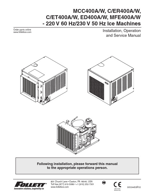
MCC400A/W, C/ER400A/W,C/ET400A/W, ED400A/W, MFE400A/W - 220 V 60 Hz/230 V 50 Hz Ice Machines00124453R12Installation, Operation and Service ManualOrder parts online 230V 50Hz models only2 400A/W 220 V 60 Hz/230 V/50 Hz Ice Machines400A/W 220 V 60 Hz/230 V/50 Hz Ice Machines 3Table of contents4588101516191920202021212222222222232430313131313234Welcome to Follett Corporation ................................................................Specifications . . . . . . . . . . . . . . . . . . . . . . . . . . . . . . . . . . . . . . . . . . . . . . . . . . . . . . . . . . . . . . . . . . . . . . . . . . . . . .Installation .................................................................................Top mount ice machines . . . . . . . . . . . . . . . . . . . . . . . . . . . . . . . . . . . . . . . . . . . . . . . . . . . . . . . . . . . . . . . . . .RIDE ® ice machines. . . . . . . . . . . . . . . . . . . . . . . . . . . . . . . . . . . . . . . . . . . . . . . . . . . . . . . . . . . . . . . . . . . . . .Ventilation . . . . . . . . . . . . . . . . . . . . . . . . . . . . . . . . . . . . . . . . . . . . . . . . . . . . . . . . . . . . . . . . . . . . . . . . . .Ice transport tube . . . . . . . . . . . . . . . . . . . . . . . . . . . . . . . . . . . . . . . . . . . . . . . . . . . . . . . . . . . . . . . . . . . .Start up . . . . . . . . . . . . . . . . . . . . . . . . . . . . . . . . . . . . . . . . . . . . . . . . . . . . . . . . . . . . . . . . . . . . . . . . . . . .Cleaning/descaling and sanitizing ..............................................................Weekly . . . . . . . . . . . . . . . . . . . . . . . . . . . . . . . . . . . . . . . . . . . . . . . . . . . . . . . . . . . . . . . . . . . . . . . . . . . . . . . .Monthl . . . . . . . . . . . . . . . . . . . . . . . . . . . . . . . . . . . . . . . . . . . . . . . . . . . . . . . . . . . . . . . . . . . . . . . . . . . . . . . .Semi-annually . . . . . . . . . . . . . . . . . . . . . . . . . . . . . . . . . . . . . . . . . . . . . . . . . . . . . . . . . . . . . . . . . . . . . . . . . . .Service Ice machine operation . . . . . . . . . . . . . . . . . . . . . . . . . . . . . . . . . . . . . . . . . . . . . . . . . . . . . . . . . . . . . . . . . . . .Technical specifications . . . . . . . . . . . . . . . . . . . . . . . . . . . . . . . . . . . . . . . . . . . . . . . . . . . . . . . . . . . . . . . . . . .Refrigeration system diagram . . . . . . . . . . . . . . . . . . . . . . . . . . . . . . . . . . . . . . . . . . . . . . . . . . . . . . . . . . .C/ET400A/W wiring diagram . . . . . . . . . . . . . . . . . . . . . . . . . . . . . . . . . . . . . . . . . . . . . . . . . . . . . . . . . . . .Refrigeration pressure data . . . . . . . . . . . . . . . . . . . . . . . . . . . . . . . . . . . . . . . . . . . . . . . . . . . . . . . . . . . . .Compressor data . . . . . . . . . . . . . . . . . . . . . . . . . . . . . . . . . . . . . . . . . . . . . . . . . . . . . . . . . . . . . . . . . . . . .Gearmotor data . . . . . . . . . . . . . . . . . . . . . . . . . . . . . . . . . . . . . . . . . . . . . . . . . . . . . . . . . . . . . . . . . . . . . . Electrical control system operation . . . . . . . . . . . . . . . . . . . . . . . . . . . . . . . . . . . . . . . . . . . . . . . . . . . . . . .Refrigeration system . . . . . . . . . . . . . . . . . . . . . . . . . . . . . . . . . . . . . . . . . . . . . . . . . . . . . . . . . . . . . . . . . . . . . .Service procedures . . . . . . . . . . . . . . . . . . . . . . . . . . . . . . . . . . . . . . . . . . . . . . . . . . . . . . . . . . . . . . . . . . . . . . .Evaporator disassembly . . . . . . . . . . . . . . . . . . . . . . . . . . . . . . . . . . . . . . . . . . . . . . . . . . . . . . . . . . . . . . .Evaporator reassembly . . . . . . . . . . . . . . . . . . . . . . . . . . . . . . . . . . . . . . . . . . . . . . . . . . . . . . . . . . . . . . . .Gearmotor replacement . . . . . . . . . . . . . . . . . . . . . . . . . . . . . . . . . . . . . . . . . . . . . . . . . . . . . . . . . . . . . . .Troubleshooting .............................................................................Replacement parts ..........................................................................Welcome to FollettFollett equipment enjoys a well-deserved reputation for excellent performance, long-term reliability and outstanding after-the-sale support. To ensure that this equipment delivers that same degree of service, we ask that you reviewthe installation portion of this manual before beginning to install the unit. Our instructions are designed to help you achieve a trouble-free installation. Should you have any questions or require technical help at any time, please call our technical service group at (877) 612-5086 or +1 (610) 252-7301.Note: T o expedite assistance, all correspondence or communication MUST include the model number, serial number and complete and detailed explanation of the problem.Before you beginAfter uncrating and removing all packing material, inspect the equipment for concealed shipping damage. If damage is found, notify the shipper immediately and contact Follett Corporation so that we can help in the filing of a claim, if necessary. Check your paperwork to determine which model you have. Follett model numbers are designed to provide information about the type and capacity of Follett equipment. Following is an explanation of the different model numbers in the400 series.4 400A/W 220 V 60 Hz/230 V/50 Hz Ice Machines400A/W 220 V 60 Hz/230 V/50 Hz Ice Machines 56 400A/W 220 V 60 Hz/230 V/50 Hz Ice MachinesDimensions and clearances230/50 modelsEntire front of ice machine must be clear of obstructions/connections to allow removal.305mm (12") clearance above ice machine for service.153mm (6") minimum clearance between exhaust side of ice machine and any adjacent equipment.MCC400A & C/ER400A – 457mm (18") minimum, 3m (10 ft) maximum clearance between discharge and air intake grilles.400A/W 220 V 60 Hz/230 V/50 Hz Ice Machines 7Dimensions and clearances220/60 modelsEntire front of ice machine must be clear of obstructions/connections to allow removal.305mm (12") clearance above ice machine for service.153mm (6") minimum clearance between exhaust side of ice machine and any adjacent equipment.MCC400A & C/ER400A – 457mm (18") minimum, 3m (10 ft) maximum clearance between discharge and air intake grilles.A – 3/4" MPT drainB – 3/8" OD push-in water inletC – 2" x 4" (51 mm x 102 mm) electrical boxD – 3/8" FPT condenser inletE – 3/8" FPT condenser drainF – Bin signal cord8 400A/W 220 V 60 Hz/230 V/50 Hz Ice Machines400A/W 220 V 60 Hz/230 V/50 Hz Ice Machines 9InstallationIce machine performance is very sensitive to the quality of installation. To ensure proper performance, ease of service and warranty coverage, it is critical that you follow the requirements detailed in this manual. If you cannot meet these requirements or have questions, call our technical service group immediately at (877) 612-5086 or +1 (610) 252-7301.Top mount ice machine installation procedureInstall ice machine and rough-in utilities1. Install ice storage bin in its final location.2. Install one supplied grommet in large knockout in base of ice machine and second supplied grommet in ice hole provided in top of ice storage bin.3. Rough in plumbing and electrical per specs provided.4. Flush all water lines before final hook up.5.Position ice machine with utility connections facing rear of bin.A. If new storage bin and ice machine – position ice machine with connections facing rear of bin.B. If using existing bin – place supplied gasket 64mm (2.5") from front of bin (Fig. 2). Position ice machinewith utility connections facing rear of bin.6. Make final plumbing and electrical connections.7. Working from inside bin storage area, push end of transport tube without fasteners up through grommets into ice machine, leaving about 51mm (2") hanging down in bin.8. Route free end of tube to evaporator port.9. Slip a hose clamp in free end of tube.10. Push free end of tube on evaporator port and tighten clamp, making sure clamp is positioned on evaporator side of flange.11.Position ice tube under float bracket retaining tab.Fig. 1Fig. 2 – Replacing existing ice machines12. Carefully slip ice level control stat alongside transport tube through both grommets and down into bin.13. Run ice level control stat down through one side of cap tube fasteners attached to ice transport tube, form a 180˚ bend at end of tube and run back up through fastener (Fig. 1).14. Adjust loop length to provide desired ice level. Loop must below end of ice transport tube.15.Carefully bend end of cap tube to prevent it from slipping out of clamp.Before turning power on1. Clean and sanitize ice storage bin in accordance with cleaning procedure in ice storage bin installationinformation packed with ice storage bin.2. Turn water to ice machine on.3. Remove cover on float reservoir.4. Push down on float to force water out overflow tube and into evaporator drain pan.5. Check that water drains freely from evaporator drain pan.6. Lift float and check that float valve shuts off incoming water when raised.After turning power on1. Turn power to ice machine on and confirm that gearmotor, compressor andfan motor start immediately.2. Check that ice begins to enter bin within approximately 10 minutes.3. With ice machine running, check that float reservoir water level is approximately 10mm (3/8") below internaloverflow and adjust to this level (raised line on side of reservoir) if necessary.4. After making ice for 10 minutes, put ice against ice level control stat cap tube and check that ice machineshuts down.5. Warm ice level control stat with your fingers and check that ice machine restarts in approximately 20 minutes.(Bin must be calling for ice.)10400A/W 220 V 60 Hz/230 V/50 Hz Ice MachinesNote: Diagram intended as guide only.Field wiring diagramsField wiring diagram is intended only to aid electrician or technician in understanding how equipment works.Should local codes require a hard-wired connection and/or shielded wiring, eliminate the cord and plug(s) and follow the appropriate field wiring diagram.MCC400A/W and C/ER400A/W ice machines have separate power supply from dispenser.Electric disconnects required within 3m (10 ft) for all hard-wired connections.Recommended junction box preparation of hard-wired RIDE model ice machines. 1. Replace upper (power) strain relief with a cord connector.2. Mount two 51mm x 102mm (2" x 4") junction boxes using supplied holes in ice machine face.3. Make power and bin signal connections.Step 2 – Installing ice machine on slide-out trackA. When ice machine is shipped with slide-out track accessory (follow either A or B)1. Connect inlet water, drain, and power supply to back of vertical utility panel.2. Place ice machine on slide-out track assembly.3. Connect drain and water lines.4. Connect electrical cords from ice machine to appropriate plug and connect to power supply.B. When ice machine is installed in and shipped with counter1. Remove two outer rear screws from ice machine and install supplied spacer and screw (Fig. 3).2. Place ice machine on slide-out track assembly.3. Connect drain and water lines.4. Connect electrical cords from ice machine to appropriate plug and connect to power supply.5. Remove pin from adjustable leg.6. Place hold-down strap over leg block and secure strap to slide-out assembly with supplied screws (Fig. 4).7. Reinstall pin in leg block.8. At job site remove hold-down strap and make utility connections at rear utility panel.RIDE model ice machine ventilation and exhaust requirementsFabricator-supplied, custom air intake grilles must have 305mm x 305mm (12" x 12") opening yielding 645 sq. cm (100 sq. inches) of open air space within duct perimeter. Block off any open area outside of the air duct.Intake air requirements — air-cooled ice machines (MCC400A & C/ER400A only)1. Check that 51mm (2") duct is installed on condenser front.2. Cut a 305mm x 305mm (12" x 12") opening in counter face to align with duct.3. Position ice machine to mate duct flush with back of counter opening.4. Install supplied grille on outside of counter opening.Exhaust air — all ice machines (MCC400A/W & C/ER400A/W)Provide 645 sq. cm. (100 sq. in) of counter opening for exhaust air at least 457mm (18") from intake opening but not more than 3m (10 ft) away.Front viewthrough louverProvide at least 645 sq. cm(100 sq. inches) of counter openingfor exhaust airRIDE model ice machine ice transport tube installationIncorrect ice transport tube installation can result in wet ice and dispensing problems. Follow guidelines below to ensure correct installation. Call factory for assistance if you are unable to meet these requirements.General requirementsMaximum length of tube run – 6m (20 ft). Factory approval required for longer runs.Run tube without dips.One continuous length of tube; no splices.Minimum radius of bends in tube – 153mm (6") inside radius.Maximum number of bends – 6.Insulation on entire run of ice tube.Procedure1. Select side, rear or top knockout in ice machine cabinet for tube entrance.2. Install supplied grommet in knockout.3. Remove ice machine top panel.4. Install supplied insulation on entire length of tube.5. Run insulated tube without dips between ice machine and dispenser and secure in place.6. Cut insulation off tube where tube enters grommet.7. Slide end of tube without insulation through grommet and run to evaporator port.8. Cut tube to that length.9. Install a section of insulation on tube from grommet to evaporator port.10. Slip supplied hose clamp over free end of tube.11. Pull insulation back from free end of tube.12. Push tube on evaporator port.13. Position clamp behind lip on evaporator port and tighten clamp.Additional ice transport tube connection specifications for Vision™ series ice and beverage dispensers1. Push one end of ice transport tube(s) through hole(s) provided in side of dispenser.2. Route tube into ice tube bracket inside dispenser and engage bracket tabs in holes located in end of ice transporttube(s) (see drawings below).3. Verify bin thermostat capillary tube is mounted correctly (see drawings below).Ice tube retainer bracketBin thermostat capillary tube mountingIce transport tube installation detail Heat end of transport tube in cup of 71 C (160 F) hot water to soften (1) and spread with pliers before making connection (2) .C/ET400A/W wiring diagramFollett ice machines used on top of an ice storage bin (C/ET400A/W) have a slightly different circuitry. A diagram for these ice machines is shown below. The operational and diagnostic stages for these ice machines will be otherwise the same as the following stages 1 - 10.Troubleshooting chartFlashing water LED at any time indicates that water signal to board had been lost for more than one second.T en-second delay: There is a 10 second delay in reaction to loss of water (WTR) or bin (B-E) signals. If signals are not lost for more than 10 seconds, no reaction will occur.Troubleshooting chartReplacement partsAir-cooled ice machinesOrder parts online Air-cooled ice machines Order parts onlineWater-cooled ice machines before serial number C57245Order parts online Water-cooled ice machines before serial number C57245Order parts onlineWater-cooled ice machines after serial number C57244Order parts onlineEvaporatorFlaker-specific componentsOrder parts online 400A/W 220 V 60 Hz/230 V/50 Hz Ice Machines 41Electrical componentsOrder parts online Order parts online Water treatment accessories for Symphony ice and water dispensers42400A/W 220 V 60 Hz/230 V/50 Hz Ice MachinesOrder parts online400A/W 220 V 60 Hz/230 V/50 Hz Ice Machines 4300124453R12© Follett Corporation 2/14801 Church Lane • Easton, P A 18040, USA T oll free (877) 612-5086 • +1 (610) 230V 50Hzmodels onlyMaestro, Harmony, SafeCLEAN, Symphony and Vision are trademarks of Follett Corporation.Chewblet, RIDE and Follett are registered trademarks, and Horizon is a trademark of Follett Corporation, registered in US.。
富士变频器参数

参数名称设定值备注参数推荐值F00 口令输入 ****F01 频率设定1 1F02 运行操作方式选择 1F03 最高输出频率1 50hzF04 基本频率1 50hzF05 额定电压1 380vF06 最高电压1 380vF07 加减速时间1 3.0*F08 加减速时间2 3.0*F09 转矩提升1 0F10 电子热继电器动作1 2F11 电子热继电器动作值电机额定电流的 100%F12 热时间常数 22KW以下为5.0;30KW以下为10.0F13 制动电子热继电器动作 0F14 瞬时停电的动作选择 1F15 频率限制上限 60hzF16 频率限制下限 0hzF17 频率设定增益 100%F18 偏置频率 0F20 直流制动开始频率 0.1F21 直流制动值 1%F22 直流制动时间 0.1SF23 启动频率 0F24 保持时间 0F25 停止频率 0.1F26 载波频率 10F27 电机运行声音 0F30 FMA端子 100F31 FMA端子 0* 根据具体要求选择F33 FMA端子(脉冲率) 1440F34 FMA端子(电压调整) 0F35 FMA端子(功能选择) 0F36 30RY模式 0F40 驱动转矩1 200F41 驱动转矩1 200F42 转矩向量 0扩展端子功能E:E01 X1端子功能 0(多段速度1)E02 X2端子功能 1(多段速度2)E03 X3端子功能 2(多段速度3)E04 X4端子功能 8(异常复位)E05 X5端子功能 4(未使用)E06 X6端子功能 4(未使用)E07 X7端子功能 4(未使用)E08 X8端子功能 4(未使用)E09 X9端子功能 9 (点动运行)E10 加速时间3 3.0* 根据实际情况设置E11 加速时间4 3.0* 根据实际情况设置E12 加速时间5 3.0* 根据实际情况设置E13 加速时间6 3.0* 根据实际情况设置E14 加速时间7 3.0* 根据实际情况设置E15 加速时间8 3.0* 根据实际情况设置E20 Y1端子功能 6(未使用)E21 Y2端子功能 38(速度一致)E22 Y3端子功能 39(制动控制)E23 Y4端子功能 6(未使用)E24 Y5端子功能 0(运行中)E25 Y5RY动作模式 0(ON信号激励)E30 速度一致检出幅 2.5hzE31 频率检测动作 60hzE32 滞环宽度 1hzE33 过负载预报 1(输出电流)E34 OL预报值电机的100%额定电流E35 OL预报时间 10SE36 检测频率2 60HZE37 过负载预报2 电机的100%额定电流E40 显示系数A 100E41 显示系数B -100E42 显示滤波器 0.5sE43 LED监视选择 0E44 停止时显示 0E45 LCD显示选择 0E46 显示语种 1(英语)E47 调整对比度 5频率控制参数C:C01 跳越频率1 0C02 跳越频率2 0C03 跳越频率3 0C04 跳越幅值3C05 多段速1 0C06 多段速2 0C07 多段速3 3C08 多段速4 9C09 多段速5 30C10 多段速6 45C11 多段速7 50C12 多段速0 0C13 蓄电池运行速度 0C20 点动频率 12C31 模拟输入(端子口) 0C32 偏移调整(端子口) 0C33 模拟输入滤波器 0.05电动机参数P:P01 电动机1的级数 6P02 电动机1的容量 18KWP03 电动机1的额定电流 30AP04 电动机1的自整定状态 1P05 电动机1的在线自整定 1(电动机停止);2(电动机旋转)P06 电动机1的空载电流 10AP07 电动机1的1次侧电阻×P08 电动机1的基本频率时的漏抗 *P09 电动机1的转差补偿量 * 整定后计算值高级功能H:H03 资料初始化 0H04 未用H05 未用H06 冷却风扇开关控制 0(不动作) "1" 表示动作(15KW 以上)H11 减速模式 "1" 为自由停车参数推荐值H12 瞬间过电流限制 0(不动作) 电梯专用设为"0"H14 电流限制时频率下降率 10%H18 转矩控制 0H26 PTC热敏电阻 0(不动作);1(动作) H27 热敏电阻动作值 1.6VH30 链接功能 0选件功能O:O01 速度指令方式选择“0”开环,“1”矢量闭环O02 速度指令滤波器时间常数 0.02SO03 编码器脉冲数 600(根据具体情况设定)O04 ASR P增益(高速) 18O05 ASR I增益 0.3O06 检测速度用滤波器时间常数 0.005O07 ASR P常数切换频率1 5O08 ASR P常数切换频率2 10O09 ASR P增益(低速) 40O10 多段速度指令定时器 0.005O11 加减速时间 6O12 加减速时间O13 S字设定1 50%O14 S字设定2 20%O15 S字设定3 20%O16 S字设定4 50%O17 S字设定5 50%O18 S字设定6 50%O19 S字设定7 50%O20 S字设定8 50%O21 S字设定9 50%O22 S字设定10 20%O24 转矩偏置启动定时器 0.2S O25 制动器释放时间 0.1S O27 速度一致 20% O29 控制开关 0 O30 数字量转矩偏置 0。
AT25F4096中文资料
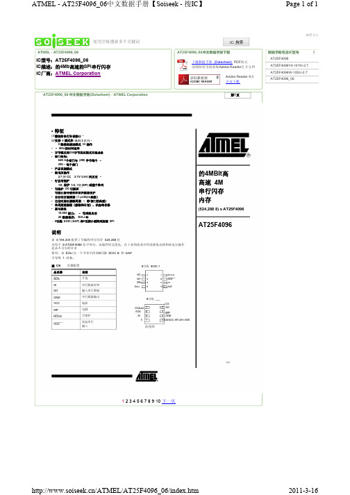
IC型号:AT25F4096_06 IC描述:的4Mb高速的SPI串行闪存 IC厂商:ATMEL Corporation
AT25F4096_06 中文数据手册(Datasheet) - ATMEL Corporation
第2 页
AT25F4096 启用该 (CS) 通过芯片选择引脚 (SI), ,并通过一个 3线接口的串行数据输入输出 (SO), (SCK). 串行数据和串行时钟 1/8, 组成的全部写周期是完全独立的计时 访问。 块写入顶级顶级 1/4, 1/2 WP 顶部或整个记忆体阵列的保护是启用的状态寄存器编程 。单独写使能和写禁止指令 提供额外的数据保护。硬件数据保护是通过提供 HOLD 针,以防止无意中写状态寄存器的尝试。该 +85°C 脚可暂停而不重置串行 序列任何串行通信。
/ATMEL/AT25F4096_06/3.htm
2011-3-16
ATMEL - AT25F4096_06中文数据手册(第4页)【Soiseek - 搜IC】
Page 1 of 1
IC型号大全
使用Firefox(火狐)浏览器提高10倍以上的搜索速度
ATMEL - AT25F4096_06 AT25F4096_06中文数据手册下载 下载数据手册 (Datasheet) PDF格式 请确保使用最新版Adobe Reader 打开文档 Adobe Reader 9.3 点击下载 数据手册包含IC型号 AT25F4096 AT25F4096Y4-10YH-2.7 AT25F4096W-10SU-2.7 AT25F4096_06
图 524,288 框图
8x2
AT25F4096
2454G–SFLSH–5/06
启用该 通过芯片选择引脚,并通过一个3 线接口的串行数据输入输出 串行数据和串行时钟