HD74ALVCH162374T中文资料
FCT2374A中文资料

PACKAGING INFORMATIONOrderableDevice Status (1)Package Type Package Drawing Pins Package Qty Eco Plan (2)Lead/Ball Finish MSL Peak Temp (3)74FCT2374ATSOCTE4ACTIVE SOIC DW 202000Green (RoHS &no Sb/Br)CU NIPDAU Level-1-260C-UNLIM 74FCT2374ATSOCTG4ACTIVE SOIC DW 202000Green (RoHS &no Sb/Br)CU NIPDAU Level-1-260C-UNLIM 74FCT2374CTSOCTE4ACTIVE SOIC DW 202000Green (RoHS &no Sb/Br)CU NIPDAU Level-1-260C-UNLIM 74FCT2374CTSOCTG4ACTIVE SOIC DW 202000Green (RoHS &no Sb/Br)CU NIPDAU Level-1-260C-UNLIM 74FCT2574ATQCTE4ACTIVE SSOP/QSOP DBQ 202500Green (RoHS &no Sb/Br)CU NIPDAU Level-2-260C-1YEAR 74FCT2574ATSOCTE4ACTIVE SOIC DW 202000Green (RoHS &no Sb/Br)CU NIPDAU Level-1-260C-UNLIM 74FCT2574ATSOCTG4ACTIVE SOIC DW 202000Green (RoHS &no Sb/Br)CU NIPDAU Level-1-260C-UNLIM 74FCT2574CTSOCTE4ACTIVE SOIC DW 202000Green (RoHS &no Sb/Br)CU NIPDAU Level-1-260C-UNLIM 74FCT2574CTSOCTG4ACTIVE SOIC DW 202000Green (RoHS &no Sb/Br)CU NIPDAU Level-1-260C-UNLIM CY74FCT2374ATQCT ACTIVE SSOP/QSOP DBQ 202500Green (RoHS &no Sb/Br)CU NIPDAU Level-2-260C-1YEAR CY74FCT2374ATQCTE4ACTIVE SSOP/QSOP DBQ 202500Green (RoHS &no Sb/Br)CU NIPDAU Level-2-260C-1YEAR CY74FCT2374ATQCTG4ACTIVE SSOP/QSOP DBQ 202500Green (RoHS &no Sb/Br)CU NIPDAU Level-2-260C-1YEAR CY74FCT2374ATSOC ACTIVE SOIC DW 2025Green (RoHS &no Sb/Br)CU NIPDAU Level-1-260C-UNLIM CY74FCT2374ATSOCE4ACTIVE SOIC DW 2025Green (RoHS &no Sb/Br)CU NIPDAU Level-1-260C-UNLIM CY74FCT2374ATSOCG4ACTIVE SOIC DW 2025Green (RoHS &no Sb/Br)CU NIPDAU Level-1-260C-UNLIM CY74FCT2374ATSOCT ACTIVE SOIC DW 202000Green (RoHS &no Sb/Br)CU NIPDAU Level-1-260C-UNLIM CY74FCT2374CTQCT ACTIVE SSOP/QSOP DBQ 202500Green (RoHS &no Sb/Br)CU NIPDAU Level-2-260C-1YEAR CY74FCT2374CTQCTE4ACTIVE SSOP/QSOP DBQ 202500Green (RoHS &no Sb/Br)CU NIPDAU Level-2-260C-1YEAR CY74FCT2374CTQCTG4ACTIVE SSOP/QSOP DBQ 202500Green (RoHS &no Sb/Br)CU NIPDAU Level-2-260C-1YEAR CY74FCT2374CTSOC ACTIVE SOIC DW 2025Green (RoHS &no Sb/Br)CU NIPDAU Level-1-260C-UNLIM CY74FCT2374CTSOCE4ACTIVE SOIC DW 2025Green (RoHS &no Sb/Br)CU NIPDAU Level-1-260C-UNLIM CY74FCT2374CTSOCG4ACTIVE SOIC DW 2025Green (RoHS &no Sb/Br)CU NIPDAU Level-1-260C-UNLIM CY74FCT2374CTSOCT ACTIVE SOIC DW 202000Green (RoHS &no Sb/Br)CU NIPDAU Level-1-260C-UNLIM CY74FCT2374TSOC ACTIVE SOIC DW 2025Green (RoHS &no Sb/Br)CU NIPDAU Level-1-260C-UNLIM CY74FCT2374TSOCE4ACTIVESOICDW2025Green (RoHS &no Sb/Br)CU NIPDAULevel-1-260C-UNLIM24-May-2007Orderable Device Status (1)Package Type Package Drawing Pins Package Qty Eco Plan (2)Lead/Ball Finish MSL Peak Temp (3)CY74FCT2374TSOCG4ACTIVE SOIC DW 2025Green (RoHS &no Sb/Br)CU NIPDAU Level-1-260C-UNLIM CY74FCT2374TSOCT ACTIVE SOIC DW 202000Green (RoHS &no Sb/Br)CU NIPDAU Level-1-260C-UNLIM CY74FCT2374TSOCTE4ACTIVE SOIC DW 202000Green (RoHS &no Sb/Br)CU NIPDAU Level-1-260C-UNLIM CY74FCT2374TSOCTG4ACTIVE SOIC DW 202000Green (RoHS &no Sb/Br)CU NIPDAU Level-1-260C-UNLIM CY74FCT2574ATQCT ACTIVE SSOP/QSOP DBQ 202500Green (RoHS &no Sb/Br)CU NIPDAU Level-2-260C-1YEAR CY74FCT2574ATQCTG4ACTIVE SSOP/QSOP DBQ 202500Green (RoHS &no Sb/Br)CU NIPDAU Level-2-260C-1YEAR CY74FCT2574ATSOC ACTIVE SOIC DW 2025Green (RoHS &no Sb/Br)CU NIPDAU Level-1-260C-UNLIM CY74FCT2574ATSOCE4ACTIVE SOIC DW 2025Green (RoHS &no Sb/Br)CU NIPDAU Level-1-260C-UNLIM CY74FCT2574ATSOCG4ACTIVE SOIC DW 2025Green (RoHS &no Sb/Br)CU NIPDAU Level-1-260C-UNLIM CY74FCT2574ATSOCT ACTIVE SOIC DW 202000Green (RoHS &no Sb/Br)CU NIPDAU Level-1-260C-UNLIM CY74FCT2574CTQCT ACTIVE SSOP/QSOP DBQ 202500Green (RoHS &no Sb/Br)CU NIPDAU Level-2-260C-1YEAR CY74FCT2574CTQCTE4ACTIVE SSOP/QSOP DBQ 202500Green (RoHS &no Sb/Br)CU NIPDAU Level-2-260C-1YEAR CY74FCT2574CTQCTG4ACTIVE SSOP/QSOP DBQ 202500Green (RoHS &no Sb/Br)CU NIPDAU Level-2-260C-1YEAR CY74FCT2574CTSOC ACTIVE SOIC DW 2025Green (RoHS &no Sb/Br)CU NIPDAU Level-1-260C-UNLIM CY74FCT2574CTSOCE4ACTIVE SOIC DW 2025Green (RoHS &no Sb/Br)CU NIPDAU Level-1-260C-UNLIM CY74FCT2574CTSOCG4ACTIVE SOIC DW 2025Green (RoHS &no Sb/Br)CU NIPDAU Level-1-260C-UNLIM CY74FCT2574CTSOCT ACTIVE SOIC DW 202000Green (RoHS &no Sb/Br)CU NIPDAU Level-1-260C-UNLIM CY74FCT2574TSOC ACTIVE SOIC DW 2025Green (RoHS &no Sb/Br)CU NIPDAU Level-1-260C-UNLIM CY74FCT2574TSOCE4ACTIVE SOIC DW 2025Green (RoHS &no Sb/Br)CU NIPDAU Level-1-260C-UNLIM CY74FCT2574TSOCG4ACTIVE SOIC DW 2025Green (RoHS &no Sb/Br)CU NIPDAU Level-1-260C-UNLIM CY74FCT2574TSOCT ACTIVE SOIC DW 202000Green (RoHS &no Sb/Br)CU NIPDAU Level-1-260C-UNLIM CY74FCT2574TSOCTE4ACTIVE SOIC DW 202000Green (RoHS &no Sb/Br)CU NIPDAU Level-1-260C-UNLIM CY74FCT2574TSOCTG4ACTIVESOICDW202000Green (RoHS &no Sb/Br)CU NIPDAULevel-1-260C-UNLIM(1)The marketing status values are defined as follows:ACTIVE:Product device recommended for new designs.LIFEBUY:TI has announced that the device will be discontinued,and a lifetime-buy period is in effect.NRND:Not recommended for new designs.Device is in production to support existing customers,but TI does not recommend using this part in a new design.PREVIEW:Device has been announced but is not in production.Samples may or may not be available.24-May-2007OBSOLETE:TI has discontinued the production of the device.(2)Eco Plan -The planned eco-friendly classification:Pb-Free (RoHS),Pb-Free (RoHS Exempt),or Green (RoHS &no Sb/Br)-please check /productcontent for the latest availability information and additional product content details.TBD:The Pb-Free/Green conversion plan has not been defined.Pb-Free (RoHS):TI's terms "Lead-Free"or "Pb-Free"mean semiconductor products that are compatible with the current RoHS requirements for all 6substances,including the requirement that lead not exceed 0.1%by weight in homogeneous materials.Where designed to be soldered at high temperatures,TI Pb-Free products are suitable for use in specified lead-free processes.Pb-Free (RoHS Exempt):This component has a RoHS exemption for either 1)lead-based flip-chip solder bumps used between the die and package,or 2)lead-based die adhesive used between the die and leadframe.The component is otherwise considered Pb-Free (RoHS compatible)as defined above.Green (RoHS &no Sb/Br):TI defines "Green"to mean Pb-Free (RoHS compatible),and free of Bromine (Br)and Antimony (Sb)based flame retardants (Br or Sb do not exceed 0.1%by weight in homogeneous material)(3)MSL,Peak Temp.--The Moisture Sensitivity Level rating according to the JEDEC industry standard classifications,and peak solder temperature.Important Information and Disclaimer:The information provided on this page represents TI's knowledge and belief as of the date that it is provided.TI bases its knowledge and belief on information provided by third parties,and makes no representation or warranty as to the accuracy of such information.Efforts are underway to better integrate information from third parties.TI has taken and continues to take reasonable steps to provide representative and accurate information but may not have conducted destructive testing or chemical analysis on incoming materials and chemicals.TI and TI suppliers consider certain information to be proprietary,and thus CAS numbers and other limited information may not be available for release.In no event shall TI's liability arising out of such information exceed the total purchase price of the TI part(s)at issue in this document sold by TI to Customer on an annualbasis.24-May-2007TAPE AND REELINFORMATIONPACKAGE MATERIALS INFORMATION19-May-2007DevicePackage Pins SiteReel Diameter (mm)Reel Width (mm)A0(mm)B0(mm)K0(mm)P1(mm)W (mm)Pin1Quadrant CY74FCT2374ATQCT DBQ 20MLA 33016 6.59.0 2.1816Q1CY74FCT2374ATSOCT DW 20MLA 3302410.813.0 2.71224Q1CY74FCT2374CTQCT DBQ 20MLA 33016 6.59.0 2.1816Q1CY74FCT2374CTSOCT DW 20MLA 3302410.813.0 2.71224Q1CY74FCT2374TSOCT DW 20MLA 3302410.813.0 2.71224Q1CY74FCT2574ATQCT DBQ 20MLA 33016 6.59.0 2.1816Q1CY74FCT2574ATSOCT DW 20MLA 3302410.813.0 2.71224Q1CY74FCT2574CTQCT DBQ 20MLA 33016 6.59.0 2.1816Q1CY74FCT2574CTSOCT DW 20MLA 3302410.813.0 2.71224Q1CY74FCT2574TSOCTDW20MLA3302410.813.02.71224Q1TAPE AND REEL BOX INFORMATIONDevicePackage Pins Site Length (mm)Width (mm)Height (mm)CY74FCT2374ATQCT DBQ 20MLA 0.00.00.0CY74FCT2374ATSOCT DW 20MLA 333.2333.231.75CY74FCT2374CTQCT DBQ 20MLA 0.00.00.0CY74FCT2374CTSOCT DW 20MLA 333.2333.231.75CY74FCT2374TSOCT DW 20MLA 333.2333.231.75CY74FCT2574ATQCT DBQ 20MLA 0.00.00.0CY74FCT2574ATSOCT DW 20MLA 333.2333.231.75CY74FCT2574CTQCT DBQ 20MLA 0.00.00.0CY74FCT2574CTSOCT DW 20MLA 333.2333.231.75CY74FCT2574TSOCTDW20MLA333.2333.231.7519-May-200719-May-2007IMPORTANT NOTICETexas Instruments Incorporated and its subsidiaries(TI)reserve the right to make corrections,modifications,enhancements, improvements,and other changes to its products and services at any time and to discontinue any product or service without notice. Customers should obtain the latest relevant information before placing orders and should verify that such information is current and complete.All products are sold subject to TI’s terms and conditions of sale supplied at the time of order acknowledgment.TI warrants performance of its hardware products to the specifications applicable at the time of sale in accordance with TI’s standard warranty.Testing and other quality control techniques are used to the extent TI deems necessary to support this warranty.Except where mandated by government requirements,testing of all parameters of each product is not necessarily performed.TI assumes no liability for applications assistance or customer product design.Customers are responsible for their products and applications using TI components.To minimize the risks associated with customer products and applications,customers should provide adequate design and operating safeguards.TI does not warrant or represent that any license,either express or implied,is granted under any TI patent right,copyright,mask work right,or other TI intellectual property right relating to any combination,machine,or process in which TI products or services are rmation published by TI regarding third-party products or services does not constitute a license from TI to use such products or services or a warranty or endorsement e of such information may require a license from a third party under the patents or other intellectual property of the third party,or a license from TI under the patents or other intellectual property of TI. Reproduction of information in TI data books or data sheets is permissible only if reproduction is without alteration and is accompanied by all associated warranties,conditions,limitations,and notices.Reproduction of this information with alteration is an unfair and deceptive business practice.TI is not responsible or liable for such altered documentation.Resale of TI products or services with statements different from or beyond the parameters stated by TI for that product or service voids all express and any implied warranties for the associated TI product or service and is an unfair and deceptive business practice.TI is not responsible or liable for any such statements.TI products are not authorized for use in safety-critical applications(such as life support)where a failure of the TI product would reasonably be expected to cause severe personal injury or death,unless officers of the parties have executed an agreement specifically governing such use.Buyers represent that they have all necessary expertise in the safety and regulatory ramifications of their applications,and acknowledge and agree that they are solely responsible for all legal,regulatory and safety-related requirements concerning their products and any use of TI products in such safety-critical applications,notwithstanding any applications-related information or support that may be provided by TI.Further,Buyers must fully indemnify TI and its representatives against any damages arising out of the use of TI products in such safety-critical applications.TI products are neither designed nor intended for use in military/aerospace applications or environments unless the TI products are specifically designated by TI as military-grade or"enhanced plastic."Only products designated by TI as military-grade meet military specifications.Buyers acknowledge and agree that any such use of TI products which TI has not designated as military-grade is solely at the Buyer's risk,and that they are solely responsible for compliance with all legal and regulatory requirements in connection with such use.TI products are neither designed nor intended for use in automotive applications or environments unless the specific TI products are designated by TI as compliant with ISO/TS16949requirements.Buyers acknowledge and agree that,if they use anynon-designated products in automotive applications,TI will not be responsible for any failure to meet such requirements. Following are URLs where you can obtain information on other Texas Instruments products and application solutions:Products ApplicationsAmplifiers Audio /audioData Converters Automotive /automotiveDSP Broadband /broadbandInterface Digital Control /digitalcontrolLogic Military /militaryPower Mgmt Optical Networking /opticalnetworkMicrocontrollers Security /securityRFID Telephony /telephonyLow Power /lpw Video&Imaging /videoWirelessWireless /wirelessMailing Address:Texas Instruments,Post Office Box655303,Dallas,Texas75265Copyright©2007,Texas Instruments Incorporated。
HD74LV1G04A中文资料

Output voltage range
Output : H or L VCC : OFF
Input clamp current Output clamp current Continuous output current Continuous current through VCC or GND Maximum power dissipation at Ta = 25°C (in still air) *3 Storage temperature Notes:
7
HD74LV1G04A
Test Circuit
VCC
Pulse generator
Input
Output
50 Ω
CL
Note: CL includes probe and jig capacitance.
• Waveforms
tr tf
90% Input 50% 10%
90% 50% 10%
VCC
Hysteresis voltage VH
1.8 2.5 3.3 5.0
Output voltage
VOH
Min to Max 1.65 2.3 3.0 4.5
VOL
Min to Max 1.65 2.3 3.0 4.5
Input current Quiescent supply current Output leakage current
I IK I OK IO I CC or IGND PT Tstg
–20 ±50 ±25 ±50 200 –65 to 150
mA mA mA mA mW °C
VI < 0 VO < 0 or VO > VCC VO = 0 to VCC
HD74ALVC16835TEL资料
To all our customersRegarding the change of names mentioned in the document, such as Hitachi Electric and Hitachi XX, to Renesas Technology Corp.The semiconductor operations of Mitsubishi Electric and Hitachi were transferred to Renesas Technology Corporation on April 1st 2003. These operations include microcomputer, logic, analog and discrete devices, and memory chips other than DRAMs (flash memory, SRAMs etc.) Accordingly, although Hitachi, Hitachi, Ltd., Hitachi Semiconductors, and other Hitachi brand names are mentioned in the document, these names have in fact all been changed to Renesas Technology Corp. Thank you for your understanding. Except for our corporate trademark, logo and corporate statement, no changes whatsoever have been made to the contents of the document, and these changes do not constitute any alteration to the contents of the document itself.Renesas Technology Home Page: Renesas Technology Corp.Customer Support Dept.April 1, 2003CautionsKeep safety first in your circuit designs!1. Renesas Technology Corporation puts the maximum effort into making semiconductor products betterand more reliable, but there is always the possibility that trouble may occur with them. Trouble with semiconductors may lead to personal injury, fire or property damage.Remember to give due consideration to safety when making your circuit designs, with appropriate measures such as (i) placement of substitutive, auxiliary circuits, (ii) use of nonflammable material or (iii) prevention against any malfunction or mishap.Notes regarding these materials1. These materials are intended as a reference to assist our customers in the selection of the RenesasTechnology Corporation product best suited to the customer's application; they do not convey any license under any intellectual property rights, or any other rights, belonging to Renesas Technology Corporation or a third party.2. Renesas Technology Corporation assumes no responsibility for any damage, or infringement of anythird-party's rights, originating in the use of any product data, diagrams, charts, programs, algorithms, or circuit application examples contained in these materials.3. All information contained in these materials, including product data, diagrams, charts, programs andalgorithms represents information on products at the time of publication of these materials, and are subject to change by Renesas Technology Corporation without notice due to product improvements or other reasons. It is therefore recommended that customers contact Renesas Technology Corporation or an authorized Renesas Technology Corporation product distributor for the latest product information before purchasing a product listed herein.The information described here may contain technical inaccuracies or typographical errors.Renesas Technology Corporation assumes no responsibility for any damage, liability, or other loss rising from these inaccuracies or errors.Please also pay attention to information published by Renesas Technology Corporation by various means, including the Renesas Technology Corporation Semiconductor home page().4. When using any or all of the information contained in these materials, including product data, diagrams,charts, programs, and algorithms, please be sure to evaluate all information as a total system before making a final decision on the applicability of the information and products. Renesas Technology Corporation assumes no responsibility for any damage, liability or other loss resulting from theinformation contained herein.5. Renesas Technology Corporation semiconductors are not designed or manufactured for use in a deviceor system that is used under circumstances in which human life is potentially at stake. Please contact Renesas Technology Corporation or an authorized Renesas Technology Corporation product distributor when considering the use of a product contained herein for any specific purposes, such as apparatus or systems for transportation, vehicular, medical, aerospace, nuclear, or undersea repeater use.6. The prior written approval of Renesas Technology Corporation is necessary to reprint or reproduce inwhole or in part these materials.7. If these products or technologies are subject to the Japanese export control restrictions, they must beexported under a license from the Japanese government and cannot be imported into a country other than the approved destination.Any diversion or reexport contrary to the export control laws and regulations of Japan and/or thecountry of destination is prohibited.8. Please contact Renesas Technology Corporation for further details on these materials or the productscontained therein.HD74ALVC1683518-bit Universal Bus Driver with 3-state OutputsADE-205-192E (Z)Preliminary6th. EditionJanuary 1999 DescriptionThe HD74ALVC16835 is an 18-bit universal bus driver designed for 2.3 V to 3.6 V Voperation.CCData flow from A to Y is controlled by output enable (OE). The device operates in the transparent mode when the latch enable (LE) input is high. The A data is latched if the clock (CLK) input is held at a high or low logic level. If LE is low, the A data is stored in the latch/flip flop on the low to high transition of the CLK. When OE is high, the outputs are in the high impedance state.To ensure the high impedance state during power up or power down, OE should be tied to Vthrough aCCpullup registor; the minimum value of the registor is determined by the current sinking capability of the driver.Features• Meets “PC SDRAM registered DIMM design support document, Rev. 1.2”• V CC = 2.3 V to 3.6 V• Typical V OL ground bounce < 0.8 V (@V CC = 3.3 V, Ta = 25°C)• Typical V OH undershoot > 2.0 V (@V CC = 3.3 V, Ta = 25°C)• High output current ±24 mA (@V CC = 3.0 V)HD74ALVC16835Function TableInputsOE LE CLK A Output YH X X X ZL H X L LL H X H HL L↑L LL L↑H H*1L L H X Y*2L L L X YH :High levelL :Low levelX :ImmaterialZ :High impedance↑ :Low to high transitionNotes: 1.Output level before the indicated steady-state input conditions were established, provided that CLK was high before LE went low.2.Output level before the indicated steady-state input conditions were established.HD74ALVC16835 Pin ArrangementHD74ALVC16835Absolute Maximum RatingsItem Symbol Ratings Unit Conditions Supply voltage range VCC–0.5 to 4.6VInput voltage range *1VI–0.5 to 4.6VOutput voltage range *1,2VO –0.5 to VCC+0.5VInput clamp current IIK –50mA VI< 0Output clamp current IOK ±50mA VO< 0 or VO> VCCContinuous output current IO ±50mA VO= 0 to VCCVCC , GND current / pin ICCor IGND±100mAMaximum power dissipation at Ta = 55°C (in still air) *3PT1W TSSOPStorage temperature range Tstg–65 to 150°CStresses beyond those listed under “absolute maximum ratings” may cause permanent damage to the device. These are stress ratings only, and functional operation of the device at these or any other conditions beyond those indicated under “recommended operating condition” is not implied. Exposure to absolute-maximum-rated conditions for extended periods may affect device reliability.Notes: 1.The input and output negative-voltage ratings may be exceeded if the input and output clamp current ratings are observed.2.The input and output positive-voltage ratings may be exceeded up to 4.6 V if the input and outputclamp-current ratings are observed.3.The maximum power dissipation is calculated using a junction temperature of 150°C and boardtrace length of 750 mils.Recommended Operating ConditionsItem Symbol Min Max Unit ConditionsSupply voltage VCC2.33.6VInput voltage VI 0VCCVOutput voltage VO 0VCCVHigh-level output current IOH —–12mA VCC= 2.3 V—–12VCC= 2.7 V—–24VCC= 3.0 VLow-level output current IOL —12mA VCC= 2.3 V—12VCC= 2.7 V—24VCC= 3.0 VInput transition rise or fall rate∆t/∆v010ns/V Operating free-air temperature Ta–4085°C Note: Unused or floating control pins must be held high or low.HD74ALVC16835 Logic DiagramHD74ALVC16835Electrical CharacteristicsTa = –40 to 85°CItem Symbol VCC(V)Min Max Unit Test ConditionsInput voltage VIH2.3 to 2.7 1.7—V2.7 to3.6 2.0—VIL2.3 to 2.7—0.7V2.7 to3.6—0.8Output voltage VOH 2.3 to 3.6VCC–0.2—V IOH= –100 µA2.3 2.0—IOH= –6 mA, VIH= 1.7 V2.3 1.7—IOH= –12 mA, VIH= 1.7 V2.7 2.2—IOH= –12 mA, VIH= 2.0 V3.0 2.4—IOH= –12 mA, VIH= 2.0 V3.0 2.0—IOH= –24 mA, VIH= 2.0 VVOL 2.3 to 3.6—0.2V IOL= 100 µA2.3—0.4IOL= 6 mA, VIL= 0.7 V2.3—0.7IOL= 12 mA, VIL= 0.7 V2.7—0.4IOL= 12 mA, VIL= 0.8 V3.0—0.55IOL= 24 mA, VIL= 0.8 VInput current IIN 3.6—±5.0µA VIN= VCCor GNDOff state output current IOZ 3.6—±10µA VOUT= VCCor GNDQuiescent supply current ICC 3.6—40µA VIN= VCCor GND∆ICC 3.0 to 3.6—750µA One input at (VCC–0.6)V,other inputs at VCCor GNDHD74ALVC16835 Switching Characteristics (Ta = –40 to 85°C)(V)Min Typ Max Unit From (Input)To (Output) Item Symbol VCC2.5±0.2150——MHzMaximum clock fmaxfrequency 2.7150——3.3±0.3150——2.5±0.2 1.0— 4.2ns A Y Propagation delay time tPLH2.7—— 4.2tPHL3.3±0.3 1.0— 3.62.5±0.2 1.3— 5.0LE Y2.7—— 4.93.3±0.3 1.3—4.22.5±0.2 1.4— 5.5CLK Y2.7—— 5.23.3±0.3 1.4—4.52.5±0.2 1.4— 5.5ns OE YOutput enable time tZH2.7—— 5.6tZL3.3±0.3 1.1—4.62.5±0.2 1.0— 4.5ns OE YOutput disable time tHZt2.7—— 4.3LZ3.3±0.3 1.3— 3.93.3 3.04.57.0pF Control inputsInput capacitance CIN3.3 3.0 6.09.0Data inputs3.3 3.07.09.0pF Y portsOutput capacitance COHD74ALVC16835Switching Characteristics (Ta = –40 to 85°C) (cont)Item Symbol VCC(V)Min Typ Max Unit From (Input)Setup time tsu2.5±0.2 2.2——ns Data before CLK↑2.7 2.1——3.3±0.3 1.7——2.5±0.2 1.9——Data before LE↓2.7 1.6——CLK “H”3.3±0.3 1.5——2.5±0.2 1.3——Data before LE↓2.7 1.1——CLK “L”3.3±0.3 1.0——Hold time th2.5±0.20.6——ns Data after CLK↑2.70.6——3.3±0.30.7——2.5±0.2 1.4——Data after LE↓2.7 1.7——CLK “H” or “L”3.3±0.3 1.4——Pulse width tw2.5±0.23.3——ns LE “H”2.73.3——3.3±0.3 3.3——2.5±0.23.3——CLK “H” or “L”2.73.3——3.3±0.3 3.3——Switching Characteristics (Ta = 0 to 85°C)Item Symbol VCC(V)Min Typ Max Unit FROM(Input)TO (Output)Propagation CL=0pF*1t PLH, t PHL 3.3±0.1650.9— 2.0ns A Ydelay time CL=50pF 3.3±0.165 1.0— 4.5CL=0pF*1 3.3±0.165 1.5— 3.0CLK YCL=50pF 3.3±0.165 1.7— 4.5CL=50pF t SSO*1, 2 3.3±0.165 1.7— 4.8CLK, A YOutput rise / fall time CL=50pF t TLH, t THL*13.3±0.165 1.0— 2.5volts/nsYNotes: 1.This parameter is characterized but not tested.2.tSSO: Simultaneous switching output time.Operating Characteristics (Ta = 25°C)Item Symbol VCC = 2.5±0.2 V VCC= 3.3±0.3 V Unit Test ConditionsTyp TypPower dissipation Outputs enable Cpd 22.024.5pF CL= 0, f = 10 MHzcapacitance Outputs disable 5.0 6.0 Test CircuitWaveforms – 2IV Characteristics for Register Output (Measured value)Package DimensionsUnit : mmCautions1.Hitachi neither warrants nor grants licenses of any rights of Hitachi’s or any third party’s patent,copyright, trademark, or other intellectual property rights for information contained in this document.Hitachi bears no responsibility for problems that may arise with third party’s rights, includingintellectual property rights, in connection with use of the information contained in this document.2.Products and product specifications may be subject to change without notice. Confirm that you have received the latest product standards or specifications before final design, purchase or use.3.Hitachi makes every attempt to ensure that its products are of high quality and reliability. However,contact Hitachi’s sales office before using the product in an application that demands especially high quality and reliability or where its failure or malfunction may directly threaten human life or cause risk of bodily injury, such as aerospace, aeronautics, nuclear power, combustion control, transportation,traffic, safety equipment or medical equipment for life support.4.Design your application so that the product is used within the ranges guaranteed by Hitachi particularly for maximum rating, operating supply voltage range, heat radiation characteristics, installationconditions and other characteristics. Hitachi bears no responsibility for failure or damage when used beyond the guaranteed ranges. Even within the guaranteed ranges, consider normally foreseeable failure rates or failure modes in semiconductor devices and employ systemic measures such as fail-safes, so that the equipment incorporating Hitachi product does not cause bodily injury, fire or other consequential damage due to operation of the Hitachi product.5.This product is not designed to be radiation resistant.6.No one is permitted to reproduce or duplicate, in any form, the whole or part of this document without written approval from Hitachi.7.Contact Hitachi’s sales office for any questions regarding this document or Hitachi semiconductor products.Semiconductor & IC Div.Nippon Bldg., 2-6-2, Ohte-machi, Chiyoda-ku, Tokyo 100-0004, Japan Tel: Tokyo (03) 3270-2111 Fax: (03) 3270-5109Copyright © Hitachi, Ltd., 1998. All rights reserved. Printed in Japan.Hitachi Asia Pte. Ltd.16 Collyer Quay #20-00Hitachi TowerSingapore 049318Tel: 535-2100Fax: 535-1533URLNorthAmerica : http:/Europe : /hel/ecg Asia (Singapore): .sg/grp3/sicd/index.htm Asia (Taiwan): /E/Product/SICD_Frame.htm Asia (HongKong): /eng/bo/grp3/index.htm Japan : http://www.hitachi.co.jp/Sicd/indx.htmHitachi Asia Ltd.Taipei Branch Office3F, Hung Kuo Building. No.167, Tun-Hwa North Road, Taipei (105)Tel: <886> (2) 2718-3666Fax: <886> (2) 2718-8180Hitachi Asia (Hong Kong) Ltd.Group III (Electronic Components)7/F., North Tower, World Finance Centre,Harbour City, Canton Road, Tsim Sha Tsui,Kowloon, Hong Kong Tel: <852> (2) 735 9218Fax: <852> (2) 730 0281 Telex: 40815 HITEC HXHitachi Europe Ltd.Electronic Components Group.Whitebrook ParkLower Cookham Road MaidenheadBerkshire SL6 8YA, United Kingdom Tel: <44> (1628) 585000Fax: <44> (1628) 778322Hitachi Europe GmbHElectronic components Group Dornacher Straße 3D-85622 Feldkirchen, Munich GermanyTel: <49> (89) 9 9180-0Fax: <49> (89) 9 29 30 00Hitachi Semiconductor (America) Inc.2000 Sierra Point Parkway Brisbane, CA 94005-1897Tel: <1> (800) 285-1601Fax: <1> (303) 297-0447For further information write to:。
74HC164D中文资料 参数及应用

74HC164D中文资料参数SN54HC164,/SN74HC164是8位移位寄存器,当其中一个(或二个)选通串行输入端的低电平禁止进入新数据,并把第一个触发器在下一个时钟脉冲来后复位到低电平时,门控串行输入端(A 和B)可完全控制输入数据。
一个高电平输入后就使另一个输入端赋能,这个输入就决定了第一个触发器的状态。
虽然不管时钟处于高电平或低电平时,串行输入端的数据都可以被改变,但只有满足建立条件的信息才能被输入。
时钟控制发生在时钟输入由低电平到高电平的跃变上。
为了减小传输线效应,所有输入端均采用二极管钳位。
功能表:Inputs输入Outputs输出CLRCLK A B QA QB ...QHL X X X L L LH L X X QAQBQH0H↑H H H QAnQGnH↑L X L QAnQGnH↑X L L QAnQGnH=高电平(稳定态)L=低电平(稳定态)×=不定↑=从低电平转换到高电平QA0…QH0=在稳定态输入条件建立前QA…QH 的相应电平QAn…QHn=在最近的时钟输入条件(↑)建立前QA…QH 的相应电平,表示移位一位图1 逻辑图(正逻辑)图2 引脚图Absolute Maximum Ratings绝对最大额定值Supply voltage range, 电源电压范围VCC–0.5 V to 7V Input clamp current, 输入钳位电流IIK (VI < 0 or VI > VCC) (seeNote 1)±20 mA Output clamp current,输出钳位电流IOK (VO < 0 or VO > VCC) (seeNote 1)±20 mA Continuous output current,连续输出电流IO (VO = 0 to VCC)±25 mA Continuous current through 连续通过电流VCC or GND±50 mA封装热阻thermal impedance, θJA (see Note 2):D 封装86℃/W N 封装80℃/W NS 封装76℃/W PW 封装113℃/WStorage temperature range, Tstg储存温度范围–65℃ to 150℃DC SPECIFICATIONS直流电气规格表:符号Parameter 参数SN54HC164SN74HC164最小典型最大最小典型最大VCCSupply Voltage 电源电压256256图3 参数测量信息图4 typical clear, shift, and clear sequence典型清除、移位和清除时序应用电路:图5 LCD驱动电路图6 LED驱动电路74HC164中文资料参数时间:2016-06-15 来源:资料室作者:编号:颖展电子SN54HC164,/SN74HC164是8位移位寄存器,当其中一个(或二个)选通串行输入端的低电平禁止进入新数据,并把第一个触发器在下一个时钟脉冲来后复位到低电平时,门控串行输入端(A 和B)可完全控制输入数据。
HD74ALVCH16827T资料
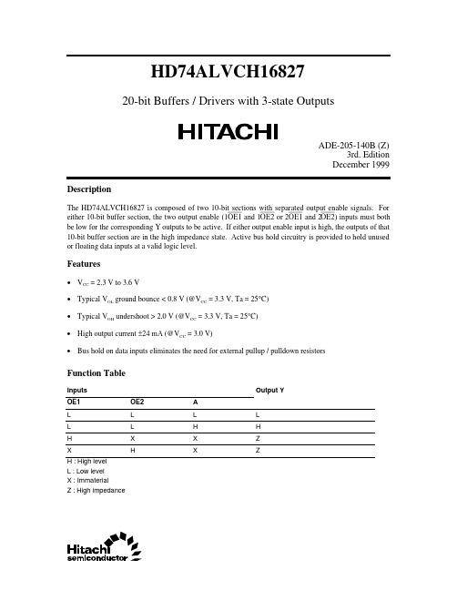
HD74ALVCH1682720-bit Buffers / Drivers with 3-state OutputsADE-205-140B (Z)3rd. EditionDecember 1999 DescriptionThe HD74ALVCH16827 is composed of two 10-bit sections with separated output enable signals. For either 10-bit buffer section, the two output enable (1OE1 and 1OE2 or 2OE1 and 2OE2) inputs must both be low for the corresponding Y outputs to be active. If either output enable input is high, the outputs of that 10-bit buffer section are in the high impedance state. Active bus hold circuitry is provided to hold unused or floating data inputs at a valid logic level.Features• V CC = 2.3 V to 3.6 V• Typical V OL ground bounce < 0.8 V (@V CC = 3.3 V, Ta = 25°C)• Typical V OH undershoot > 2.0 V (@V CC = 3.3 V, Ta = 25°C)• High output current ±24 mA (@V CC = 3.0 V)• Bus hold on data inputs eliminates the need for external pullup / pulldown resistorsFunction TableInputs Output YOE1OE2AL L L LL L H HH X X ZX H X ZH : High levelL : Low levelX : ImmaterialZ : High impedanceHD74ALVCH16827 Pin Arrangement2HD74ALVCH168273Absolute Maximum RatingsItemSymbol Ratings Unit ConditionsSupply voltage V CC –0.5 to 4.6V Input voltage *1V I –0.5 to 4.6V Output voltage *1, 2V O –0.5 to V CC +0.5V Input clamp current I IK –50mA V I < 0Output clamp current I OK ±50mA V O < 0 or V O > V CC Continuous output current I O±50mA V O = 0 to V CC V CC , GND current / pin I CC or I GND ±100mA Maximum power dissipation at Ta = 55°C (in still air) *3P T 1W TSSOP Storage temperature Tstg–65 to 150°CNotes:Stresses beyond those listed under “absolute maximum ratings” may cause permanent damage to the device. These are stress ratings only, and functional operation of the device at these or any other conditions beyond those indicated under “recommended operating conditions” is not implied. Exposure to absolute maximum rated conditions for extended periods may affect device reliability.1.The input and output negative voltage ratings may be exceeded if the input and output clampcurrent ratings are observed.2.This value is limited to 4.6 V maximum.3.The maximum package power dissipation is calculated using a junction temperature of 150°Cand a board trace length of 750 mils.Recommended Operating ConditionsItemSymbol Min Max Unit ConditionsSupply voltage V CC 2.3 3.6V Input voltage V I 0V CC V Output voltageV O 0V CC V High level output currentI OH—–12mAV CC = 2.3 V —–12V CC = 2.7 V —–24V CC = 3.0 V Low level output currentI OL—12mA V CC = 2.3 V —12V CC = 2.7 V —24V CC = 3.0 V Input transition rise or fall rate ∆t / ∆v 010ns / V Operating temperatureTa–4085°C Note:Unused control inputs must be held high or low to prevent them from floating.HD74ALVCH16827 Logic Diagram4HD74ALVCH168275Electrical Characteristics (Ta = –40 to 85°C)Item Symbol V CC (V) *1Min Max Unit Test ConditionsInput voltageV IH 2.3 to 2.7 1.7—V2.7 to3.6 2.0—V IL2.3 to 2.7—0.72.7 to3.6—0.8Output voltageV OHMin to Max V CC –0.2—VI OH = –100 µA2.3 2.0—I OH = –6 mA, V IH = 1.7 V 2.3 1.7—I OH = –12 mA, V IH = 1.7 V 2.7 2.2—I OH = –12 mA, V IH = 2.0 V3.0 2.4—I OH = –12 mA, V IH = 2.0 V 3.02.0—I OH = –24 mA, V IH = 2.0 V V OLMin to Max —0.2I OL = 100 µA2.3—0.4I OL = 6 mA, V IL = 0.7 V 2.3—0.7I OL = 12 mA, V IL = 0.7 V 2.7—0.4I OL = 12 mA, V IL = 0.8 V3.0—0.55I OL = 24 mA, V IL = 0.8 V Input currentI IN 3.6—±5µA V IN = V CC or GND I IN (hold)2.345—V IN = 0.7 V 2.3–45—V IN = 1.7 V3.075—V IN = 0.8 V 3.0–75—V IN = 2.0 V 3.6—±500V IN = 0 to 3.6 V Off state output current *2I OZ 3.6—±10µA V OUT = V CC or GND Quiescent supply current I CC3.6—40µA V IN = V CC or GND∆I CC3.0 to 3.6—750µA V IN = one input at (V CC –0.6) V,other inputs at V CC or GND Notes: 1.For conditions shown as Min or Max, use the appropriate values under recommended operatingconditions.2.For I/O ports, the parameter I OZ includes the input leakage current.HD74ALVCH168276Switching Characteristics (Ta = –40 to 85°C)ItemSymbol V CC (V)Min Typ Max Unit FROM (Input)TO(Output)Propagation delay timet PLH 2.5±0.2 1.0— 4.1nsAYt PHL2.7——3.93.3±0.3 1.0— 3.4Output enable timet ZH 2.5±0.2 1.0— 6.0nsOEYt ZL2.7—— 5.73.3±0.3 1.0—4.7Output disable timet HZ 2.5±0.2 1.9— 5.6nsOEYt LZ2.7—— 4.93.3±0.3 1.3—4.5Input capacitance C IN 3.3— 3.5—pFControl inputs 3.3— 6.0–Data inputs Output capacitanceC O3.3—7.5—pF OutputsHD74ALVCH168277HD74ALVCH16827Package DimensionsUnit : mm8HD74ALVCH168279Cautions1.Hitachi neither warrants nor grants licenses of any rights of Hitachi’s or any third party’s patent,copyright, trademark, or other intellectual property rights for information contained in this document.Hitachi bears no responsibility for problems that may arise with third party’s rights, including intellectual property rights, in connection with use of the information contained in this document.2.Products and product specifications may be subject to change without notice. Confirm that you have received the latest product standards or specifications before final design, purchase or use.3.Hitachi makes every attempt to ensure that its products are of high quality and reliability. However,contact Hitachi’s sales office before using the product in an application that demands especially high quality and reliability or where its failure or malfunction may directly threaten human life or cause risk of bodily injury, such as aerospace, aeronautics, nuclear power, combustion control, transportation,traffic, safety equipment or medical equipment for life support.4.Design your application so that the product is used within the ranges guaranteed by Hitachi particularly for maximum rating, operating supply voltage range, heat radiation characteristics, installationconditions and other characteristics. Hitachi bears no responsibility for failure or damage when used beyond the guaranteed ranges. Even within the guaranteed ranges, consider normally foreseeable failure rates or failure modes in semiconductor devices and employ systemic measures such as fail-safes, so that the equipment incorporating Hitachi product does not cause bodily injury, fire or other consequential damage due to operation of the Hitachi product.5.This product is not designed to be radiation resistant.6.No one is permitted to reproduce or duplicate, in any form, the whole or part of this document without written approval from Hitachi.7.Contact Hitachi’s sales office for any questions regarding this document or Hitachi semiconductor products.Hitachi, Ltd.Semiconductor & Integrated Circuits.Nippon Bldg., 2-6-2, Ohte-machi, Chiyoda-ku, Tokyo 100-0004, Japan Tel: Tokyo (03) 3270-2111 Fax: (03) 3270-5109Copyright ' Hitachi, Ltd., 1999. All rights reserved. Printed in Japan.Hitachi Asia Pte. Ltd.16 Collyer Quay #20-00Hitachi TowerSingapore 049318Tel: 535-2100Fax: 535-1533URLNorthAmerica : http:/Europe : /hel/ecg Asia (Singapore): .sg/grp3/sicd/index.htm Asia (Taiwan): /E/Product/SICD_Frame.htm Asia (HongKong): /eng/bo/grp3/index.htm Japan : http://www.hitachi.co.jp/Sicd/index.htmHitachi Asia Ltd.Taipei Branch Office3F, Hung Kuo Building. No.167, Tun-Hwa North Road, Taipei (105)Tel: <886> (2) 2718-3666Fax: <886> (2) 2718-8180Hitachi Asia (Hong Kong) Ltd.Group III (Electronic Components)7/F., North Tower, World Finance Centre,Harbour City, Canton Road, Tsim Sha Tsui,Kowloon, Hong Kong Tel: <852> (2) 735 9218Fax: <852> (2) 730 0281 Telex: 40815 HITEC HXHitachi Europe Ltd.Electronic Components Group.Whitebrook ParkLower Cookham Road MaidenheadBerkshire SL6 8YA, United Kingdom Tel: <44> (1628) 585000Fax: <44> (1628) 778322Hitachi Europe GmbHElectronic components Group Dornacher Stra§e 3D-85622 Feldkirchen, Munich GermanyTel: <49> (89) 9 9180-0Fax: <49> (89) 9 29 30 00Hitachi Semiconductor (America) Inc.179 East Tasman Drive,San Jose,CA 95134 Tel: <1> (408) 433-1990Fax: <1>(408) 433-0223For further information write to:。
74LVTH322373资料
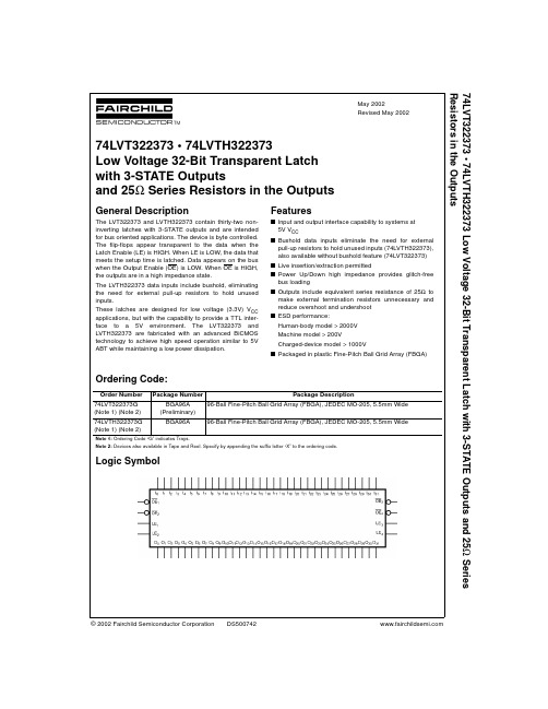
© 2002 Fairchild Semiconductor Corporation DS500742May 2002Revised May 200274LVT322373 • 74LVTH322373 Low Voltage 32-Bit Transparent Latch with 3-STATE Outputs and 25Ω Series Resistors in the Outputs74LVT322373 • 74LVTH322373Low Voltage 32-Bit Transparent Latch with 3-STATE Outputsand 25Ω Series Resistors in the OutputsGeneral DescriptionThe LVT322373 and LVTH322373 contain thirty-two non-inverting latches with 3-STATE outputs and are intended for bus oriented applications. The device is byte controlled.The flip-flops appear transparent to the data when the Latch Enable (LE) is HIGH. When LE is LOW, the data that meets the setup time is latched. Data appears on the bus when the Output Enable (OE) is LOW. When OE is HIGH,the outputs are in a high impedance state.The LVTH322373 data inputs include bushold, eliminating the need for external pull-up resistors to hold unused inputs.These latches are designed for low voltage (3.3V) V CC applications, but with the capability to provide a TTL inter-face to a 5V environment. The LVT322373 and LVTH322373 are fabricated with an advanced BiCMOS technology to achieve high speed operation similar to 5V ABT while maintaining a low power dissipation.Featuress Input and output interface capability to systems at 5V V CC s Bushold data inputs eliminate the need for external pull-up resistors to hold unused inputs (74LVTH322373),also available without bushold feature (74LVT322373)s Live insertion/extraction permitteds Power Up/Down high impedance provides glitch-free bus loading s Outputs include equivalent series resistance of 25Ω to make external termination resistors unnecessary and reduce overshoot and undershoot s ESD performance:Human-body model > 2000V Machine model > 200V Charged-device model > 1000Vs Packaged in plastic Fine-Pitch Ball Grid Array (FBGA)Ordering Code:Note 1: Ordering Code “G” indicates Trays.Note 2: Devices also available in Tape and Reel. Specify by appending the suffix letter “X” to the ordering code.Logic SymbolOrder Number Package Number Package Description74LVT322373G (Note 1) (Note 2)BGA96A (Preliminary)96-Ball Fine-Pitch Ball Grid Array (FBGA), JEDEC MO-205, 5.5mm Wide 74LVTH322373G (Note 1) (Note 2)BGA96A96-Ball Fine-Pitch Ball Grid Array (FBGA), JEDEC MO-205, 5.5mm Wide274L V T 322373 • 74L V T H 322373Connection Diagram (Top Thru View)Pin DescriptionsFBGA Pin AssignmentsTruth TableH = HIGH Voltage LevelL = LOW Voltage LevelX = ImmaterialZ = HIGH ImpedanceO o = Previous O o prior to HIGH-to-LOW transition of LEFunctional DescriptionThe LVT322373 and LVTH322373 contain thirty-two D-type latches with 3-STATE standard outputs. The device is byte con-trolled with each byte functioning identically, but independent of the other. Control pins can be shorted together to obtain full 32-bit operation. The following description applies to each byte. When the Latch Enable (LE n ) input is HIGH, data on the D n enters the latches. In this condition the latches are transparent, i.e, a latch output will change states each time its D input changes. When LE n is LOW, the latches store information that was present on the D inputs a setup time preceding the HIGH-to-LOW transition of LE n . The 3-STATE standard outputs are controlled by the Output Enable (OE n ) input. When OE n is LOW, the standard outputs are in the 2-state mode. When OE n is HIGH, the standard outputs are in the high impedance mode but this does not interfere with entering new data into the latches. Pin Names DescriptionOE n Output Enable Input (Active LOW)LE n Latch Enable Input I 0–I 31 InputsO 0–O 313-STATE Outputs123456A O 1O 0OE 1LE 1I 0I 1B O 3O 2GND GND I 2I 3C O 5O 4V CC1V CC1I 4I 5D O 7O 6GND GND I 6I 7E O 9O 8GND GND I 8I 9F O 11O 10V CC1V CC1I 10I 11GO 13O 12GND GND I 12I 13H O 14O 15OE 2LE 2I 15I 14J O 17O 16OE 3LE 3I 16I 17K O 19O 18GND GND I 18I 19L O 21O 20V CC2V CC2I 20I 21M O 23O 22GND GND I 22I 23N O 25O 24GND GND I 24I 25P O 27O 26V CC2V CC2I 26I 27R O 29O 28GND GND I 28I 29TO 30O 31OE 4LE 4I 31I 30InputsOutputsInputsOutputsLE 1OE 1I 0–I 7O 0–O 7LE 2OE 2I 8–I 15O 8–O 15X H X Z X H X Z H L L L H L L L H L H H H L H H L L X O 0L L X O 0Inputs Outputs Inputs Outputs LE 3OE 3I 16–I 23O 16–O 23LE 4OE 4I 24–I 31O 24–O 31X H X Z X H X Z H L L L H L L L H L H H H L H H LLXO 0LLXO 074LVT322373 • 74LVTH322373Logic DiagramsByte 1 (0:7)Byte 2 (8:15)Byte 3 (16:23)Byte 4 (24:31)V CC1 is associated with Bytes 1 and 2.V CC2 is associated with Bytes 3 and 4.Note: Please note that these diagrams are provided only for the understanding of logic operations and should not be used to estimate propagation delays. 474L V T 322373 • 74L V T H 322373Absolute Maximum Ratings (Note 3)Recommended Operating ConditionsNote 3: Absolute Maximum continuous ratings are those values beyond which damage to the device may occur. Exposure to these conditions or conditions beyond those indicated may adversely affect device reliability. Functional operation under absolute maximum rated conditions is not implied.Note 4: I O Absolute Maximum Rating must be observed.DC Electrical CharacteristicsSymbol ParameterValueConditionsUnits V CC Supply Voltage −0.5 to +4.6V V I DC Input Voltage −0.5 to +7.0VV O DC Output Voltage −0.5 to +7.0Output in 3-STATEV −0.5 to +7.0Output in HIGH or LOW State (Note 4)I IK DC Input Diode Current −50V I < GND mA I OK DC Output Diode Current −50V O < GND mA I O DC Output Current64V O > V CC Output at HIGH State mA 128V O > V CCOutput at LOW StateI CC DC Supply Current per Supply Pin ±64mA I GND DC Ground Current per Ground Pin ±128mAT STGStorage Temperature−65 to +150°CSymbol ParameterMin Max Units V CC Supply Voltage 2.7 3.6V V I Input Voltage5.5V I OH HIGH Level Output Current −12mA I OL LOW Level Output Current 12mAT AFree-Air Operating Temperature−4085°C ∆t/∆VInput Edge Rate, V IN = 0.8V to 2.0V, V CC = 3.0V10ns/VSymbol ParameterV CC T A = −40°C to +85°C Units Conditions(V)MinMax V IK Input Clamp Diode Voltage 2.7−1.2V I I = −18 mA V IH Input HIGH Voltage 2.7 - 3.6 2.0V V O ≤ 0.1V or V IL Input LOW Voltage 2.7 - 3.60.8V V O ≥ V CC − 0.1V V OH Output HIGH Voltage 2.7 - 3.6V CC − 0.2V I OH = −100 µA 3.0 2.0I OH = −12 mA V OL Output LOW Voltage 2.70.2V I OL = 100 µA 3.00.8I OL = 12 mA I I(HOLD)Bushold Input Minimum Drive 3.075µA V I = 0.8V −75V I = 2.0V I I(OD)Bushold Input Over-Drive 3.0500µA(Note 5)Current to Change State −500(Note 6)I IInput Current3.610µAV I = 5.5V Control Pins 3.6±1V I = 0V or V CC Data Pins3.6−5V I = 0V 1V I = V CCI OFF Power Off Leakage Current 0±100µA 0V ≤ V I or V O ≤ 5.5V I PU/PD Power up/down 3-STATE 0 - 1.5V ±100µA V O = 0.5V to 3.0V Output CurrentV I = GND or V CC I OZL 3-STATE Output Leakage Current 3.6−5µA V O = 0.5V I OZH 3-STATE Output Leakage Current 3.65µA V O = 3.0V I OZH +3-STATE Output Leakage Current 3.610µA V CC < V O ≤ 5.5V I CCH Power Supply Current (V CC1 or V CC2) 3.60.19mA Outputs HIGH I CCL Power Supply Current (V CC1 or V CC2) 3.65mA Outputs LOW I CCZPower Supply Current(V CC1 or V CC2)3.60.19mA Outputs Disabled74LVT322373 • 74LVTH322373DC Electrical Characteristics (Continued)Note 5: An external driver must source at least the specified current to switch from LOW-to-HIGH.Note 6: An external driver must sink at least the specified current to switch from HIGH-to-LOW.Note 7: This is the increase in supply current for each input that is at the specified voltage level rather than V CC or GND.Dynamic Switching Characteristics (Note 8)Note 8: Characterized in SSOP package. Guaranteed parameter, but not tested.Note 9: Max number of outputs defined as (n). n −1 data inputs are driven 0V to 3V. Output under test held LOW.AC Electrical CharacteristicsNote 10: Skew is defined as the absolute value of the difference between the actual propagation delay for any two separate outputs of the same device. The specification applies to any outputs switching in the same direction, either HIGH-to-LOW (t OSHL ) or LOW-to-HIGH (t OSLH ).Capacitance (Note 11)Note 11: Capacitance is measured at frequency f = 1 MHz, per MIL-STD-883, Method 3012.Symbol ParameterV CC T A = −40°C to +85°C Units Conditions(V)MinMax I CCZ +Power Supply Current(V CC1 or V CC2) 3.60.19mA V CC ≤ V O ≤ 5.5V,Outputs Disabled ∆I CCIncrease in Power Supply Current (V CC1 or V CC2)3.60.2mAOne Input at V CC − 0.6V (Note 7)Other Inputs at V CC or GNDSymbol ParameterV CC T A = 25°C Units Conditions (V)MinTyp MaxC L = 50 pF, R L = 500ΩV OLP Quiet Output Maximum Dynamic V OL 3.30.8V (Note 9)V OLVQuiet Output Minimum Dynamic V OL3.3−0.8V(Note 9)Symbol ParameterT A = −40°C to +85°C, C L = 50pF, R L = 500ΩUnitsV CC = 3.3V ± 0.3V V CC = 2.7VMin Max Min Max t PHL Propagation Delay 1.3 4.8 1.3 5.3ns t PLH D n to O n1.4 4.8 1.4 5.1t PHL Propagation Delay 1.7 5.0 1.7 5.1ns t PLH LE to O n1.4 5.1 1.4 5.8t PZL Output Enable Time1.6 5.0 1.6 6.0ns t PZH 1.0 5.4 1.0 6.6t PLZ Output Disable Time1.6 5.1 1.6 5.0ns t PHZ 1.8 5.41.8 5.7t S Setup Time, D n to LE 1.00.8ns t H Hold Time, D n to LE 1.0 1.1ns t W LE Pulse Width3.03.0ns t OSHL Output to Output Skew (Note 10) 1.0 1.0ns t OSLH1.0 1.0Symbol ParameterConditionsTypical Units C IN Input Capacitance V CC = Open, V I = 0V or V CC 4pF C OUTOutput CapacitanceV CC = 3.0V, V O = 0V or V CC8pF674L V T 322373 • 74L V T H 322373 L o w V o l t a g e 32-B i t T r a n s p a r e n t L a t c h w i t h 3-S T A T E O u t p u t s a n d 25Ω S e r i e s R e s i s t o r s i n t h e O u t p u t sPhysical Dimensions inches (millimeters) unless otherwise noted96-Ball Fine-Pitch Ball Grid Array (FBGA), JEDEC MO-205, 5.5mm WidePackage Number BGA96APreliminaryFairchild does not assume any responsibility for use of any circuitry described, no circuit patent licenses are implied and Fairchild reserves the right at any time without notice to change said circuitry and specifications.LIFE SUPPORT POLICYFAIRCHILD ’S PRODUCTS ARE NOT AUTHORIZED FOR USE AS CRITICAL COMPONENTS IN LIFE SUPPORT DEVICES OR SYSTEMS WITHOUT THE EXPRESS WRITTEN APPROVAL OF THE PRESIDENT OF FAIRCHILD SEMICONDUCTOR CORPORATION. As used herein:1.Life support devices or systems are devices or systems which, (a) are intended for surgical implant into the body, or (b) support or sustain life, and (c) whose failure to perform when properly used in accordance with instructions for use provided in the labeling, can be rea-sonably expected to result in a significant injury to the user. 2. A critical component in any component of a life support device or system whose failure to perform can be rea-sonably expected to cause the failure of the life support device or system, or to affect its safety or effectiveness.。
HD74ALVCH162244中文资料

1OE 1 1Y1 2 1Y2 3 GND 4 1Y3 5 1Y4 6 VCC 7 2Y1 8 2Y2 9 GND 10 2Y3 11 2Y4 12 3Y1 13 3Y2 14 GND 15 3Y3 16 3Y4 17 VCC 18 4Y1 19 4Y2 20 GND 21 4Y3 22 4Y4 23 4OE 24
—
0.4
IOL = 4 mA, VIL = 0.7 V
2.3
—
0.55
IOL = 6 mA, VIL = 0.7 V
3.0
—
0.55
IOL = 6 mA, VIL = 0.8 V
2.7
—
0.6
IOL = 8 mA, VIL = 0.8 V
3.0
—
0.8
IOL = 12 mA, VIL = 0.8 V
Features
• VCC = 2.3 V to 3.6 V • Typical VOL ground bounce < 0.8 V (@VCC = 3.3 V, Ta = 25°C) • Typical VOH undershoot > 2.0 V (@VCC = 3.3 V, Ta = 25°C) • High output current ±12 mA (@VCC = 3.0 V) • Bus hold on data inputs eliminates the need for external pullup / pulldown resistors • All outputs have equivalent 26 Ω series resistors, so no external resistors are required.
Item
HD74ALVC162834T资料

HD74ALVC16283418-bit Universal Bus Driver with 3-state Outputsand Inverted Latch EnableADE-205-217D (Z)5th. EditionDecember 1999 DescriptionThe HD74ALVC162834 is an 18-bit universal bus driver designed for 2.3 V to 3.6 V Voperation.CCData flow from A to Y is controlled by the output enable (OE). The device operates in the transparent mode when the latch enable (LE) is low. When LE is low, the A data is latched if the clock (CLK) input is held at a high or low logic level. If the LE is high, the A data is stored in the latch/flip flop on the low to high transition of CLK. When OE is high, the outputs are in the high impedance state.To ensure the high impedance state during power up or power down, OE should be tied to Vthrough aCCpullup registor; the minimum value of the registor is determined by the current sinking capability of the driver.All outputs, which are designed to sink up to 12 mA, include 26 Ω resistors to reduce overshoot and undershoot.Features• Meets “PC SDRAM registered DIMM design support document, Rev. 1.2”• V CC = 2.3 V to 3.6 V• Typical V OL ground bounce < 0.8 V (@V CC = 3.3 V, Ta = 25°C)• Typical V OH undershoot > 2.0 V (@V CC = 3.3 V, Ta = 25°C)• High output current ±12 mA (@V CC = 3.0 V)• All outputs have equivalent 26 Ω series resistors, so no external resistors are requiredHD74ALVC1628342Function TableInputs OE LE CLK A Output Y H X X X Z L L X L L L L X H H L H ↑L L L H ↑H H L HL or HXY 0 *1H :High level L :Low level X :ImmaterialZ :High impedance↑ :Low to high transitionNote:1.Output level before the indicated steady-state input conditions were established.HD74ALVC162834 Pin Arrangement3HD74ALVC1628344Absolute Maximum RatingsItemSymbol Ratings Unit ConditionsSupply voltage range V CC –0.5 to 4.6V Input voltage range *1V I –0.5 to 4.6V Output voltage range *1, 2V O –0.5 to V CC +0.5V Input clamp current I IK –50mA V I < 0Output clamp current I OK ±50mA V O < 0 or V O > V CC Continuous output current I O±50mA V O = 0 to V CC V CC , GND current / pin I CC or I GND ±100mA Maximum power dissipation at Ta = 55°C (in still air) *3P T 1W TSSOP Storage temperature rangeTstg–65 to 150°CStresses beyond those listed under “absolute maximum ratings” may cause permanent damage to thedevice. These are stress ratings only, and functional operation of the device at these or any other conditions beyond those indicated under “recommended operating condition” is not implied. Exposure to absolute-maximum-rated conditions for extended periods may affect device reliability.Notes: 1.The input and output negative-voltage ratings may be exceeded if the input and output clampcurrent ratings are observed.2.The input and output positive-voltage ratings may be exceeded up to 4.6 V if the input and outputclamp-current ratings are observed.3.The maximum power dissipation is calculated using a junction temperature of 150°C and boardtrace length of 750 mils.Recommended Operating ConditionsItemSymbol Min Max Unit ConditionsSupply voltage V CC 2.3 3.6V Input voltage V I 0V CC V Output voltageV O 0V CC V High-level output currentI OH—–6mAV CC = 2.3 V —–8V CC = 2.7 V —–12V CC = 3.0 V Low-level output currentI OL—6mA V CC = 2.3 V —8V CC = 2.7 V —12V CC = 3.0 V Input transition rise or fall rate ∆t/∆v 010ns/V Operating free-air temperatureTa–4085°C Note: Unused or floating control pins must be held high or low.HD74ALVC162834 Logic Diagram5HD74ALVC1628346Electrical CharacteristicsTa = –40 to 85°CItem Symbol V CC (V)Min Max Unit Test Conditions Input voltageV IH 2.3 to 2.7 1.7—V2.7 to3.6 2.0—V IL2.3 to 2.7—0.7V2.7 to3.6—0.8Output voltageV OH2.3 to3.6V CC –0.2—VI OH = –100 µA2.3 1.9—I OH = –4 mA, V IH = 1.7 V 2.3 1.7—I OH = –6 mA, V IH = 1.7 V3.0 2.4—I OH = –6 mA, V IH = 2.0 V 2.7 2.0—I OH = –8 mA, V IH = 2.0 V 3.02.0—I OH = –12 mA, V IH = 2.0 V V OL2.3 to3.6—0.2V I OL = 100 µA2.3—0.4I OL = 4 mA, V IL = 0.7 V 2.3—0.55I OL = 6 mA, V IL = 0.7 V3.0—0.55I OL = 6 mA, V IL = 0.8 V 2.7—0.6I OL = 8 mA, V IL = 0.8 V 3.0—0.8I OL = 12 mA, V IL = 0.8 V Input currentI IN 3.6—±5.0µA V IN = V CC or GND Off state output currentI OZ 3.6—±10µA V OUT = V CC or GND Quiescent supply current I CC3.6—40µA V IN = V CC or GND∆I CC3.0 to 3.6—750µA One input at (V CC –0.6)V,other inputs at V CC or GNDHD74ALVC1628347Switching Characteristics (Ta = –40 to 85°C)ItemSymbol V CC (V)Min Typ Max Unit From (Input)To (Output)Maximum clock f max2.5±0.2150——MHzfrequency2.7150——3.3±0.3150——Propagation delay timet PLH 2.5±0.2 1.0— 5.0nsAYt PHL2.7—— 5.03.3±0.3 1.0—4.22.5±0.2 1.4— 6.0LEY2.7—— 6.13.3±0.3 1.4— 5.42.5±0.2 1.4— 6.3CLKY2.7—— 6.13.3±0.31.4— 5.4Output enable timet ZH 2.5±0.2 1.4— 6.3nsOEYt ZL2.7—— 6.53.3±0.3 1.1— 5.5Output disable timet HZ 2.5±0.2 1.0— 4.4nsOEYt LZ2.7—— 4.93.3±0.3 1.3—4.5Input capacitance C IN 3.3 3.0 4.57.0pFControl inputs 3.3 3.0 6.09.0Data inputs Output capacitanceC O3.33.07.09.0pF Y portsHD74ALVC1628348Switching Characteristics (Ta = –40 to 85°C) (cont)Item Symbol V CC (V)Min Typ Max Unit From (Input)Setup timet su2.5±0.2 2.1——nsData before CLK ↑2.7 2.1——3.3±0.3 1.7——2.5±0.2 1.2——Data before LE ↑2.7 1.6——CLK “H”3.3±0.3 1.3——2.5±0.2 1.4——Data before LE ↑2.7 1.5——CLK “L”3.3±0.31.2——Hold timet h2.5±0.20.6——nsData after CLK ↑2.70.6——3.3±0.30.7——2.5±0.20.8——Data after LE ↑2.7 1.1——CLK “H” or “L”3.3±0.31.1——Pulse widtht w2.5±0.23.3——nsLE “L”2.7 3.3——3.3±0.3 3.3——2.5±0.2 3.3——CLK “H” or “L”2.73.3——3.3±0.33.3——Switching Characteristics (Ta = 0 to 85°C)Item Symbol V CC (V)Min Typ Max Unit FROM (Input)TO(Output)Propagation C L =0pF *1t PLH , t PHL 3.3±0.1650.9— 2.0nsA Y delay timeC L =50pF 3.3±0.165 1.0— 4.5C L =0pF *1 3.3±0.165 1.4— 2.9CLK Y C L =50pF 3.3±0.165 1.9— 4.5C L =50pFt SSO *1, 2 3.3±0.165 1.9— 4.8CLK, AY Output rise /fall timeC L =50pFt TLH , t THL*13.3±0.165 1.0—2.5volts/nsYNotes: 1.This parameter is characterized but not tested.2.t SSO : Simultaneous switching output time.HD74ALVC1628349Operating Characteristics (Ta = 25°C)ItemSymbolV CC = 2.5±0.2 V V CC = 3.3±0.3 V Unit Test ConditionsTypTyp Power dissipation Outputs enable C pd 22.024.5pFC L = 0, f = 10 MHz capacitanceOutputs disable5.06.0Test CircuitHD74ALVC162834 Waveforms – 1Waveforms – 210Waveforms – 3IV Characteristics for Register Output (Measured value)Package DimensionsUnit : mmCautions1.Hitachi neither warrants nor grants licenses of any rights of Hitachi’s or any third party’s patent,copyright, trademark, or other intellectual property rights for information contained in this document.Hitachi bears no responsibility for problems that may arise with third party’s rights, including intellectual property rights, in connection with use of the information contained in this document.2.Products and product specifications may be subject to change without notice. Confirm that you have received the latest product standards or specifications before final design, purchase or use.3.Hitachi makes every attempt to ensure that its products are of high quality and reliability. However,contact Hitachi’s sales office before using the product in an application that demands especially high quality and reliability or where its failure or malfunction may directly threaten human life or cause risk of bodily injury, such as aerospace, aeronautics, nuclear power, combustion control, transportation,traffic, safety equipment or medical equipment for life support.4.Design your application so that the product is used within the ranges guaranteed by Hitachi particularly for maximum rating, operating supply voltage range, heat radiation characteristics, installationconditions and other characteristics. Hitachi bears no responsibility for failure or damage when used beyond the guaranteed ranges. Even within the guaranteed ranges, consider normally foreseeable failure rates or failure modes in semiconductor devices and employ systemic measures such as fail-safes, so that the equipment incorporating Hitachi product does not cause bodily injury, fire or other consequential damage due to operation of the Hitachi product.5.This product is not designed to be radiation resistant.6.No one is permitted to reproduce or duplicate, in any form, the whole or part of this document without written approval from Hitachi.7.Contact Hitachi’s sales office for any questions regarding this document or Hitachi semiconductor products.Hitachi, Ltd.Semiconductor & Integrated Circuits.Nippon Bldg., 2-6-2, Ohte-machi, Chiyoda-ku, Tokyo 100-0004, Japan Tel: Tokyo (03) 3270-2111 Fax: (03) 3270-5109Copyright ' Hitachi, Ltd., 1999. All rights reserved. Printed in Japan.Hitachi Asia Pte. Ltd.16 Collyer Quay #20-00Hitachi TowerSingapore 049318Tel: 535-2100Fax: 535-1533URLNorthAmerica : http:/Europe : /hel/ecg Asia (Singapore): .sg/grp3/sicd/index.htm Asia (Taiwan): /E/Product/SICD_Frame.htm Asia (HongKong): /eng/bo/grp3/index.htm Japan : http://www.hitachi.co.jp/Sicd/index.htmHitachi Asia Ltd.Taipei Branch Office3F, Hung Kuo Building. No.167, Tun-Hwa North Road, Taipei (105)Tel: <886> (2) 2718-3666Fax: <886> (2) 2718-8180Hitachi Asia (Hong Kong) Ltd.Group III (Electronic Components)7/F., North Tower, World Finance Centre,Harbour City, Canton Road, Tsim Sha Tsui,Kowloon, Hong Kong Tel: <852> (2) 735 9218Fax: <852> (2) 730 0281 Telex: 40815 HITEC HXHitachi Europe Ltd.Electronic Components Group.Whitebrook ParkLower Cookham Road MaidenheadBerkshire SL6 8YA, United Kingdom Tel: <44> (1628) 585000Fax: <44> (1628) 778322Hitachi Europe GmbHElectronic components Group Dornacher Stra§e 3D-85622 Feldkirchen, Munich GermanyTel: <49> (89) 9 9180-0Fax: <49> (89) 9 29 30 00Hitachi Semiconductor (America) Inc.179 East Tasman Drive,San Jose,CA 95134 Tel: <1> (408) 433-1990Fax: <1>(408) 433-0223For further information write to:。
- 1、下载文档前请自行甄别文档内容的完整性,平台不提供额外的编辑、内容补充、找答案等附加服务。
- 2、"仅部分预览"的文档,不可在线预览部分如存在完整性等问题,可反馈申请退款(可完整预览的文档不适用该条件!)。
- 3、如文档侵犯您的权益,请联系客服反馈,我们会尽快为您处理(人工客服工作时间:9:00-18:30)。
HD74ALVCH16237416-bit Edge triggered D-type Flip Flops with 3-state OutputsADE-205-180B (Z)Preliminary3rd. EditionOctober 1997 DescriptionThe HD74ALVCH162374 is particularly suitable for implementing buffer registers, I/O ports, bidirectional bus drivers, and working registers. It can be used as two 8-bit flip flops or one 16-bit flip flop. On the positive transition of the clock (CLK) input, the Q outputs of the flip flop take on the logic levels set up at the data (D) inputs.The output enable (OE) input can be used to place the eight outputs in either a normal logic state (high or low logic levels) or a high impedance state. In the high impedance state, the outputs neither load nor drive the bus lines significantly. The high impedance state and the increased drive provide the capability to drive bus lines without need for interface or pullup components. OE does not affect internal operations of the flip flops. Old data can be retained or new data can be entered while the outputs are in the high impedance state.Active bus hold circuitry is provided to hold unused or floating data inputs at a valid logic level. All outputs, which are designed to sink up to 12 mA, include 26 Ω resistors to reduce overshoot and undershoot.Features• V CC = 2.3 V to 3.6 V• Typical V OL ground bounce < 0.8 V (@V CC = 3.3 V, Ta = 25°C)• Typical V OH undershoot > 2.0 V (@V CC = 3.3 V, Ta = 25°C)• High output current ±12 mA (@V CC = 3.0 V)• Bus hold on data inputs eliminates the need for external pullup / pulldown resistors• All outputs have equivalent 26 Ω series resistors, so no external resistors are required.HD74ALVCH1623742Function TableInputs Output QOE CLK D L ↑H H L ↑L L L H or L X Q 0 *1HXXZ H : High level L : Low level X : ImmaterialZ : High impedance↑ : Low to high transitionNote: 1.Output level before the indicated steady state input conditions were established.HD74ALVCH162374 Pin Arrangement3HD74ALVCH1623744Absolute Maximum RatingsItemSymbol Ratings Unit ConditionsSupply voltage V CC –0.5 to 4.6V Input voltage *1V I –0.5 to 4.6V Output voltage *1, 2V O –0.5 to V CC +0.5V Input clamp current I IK –50mA V I < 0Output clamp current I OK ±50mA V O < 0 or V O > V CC Continuous output current I O±50mA V O = 0 to V CC V CC , GND current / pin I CC or I GND ±100mA Maximum power dissipation at Ta = 55°C (in still air) *3P T 0.85W TSSOP Storage temperature Tstg–65 to 150°CNotes:Stresses beyond those listed under “absolute maximum ratings” may cause permanent damage to the device. These are stress ratings only, and functional operation of the device at these or any other conditions beyond those indicated under “recommended operating conditions” is not implied. Exposure to absolute maximum rated conditions for extended periods may affect device reliability.1.The input and output negative voltage ratings may be exceeded if the input and output clampcurrent ratings are observed.2.This value is limited to 4.6 V maximum.3.The maximum package power dissipation is calculated using a junction temperature of 150°Cand a board trace length of 750 mils.Recommended Operating ConditionsItemSymbol Min Max Unit ConditionsSupply voltage V CC 2.3 3.6V Input voltage V I 0V CC V Output voltageV O 0V CC V High level output currentI OH—–6mAV CC = 2.3 V —–8V CC = 2.7 V —–12V CC = 3.0 V Low level output currentI OL—6mA V CC = 2.3 V —8V CC = 2.7 V —12V CC = 3.0 V Input transition rise or fall rate ∆t / ∆v 010ns / V Operating temperatureTa–4085°C Note:Unused control inputs must be held high or low to prevent them from floating.HD74ALVCH162374 Logic Diagram5HD74ALVCH1623746Electrical Characteristics (Ta = –40 to 85°C)Item Symbol V CC (V)Min Max Unit Test ConditionsInput voltageV IH 2.3 to 2.7 1.7—V2.7 to3.6 2.0—V IL2.3 to 2.7—0.72.7 to3.6—0.8Output voltageV OHMin to Max V CC –0.2—VI OH = –100 µA2.3 1.9—I OH = –4 mA, V IH = 1.7 V 2.3 1.7—I OH = –6 mA, V IH = 1.7 V3.0 2.4—I OH = –6 mA, V IH = 2.0 V 2.7 2.0—I OH = –8 mA, V IH = 2.0 V 3.02.0—I OH = –12 mA, V IH = 2.0 V V OLMin to Max —0.2I OL = 100 µA2.3—0.4I OL = 4 mA, V IL = 0.7 V 2.3—0.55I OL = 6 mA, V IL = 0.7 V3.0—0.55I OL = 6 mA, V IL = 0.8 V 2.7—0.6I OL = 8 mA, V IL = 0.8 V 3.0—0.8I OL = 12 mA, V IL = 0.8 V Input currentI IN 3.6—±5µA V IN = V CC or GND I IN (hold)2.345—V IN = 0.7 V 2.3–45—V IN = 1.7 V3.075—V IN = 0.8 V 3.0–75—V IN = 2.0 V 3.6—±500V IN = 0 to 3.6 V *1Off state output currentI OZ 3.6—±10µA V OUT = V CC or GND Quiescent supply current I CC3.6—40µA V IN = V CC or GND∆I CC3.0 to 3.6—750µA V IN = one input at (V CC –0.6)V,other inputs at V CC or GND Note:1.This is the bus hold maximum dynamic current required to switch the input from one state toanother.HD74ALVCH1623747Switching Characteristics (Ta = –40 to 85°C)ItemSymbol V CC (V)Min Typ Max Unit FROM (Input)TO(Output)Maximum clock frequency f max2.5±0.2150——MHz2.7150——3.3±0.3150——Propagation delay timet PLH 2.5±0.2 1.0— 5.4nsCLKQt PHL2.7—— 5.43.3±0.3 1.0—4.6Output enable timet ZH 2.5±0.2 1.0— 6.5nsOEQt ZL2.7—— 6.43.3±0.3 1.0— 5.2Output disable timet HZ 2.5±0.2 1.0— 5.6nsOEQt LZ2.7—— 5.03.3±0.3 1.2—4.5Setup timet su2.5±0.2 2.1——ns 2.7 2.2——3.3±0.31.9——Hold timet h2.5±0.20.6——ns 2.70.5——3.3±0.30.5——Pulse widtht w2.5±0.23.3——ns 2.7 3.3——3.3±0.33.3——Input capacitance C IN 3.3— 3.0—pFControl inputs 3.3— 6.0—Data inputsOutput capacitanceC O3.3—7.0—pFHD74ALVCH1623748HD74ALVCH1623749HD74ALVCH16237410HD74ALVCH162374 Package DimensionsUnit : mm11Cautions1.Hitachi neither warrants nor grants licenses of any rights of Hitachi’s or any third party’s patent,copyright, trademark, or other intellectual property rights for information contained in this document.Hitachi bears no responsibility for problems that may arise with third party’s rights, includingintellectual property rights, in connection with use of the information contained in this document.2.Products and product specifications may be subject to change without notice. Confirm that you have received the latest product standards or specifications before final design, purchase or use.3.Hitachi makes every attempt to ensure that its products are of high quality and reliability. However,contact Hitachi’s sales office before using the product in an application that demands especially high quality and reliability or where its failure or malfunction may directly threaten human life or cause risk of bodily injury, such as aerospace, aeronautics, nuclear power, combustion control, transportation,traffic, safety equipment or medical equipment for life support.4.Design your application so that the product is used within the ranges guaranteed by Hitachi particularly for maximum rating, operating supply voltage range, heat radiation characteristics, installationconditions and other characteristics. Hitachi bears no responsibility for failure or damage when used beyond the guaranteed ranges. Even within the guaranteed ranges, consider normally foreseeable failure rates or failure modes in semiconductor devices and employ systemic measures such as fail-safes, so that the equipment incorporating Hitachi product does not cause bodily injury, fire or other consequential damage due to operation of the Hitachi product.5.This product is not designed to be radiation resistant.6.No one is permitted to reproduce or duplicate, in any form, the whole or part of this document without written approval from Hitachi.7.Contact Hitachi’s sales office for any questions regarding this document or Hitachi semiconductor products.Hitachi, Ltd.Semiconductor & Integrated Circuits.Nippon Bldg., 2-6-2, Ohte-machi, Chiyoda-ku, Tokyo 100-0004, Japan Tel: Tokyo (03) 3270-2111 Fax: (03) 3270-5109Copyright ' Hitachi, Ltd., 1999. All rights reserved. Printed in Japan.Hitachi Asia Pte. Ltd.16 Collyer Quay #20-00Hitachi TowerSingapore 049318Tel: 535-2100Fax: 535-1533URLNorthAmerica : http:/Europe : /hel/ecg Asia (Singapore): .sg/grp3/sicd/index.htm Asia (Taiwan): /E/Product/SICD_Frame.htm Asia (HongKong): /eng/bo/grp3/index.htm Japan : http://www.hitachi.co.jp/Sicd/indx.htmHitachi Asia Ltd.Taipei Branch Office3F, Hung Kuo Building. No.167, Tun-Hwa North Road, Taipei (105)Tel: <886> (2) 2718-3666Fax: <886> (2) 2718-8180Hitachi Asia (Hong Kong) Ltd.Group III (Electronic Components)7/F., North Tower, World Finance Centre,Harbour City, Canton Road, Tsim Sha Tsui,Kowloon, Hong Kong Tel: <852> (2) 735 9218Fax: <852> (2) 730 0281 Telex: 40815 HITEC HXHitachi Europe Ltd.Electronic Components Group.Whitebrook ParkLower Cookham Road MaidenheadBerkshire SL6 8YA, United Kingdom Tel: <44> (1628) 585000Fax: <44> (1628) 778322Hitachi Europe GmbHElectronic components Group Dornacher Stra§e 3D-85622 Feldkirchen, Munich GermanyTel: <49> (89) 9 9180-0Fax: <49> (89) 9 29 30 00Hitachi Semiconductor (America) Inc.179 East Tasman Drive,San Jose,CA 95134 Tel: <1> (408) 433-1990Fax: <1>(408) 433-0223For further information write to:。