ECE-TRANS-WP29-GRB-49-inf06e
Hewlett-Packard Model 355C, 355D, 355E, and 355F V
\-'"
Model355C/D/E/F
Page 3
Do not exceed the RF power rating of
0.5W auerage, or 2450W peak with a
maximum pulse width of 200 ps. Do not connect an attenuator RF input or output connector to greater than !5 Vdc.
(J luFttl!
r6Clf 6- o- o-
OPERATING
\-
AND SERVICE MANUAL
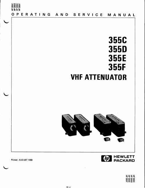
355C 355D 355E 355F
VHF ATTENUATOR
U
Printed: AU G UST 1980
\-
@@
rcE H"=&TJJ
If the attenuator must be connected to a
deuice with a potential gxeater than x5 Vdc, use a blocking capacitor.
Accessories Supplied
The 355E and 355F programmable attenuators are
trically. A procedure for checking electrical per-
formance is given under "Operator's Check" (see
PERFORMANCE TESTS). If the contents of the shipment are incomplete, if there is mechanical damage or defect, or if the instrument does not pass the electrical performance test, notify the nearest Hewlett-Packard office. If the shipping con-
部分A类件上下场对照表

不能替换
EGR/共轨
190000810930
铅封线
WG9716580021
电气接线盒总成(雅安小航)
不能替换
EGR/共轨
AZ9725584041
继电器安装板总成
WG9719582054
MCS开关(雅安小航)
不能替换
EGR/共轨
WG9100583058
车速传感器
WG9719582037
空载运行开关
橡胶软管210-150
不能替换
WG9719190100
空气滤清器总成
WG9725190200
空滤器总成
不能替换
WG9719190046
橡胶套管
WG9725190905
橡胶软管180
不能替换
WG9725190009
进气道总成II
WG9725190904
进气道(空滤器后)
不能替换
WG9719190090
出气软管
WG9725190906
橡胶软管
不能替换
AZ9719190095
空滤器支架总成
AZ9725190910
空滤器支架总成
不能替换
1280 550027
内螺纹销
AZ9003980026
软管卡箍-180/230 N05074
不能替换
1280 550028
内螺纹销
1280 550029
拉紧螺栓
一〉欧三共轨发动机(线束部分为自卸车、牵引车的,其它车型技术文件暂无):
AZ9716772004
EGR电磁阀附加电线束
WG9725580021
二极管总成(3A)(新天宇)
不能替换
Leviton ATLAS-X1 Cat 6A Component-Rated UTP QUICKP

Page 1 of 2APPLICATIONThe ATLAS-X1 Cat 6A Component-Rated UTP QUICKPORT Jack supports 10GBASE-T networks. The jack is part of a complete ATLAS-X1 Cat 6A UTP system, ideal for the most demanding mission-critical network applications. The connector supports emerging technologies and will easily adapt to network trends.SPECIFICATIONThe jack shall meet or exceed the requirements for channel and component-level electrical transmission performance as described in ANSI/TIA-568.2-D (Cat 6A), ISO/IEC11801-1 (Class E A ), and EN 50173-1 (Class E A ). The jack shall be compliant with ANSI/TIA-1096-A, c(UL)us Listed, and be independently verified for electrical transmission performance and power delivery. The jack body shall be made of die-cast zinc and all plastic components shall be made of high-impact, fire-retardant plastic rated UL 94V-0. The jack shall support tool-free termination and re-termination and shall not require a specialized termination tool. The jack wiring shall be universal to accommodate T568A and T568B wiring schemes. The jack shall be available in 13 colors; more than established by the ANSI/TIA-606-C standard. The jack shall be offered in standard and shuttered styles and select jacks shall be supplied with interchangeable icons. The jack shall be compliant with IEEE 802.3 PoE Type 1, 2, 3, 4 (100 watts max).DESIGN CONSIDERATIONS• Use in any QUICKPORT™ housing to support Cat 6A UTP connectivity in surface-mount, flush-mount, or modular furniture outlets and field-configurable panels• Can be used in conjunction with other QUICKPORT snap-in modules for voice/data/video applications over UTP , coax, and fiber• To identify ports, use different colored modules andicons for each application (full selection of ANSI/TIA-606 compatible colors, 13 available)• Robust housing and shutter protects the jack in harsh environmentsATLAS-X1™ Cat 6A Component-Rated UTP QUICKPORT™ Jack6AUJK-xx6, ICONS-ICxFEATURES• Independently tested and guaranteed to exceed all component, permanent link, and channel margins• Patented Retention Force Technology™ (RFT) protects against tine damage and increases system longevity • For Power over Ethernet, RFT maintains contact force between plug and jack, preventing arcing from intermittent disconnects• Unique design supports tool-free termination andre-termination and requires no specialized termination tool • Short jack design supports a wider range of applications (e.g. shallow boxes, enclosures, bend radius, etc.)• Terminates from 26 to 22 AWG solid or stranded conductors for use on various cable types• Robust IDCs can withstand 20 re-termination cycles and jack contacts are tested for 750 plug-mating cycles to ensure system longevity• Available in 13 ANSI/TIA-606-C compatible colors • Tested and approved for use in air-handling spaces (plenum rating) in accordance with UL Standard 2043• Select jacks available with interchangeable icons (voice, data, A/V, blank) for easy ID• Jack with internal shutter protects against dust and debris • Solid metal body dissipates 53% more heat than plastic, minimizing damage from excess heat in PoE applications • Tine geometry prevents arcing damage where plug and jack make contactSTANDARDS & REGULATIONS• ANSI/TIA-568.2-D (Cat 6A)• ISO/IEC 11801-1 (Cat 6A)• EN 50173-1 (Cat 6A)• ANSI/TIA-1096-A (formerly FCC Part 68)• IEC 60603-7 (includes IEC 60512-5-2)• IEC 60512-99-002• IEEE 802.3 PoE Type 1, 2, 3, 4 (100 watts max)• Cisco UPOE, UPOE+ (90 watts max)• Power over HDBaseT™ PoH (95 watts max)• c(UL)us Listed (UL 1863)• UL 2043 Plenum Certified • RoHS 3• ETL verified to meet the IEC 60512-99-002 standard for support of IEEE 802.3 Type 4 PoE (100 watt) applicationsCOUNTRY OF ORIGINUSA and Mexico (Contact Customer Service for details)6AUJK-xx6, ICONS-ICxUSANetwork Solutions Headquarters +1 (800) 722 2082 *******************Leviton Berk-Tek Cable : +1 (800) 237 5835 ************************Asia Pacific+852 3620 2602********************Canada+1 (800) 461 2002**********************Europe+44 (0) 1592 772124 **********************Latin AmericaMX: +52 (55) 2128 6286 LATAM: +52 (55) 2333 5963 *********************Middle East & Africa +971 (4) 247 9800 *******************NETWORK SOLUTIONS PRODUCTS ARE AVAILABLE WORLDWIDE IN OVER 100 COUNTRIES. VISIT US ONLINE AT /NS TO LEARN MORE.Page 2 of 2For further support information, visit /ns/support6AUJK-xx6, ICONS-ICx6AUJK-xx6, ICONS-ICxMECHANICAL SPECIFICATIONSDimensions:See belowMaterials: Jack Body: Die-cast zincSpring-Wire Contacts: High quality, copper-based alloy, plated with 50 microinches of gold for lowest contact resistance andmaximum life Temp. (Storage):Temp. (Installation): Temp. (Operating):Humidity (Max.):WARRANTY INFORMATIONFor Leviton product warranties, go to /ns/warrantyPART NUMBERDescriptionStandard Jack Jack with Shutter GREENPACK™12-Pack Standard Jack ATLAS-X1™ Cat 6A Component-Rated UTP QUICKPORT™ Jack, white 6AUJK-RW66AUJK-SW66AUJK-CW6ATLAS-X1 Cat 6A Component-Rated UTP QUICKPORT Jack, light almond 6AUJK-RT66AUJK-ST6—ATLAS-X1 Cat 6A Component-Rated UTP QUICKPORT Jack, ivory 6AUJK-RI66AUJK-SI6—ATLAS-X1 Cat 6A Component-Rated UTP QUICKPORT Jack, yellow 6AUJK-RY66AUJK-SY6—ATLAS-X1 Cat 6A Component-Rated UTP QUICKPORT Jack, orange 6AUJK-RO66AUJK-SO6—ATLAS-X1 Cat 6A Component-Rated UTP QUICKPORT Jack, crimson 6AUJK-RC66AUJK-SC6—ATLAS-X1 Cat 6A Component-Rated UTP QUICKPORT Jack, dark red 6AUJK-RR66AUJK-SR6—ATLAS-X1 Cat 6A Component-Rated UTP QUICKPORT Jack, purple 6AUJK-RP66AUJK-SP6—ATLAS-X1 Cat 6A Component-Rated UTP QUICKPORT Jack, blue 6AUJK-RL66AUJK-SL66AUJK-CL6ATLAS-X1 Cat 6A Component-Rated UTP QUICKPORT Jack, green 6AUJK-RV66AUJK-SV6—ATLAS-X1 Cat 6A Component-Rated UTP QUICKPORT Jack, gray 6AUJK-RG66AUJK-SG6—ATLAS-X1 Cat 6A Component-Rated UTP QUICKPORT Jack, black6AUJK-RE66AUJK-SE66AUJK-CE6ATLAS-X1 Cat 6A Component-Rated UTP QUICKPORT Jack, brown6AUJK-RB66AUJK-SB6—Green (V)Blue (L)Purple (P)Crimson (C)Dark Red (R)Orange (O)Yellow (Y)Black (E)Gray (G)Ivory (I)Light Almond (T)Brown (B)Color-matched icons (ICONS-ICx) can be ordered separately in 72-quantity packs.x = icon color。
GigaSPEED XL 3071E-B ETL Verified Category 6 U UTP
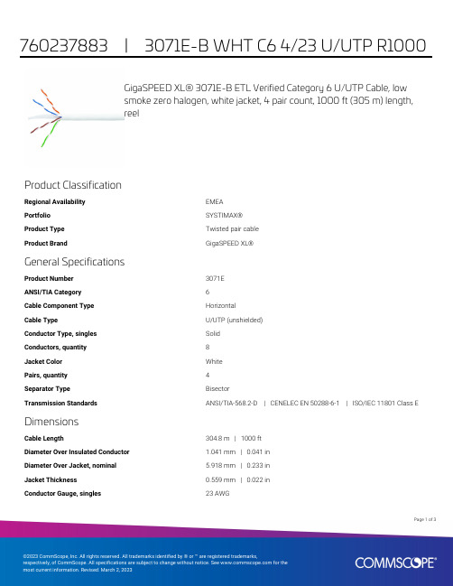
GigaSPEED XL® 3071E-B ETL Verified Category 6 U/UTP Cable, lowsmoke zero halogen, white jacket, 4 pair count, 1000 ft (305 m) length,reelProduct ClassificationRegional Availability EMEAPortfolio SYSTIMAX®Product Type Twisted pair cableProduct Brand GigaSPEED XL®General SpecificationsProduct Number3071EANSI/TIA Category6Cable Component Type HorizontalCable Type U/UTP (unshielded)Conductor Type, singles SolidConductors, quantity8Jacket Color WhitePairs, quantity4Separator Type BisectorTransmission Standards ANSI/TIA-568.2-D | CENELEC EN 50288-6-1 | ISO/IEC 11801 Class E DimensionsCable Length304.8 m | 1000 ftDiameter Over Insulated Conductor 1.041 mm | 0.041 inDiameter Over Jacket, nominal 5.918 mm | 0.233 inJacket Thickness0.559 mm | 0.022 inConductor Gauge, singles23 AWG13Page ofCross Section DrawingElectrical Specificationsdc Resistance Unbalance, maximum 5 %dc Resistance, maximum7.61 ohms/100 m | 2.32 ohms/100 ftDielectric Strength, minimum2500 VdcMutual Capacitance at Frequency 5.6 nF/100 m @ 1 kHzNominal Velocity of Propagation (NVP)70 %Operating Frequency, maximum300 MHzOperating Voltage, maximum80 VRemote Powering Fully complies with the recommendations set forth by IEEE 802.3bt (Type4) for the safe delivery of power over LAN cable when installed accordingto ISO/IEC 14763-2, CENELEC EN 50174-1, CENELEC EN 50174-2 or TIATSB-184-ASegregation Class cMaterial SpecificationsConductor Material Bare copperInsulation Material PolyolefinJacket Material Low Smoke Zero Halogen (LSZH)Separator Material PolyolefinPage of23Mechanical SpecificationsPulling Tension, maximum11.34 kg | 25 lbEnvironmental SpecificationsInstallation temperature0 °C to +60 °C (+32 °F to +140 °F)Operating Temperature-20 °C to +60 °C (-4 °F to +140 °F)Acid Gas Test Method EN 50267-2-3EN50575 CPR Cable EuroClass Fire Performance B2caEN50575 CPR Cable EuroClass Smoke Rating s1aEN50575 CPR Cable EuroClass Droplets Rating d0EN50575 CPR Cable EuroClass Acidity Rating a1Environmental Space Low Smoke Zero Halogen (LSZH)Smoke Test Method IEC 61034-2Packaging and WeightsCable weight38.097 kg/km | 25.6 lb/kftPackaging Type ReelRegulatory Compliance/CertificationsAgency ClassificationCENELEC EN 50575 compliant, Declaration of Performance (DoP) availableCHINA-ROHS Below maximum concentration valueISO 9001:2015Designed, manufactured and/or distributed under this quality management system REACH-SVHC Compliant as per SVHC revision on /ProductCompliance ROHSCompliantPage of33。
GE Industrial Solutions iVB Intelligent Embeded Po

• GB1984-2003
<High-voltage alternating current circuit breaker>
• GB/T11022-1999
Intelligent and Compact
Intelligence
Bring you reliable power solution
VCB is the most critical component for MV Switchgear iVB integrates conveniently for you
<Common specifications for high-voltage switchgear and control gear standards>
• DL/T 402-2007
<High-voltage alternating current circuit breakers>
• DL/T 403-2000
T : +86 21 3877 7888
Printing Code: IN201301B26EN
F : +86 21 3877 7600
© Copyright GE Industrial Solutions 2013
iVB Intelligent Embeded Pole Vacuum Circuit Breaker
Aux. contact
iTU
iTU Intelligent relay protection
ECE R4

E/ECE/324 )Add.3/Rev.3E/ECE/TRANS/505 )August 19, 2013STATUS OF UNITED NATIONS REGULATIONECE 4-00UNIFORM PROVISIONS CONCERNING THE APPROVAL OF:DEVICES FOR THE ILLUMINATION OF REAR REGISTRATION PLATES OFPOWER-DRIVEN VEHICLES AND THEIR TRAILERSIncorporating:Supplement 5 to the 00 series of amendments Date of Entry into Force: 11.02.96 Supplement 6 to the 00 series of amendments Date of Entry into Force: 15.01.97 Supplement 7 to the 00 series of amendments Date of Entry into Force: 18.01.98 Supplement 8 to the 00 series of amendments Date of Entry into Force: 13.01.00 Supplement 9 to the 00 series of amendments Date of Entry into Force: 26.08.02 Supplement 10 to the 00 series of amendments Date of Entry into Force: 26.02.04 Corr. 1 to Supplement 10 to the 00 series of amendments Dated: 04.03.04Corr. 2 to Supplement 10 to the 00 series of amendments Dated: 18.01.08Supplement 11 to the 00 series of amendments Date of Entry into Force: 04.07.06 Supplement 12 to the 00 series of amendments Date of Entry into Force: 02.02.07 Supplement 13 to the 00 series of amendments Date of Entry into Force: 11.07.08 Supplement 14 to the 00 series of amendments Date of Entry into Force: 15.10.08 Supplement 15 to the 00 series of amendments Date of Entry into Force: 09.12.10 Supplement 16 to the 00 series of amendments Date of Entry into Force: 15.07.13E/ECE/324 )Add.3/Rev.3E/ECE/TRANS/505 )August 19, 2013UNITED NATIONSAGREEMENTCONCERNING THE ADOPTION OF UNIFORM TECHNICAL PRESCRIPTIONS FORWHEELED VEHICLES, EQUIPMENT AND PARTS WHICH CAN BE FITTED AND/OR BE USED ON WHEELED VEHICLES AND THE CONDITIONS FOR RECIPROCAL RECOGNITION OF APPROVALS GRANTED ON THE BASIS OF THESE PRESCRIPTIONS(*) (Revision 2, including the amendments which entered into force on October 16, 1995)Addendum 3: Regulation No. 4-00Revision 3Incorporating all valid text up to:Supplement 10 to the original version of the Regulation - Date of entry into force:February 26, 2004Corrigendum 1 to Supplement 10 to the original version of the Regulation, subject of Depositary Notification C.N.180.2004.TREATIES-1 dated March 4, 2004Corrigendum 2 to Supplement 10 to the original version of the Regulation, subject of Depositary Notification C.N.1144.2007.TREATIES-1 dated January 18, 2008Supplement 11 to the original version of the Regulation - Date of entry into force: July 4, 2006 Supplement 12 to the original version of the Regulation- Date of entry into force: February 2, 2007 Supplement 13 to the original version of the Regulation- Date of entry into force: July 11, 2008 Supplement 14 to the original version of the Regulation- Date of entry into force: October 15, 2008 Supplement 15 to the original version of the Regulation- Date of entry into force: December 9, 2010Supplement 16 to the original version of the Regulation- Date of entry into force: July 15, 2013UNIFORM PROVISIONS CONCERNING THE APPROVAL OF DEVICESFOR THE ILLUMINATION OF REAR REGISTRATION PLATES OFPOWER-DRIVEN VEHICLES AND THEIR TRAILERS(*)Former title of the Agreement:Agreement Concerning the Adoption of Uniform Conditions of Approval and Reciprocal Recognition of Approval for Motor Vehicle Equipment and Parts, done at Geneva on March 20, 1958.REGULATION NO. 4-00UNIFORM PROVISIONS CONCERNING THE APPROVAL OF DEVICESFOR THE ILLUMINATION OF REAR REGISTRATION PLATESOF POWER-DRIVEN VEHICLES AND THEIR TRAILERSCONTENTSRegulationScope1. Definitions2. Application for Approval3. Markings4. ApprovalSpecifications5. General6. Colour of Light7. Incidence of the lightProcedure8. MeasuringCharacteristics9. Photometric10. Conformity of Production11. Penalties for Non-conformity of Production12. ProductionDefinit iv ely DiscontinuedProvisions13. Transitional14. Names and Addresses of Technical Services Conducting Approval Tests, and of Type ApprovalAuthoritiesANNEXESAnnex 1Arrangement of Approval MarksAnnex 2 CommunicationAnnex 3Measurement Points for Test PurposesAnnex 4Minimum Field of Visibility of the Surface to be IlluminatedAnnex 5Photometric Measurement of Lamps Equipped With Several Light Sources Annex 6Minimum Requirements for Conformity of Production Control Procedures Annex 7Minimum Requirements for Sampling by an InspectorREGULATION NO. 4-00UNIFORM PROVISIONS CONCERNING THE APPROVAL OF DEVICESFOR THE ILLUMINATION OF REAR REGISTRATION PLATESOF POWER-DRIVEN VEHICLES AND THEIR TRAILERSSCOPEThis Regulation applies to rear registration plate lamps for vehicles of Categories M, N, O, and T(1).1.DEFINITIONSFor the purpose of this Regulation:1.1."Rear registration plate lamp" means the device for the illumination of rear registrationplates, hereinafter called "illuminating device", which illuminates the rear registration plate byreflection. For the approval of this device, the illumination of the space to be occupied by theplate is determined.1.2.The definitions given in Regulation No. 48 and its series of amendments in force at the time ofapplication for type approval shall apply to this Regulation.1.3."Rear registration plate lamps of different types" means lamps which differ in suchessential respects as:(a) The trade name or mark;(b) The characteristics of the optical system, (levels of intensity, light distribution angles,category of filament lamp, light source module, etc.);1.4.References made in this Regulation to standard (étalon) filament lamp(s) and toRegulation No. 37 shall refer to Regulation No. 37 and its series of amendments in force at thetime of application for type approval.References made in this Regulation to standard (étalon) LED light source(s) and to Regulation No. 128 shall refer to Regulation No. 128 and its series of amendments in force atthe time of application for type approval.(1)As defined in the Consolidated Resolution on the Construction of Vehicles (R.E.3), document ECE/TRANS/WP.29/78/Rev.2, para.2. - /trans/main/wp29/wp29wgs/wp29gen/wp29resolutions.html.2.APPLICATION FOR APPROVALThe application for approval shall be submitted by the holder of the trade name or mark or by his duly accredited representative. It shall specify whether the device is intended to illuminate a wide plate (520 × 120mm), tall plate (340 × 240mm), plate for agricultural or forestry tractors (120 × 165mm), or any combination of those plates. At the choice of the applicant, it will also specify that the device may be fitted in more than one or a field of positions in relation to the space to be occupied by this registration plate; these different positions shall be indicated by the applicant in the communication form. It shall be accompanied by the following in respect of each type:(a) Drawings (three copies) in sufficient detail to permit identification of the type and showinggeometrically the position in which the illuminating device is to be fitted in relation to thespace to be occupied by the registration plate, and the outlines of the area adequatelyilluminated. The drawings must show the position intended for the approval number inrelation to the circle of the approval mark;(b) A brief technical description stating in particular, with the exception of lamps withnon-replaceable light sources:(i) The category or categories of filament lamp prescribed; this filament lampcategory shall be one of those contained in Regulation No. 37 and its series ofamendments in force at the time of application for type approval; and/or(ii) The category or categories of LED light source(s) prescribed; this LED light source category shall be one of those contained in Regulation No. 128 and its series ofamendments in force at the time of application for type approval.; and/or(ii i) The light source module specific identification code;(1)(c) Two samples, equipped with the lamp or lamps recommended.3.MARKINGSIlluminating devices submitted for approval must bear:3.1.The trade name or mark of the maker or manufacturer of the illuminating device;3.2. A space of sufficient size for the approval mark; this space shall be shown in the drawingsmentioned in Paragraph 2 a) above;3.3.In the case of lamps with non-replaceable light sources or light source module(s), the markingof rated voltage of the range of voltage, and the rated wattage.3.4.With the exception of lamps with non-replaceable light sources it must bear a clearly legibleand indelible marking indicating:(a) The category or categories of filament lamp(s) prescribed; and/or(b) The light source module specific identification code.(1)A light source is defined in ISO 7227:1987 "Road vehicles − Lighting and light-signalling devices − Vocabulary" as an emitterof visible and radiant energy.3.5.In the case of lamps with light source module(s), the light source module(s) shall bear:3.5.1.The trade name or mark of the applicant; this marking must be clearly legible and indelible;3.5.2.The specific identification code of the module; this marking must be clearly legible andindelible. This specific identification code shall comprise the starting Letters "MD" for "MODULE" followed by the approval marking without the circle as prescribed in Paragraph 4.4.1. below and, in the case several non-identical light source modules are used,followed by additional symbols or characters; this specific identification code shall be shown inthe drawings mentioned in Paragraph 2 a) above.The approval marking does not have to be the same as the one on the lamp in which the module is used, but both markings shall be from the same applicant.3.5.3.The marking of the rated voltage and rated wattage.4.APPROVAL4.1.If the two samples of a type of illuminating device submitted in accordance with Paragraph 2above satisfy the provisions of this Regulation, approval shall be granted.4.2.An approval number shall be assigned to each type approved. Its first two digits (at present 00for the Regulation in its original form) shall indicate the series of amendments incorporating themost recent major technical amendments made to the Regulation at the time of issue of theapproval. The same Contracting Party may not assign this number to another type of devicecovered by this Regulation, except in the case of an extension of the approval to a device differing only in the colour of the light emitted.4.3.Notice of approval or of extension or refusal of approval of a type of illuminating devicepursuant to this Regulation shall be communicated to the Parties to the 1958 Agreement applying this Regulation, by means of a form conforming to the model in Annex 2 to this Regulation.4.4.Every illuminating device conforming to a type approved under this Regulation shall, in additionto the markings referred to in Paragraphs 3 a) and c) above, bear an international approvalmark in conformity with Annex 1, consisting of:4.4.1. A circle surrounding the Letter "E" followed by a number identifying the country which hasgranted approval;(1)4.4.2.An approval number, in the vicinity of the circle;4.4.3.The following additional symbol: the Letter "L":4.4.4.The first two digits of the approval number which indicate the most recent series ofamendments to this Regulation may be placed in the vicinity of the additional Symbol L.4.5.The mark and symbols referred to in Paragraphs 4.4.1, 4.4.2. and 4.4.3. shall be indelible andshall be clearly legible even when the illuminating device is mounted on the vehicle.(1)The distinguishing numbers of the Contracting Parties to the 1958 Agreement are reproduced in Annex 3 to the Consolidated Resolution on the Construction of Vehicles (R.E.3), document ECE/TRANS/WP.29/78/Rev.2/Amend.3 -/trans/main/wp29/wp29wgs/wp29gen/wp29resolutions.html4.6.When two or more lamps are part of the same unit of grouped, combined or reciprocallyincorporated lamps, approval is granted only if each of these lamps satisfies the requirements of this Regulation or of another Regulation. Lamps not satisfying any one of those Regulations shall not be part of such a unit of grouped, combined or reciprocally incorporated lamps.4.6.1.Where grouped, combined or reciprocally incorporated lamps comply with the requirements ofseveral Regulations, a single international approval mark may be applied, consisting of a circle surrounding the Letter "E" followed by the distinguishing number of the country which has granted the approval, an approval number and, if necessary, the required arrow. This approval mark may be placed anywhere on the grouped, combined or reciprocally incorporated lamps provided that:4.6.1.1. It is visible after their installation;4.6.1.2. No part of the grouped, combined or reciprocally incorporated lamps that transmits light can beremoved without at the same time removing the approval mark.4.6.2.The identification symbol for each lamp appropriate to each Regulation under which approvalhas been granted, together with the corresponding series of amendments incorporating the most recent major technical amendments to the Regulation at the time of issue of the approval, shall be marked:4.6.2.1. Either on the appropriate light-emitting surface;4.6.2.2. Or in a group, in such a way that each lamp of the grouped, combined or reciprocallyincorporated lamps may be clearly identified (see three possible examples in Annex 1).4.6.3.The size of the components of a single approval mark shall not be less than the minimum sizerequired for the smallest of the individual marks by a Regulation under which approval has been granted.4.6.4.An approval number shall be assigned to each type approved. The same Contracting Partymay not assign the same number to another type of grouped, combined or reciprocally incorporated lamps covered by this Regulation.4.6.5. The approval marking shall be clearly legible and indelible. It may be placed on an inner orouter part (transparent or not) of the device which cannot be separated from the transparent part of the device emitting the light. In any case the marking shall be visible when the device is fitted on the vehicle or when a movable part such as the hood or boot lid or a door is opened. 4.7.Annex 1 gives examples of arrangements of approval marks for a single lamp (Figure 1) andfor grouped, combined or reciprocally incorporated lamps (Figure 2) with all the additional symbols referred to above.5.GENERAL SPECIFICATIONSEach device shall satisfy the provisions of Paragraph 9(1)5.1.The devices for the illumination of rear registration plates shall be so constructed that the wholesurface of the plate will be visible within the angles given in Annex 4.5.2.All measurements shall be made with the standard uncoloured or coloured light source of thecategory prescribed by the manufacturer, supplied with the voltage:(a) In the case of filament lamp(s), that is necessary to produce the reference luminous fluxrequired for that category of filament lamp;(b) In the case of LED light source(s) of 6.75V, 13.5V or 28.0V, the luminous flux valueproduced shall be corrected. The correction factor is the ratio between the objectiveluminous flux and the value of the luminous flux found at the voltage applied.All measurements on the devices with non-replaceable light sources shall be made at 6.75V,13.5V or 28.0V respectively.5.3.In the case of light sources supplied by a special power supply, the above test voltages shall beapplied to the input terminals of that power supply. The test laboratory may require from manufacturer the special power supply needed to supply the light sources.5.4.For any rear registration plate illuminating device, except those equipped with filament lamp(s),the luminance values measured after one minute and after 30 minutes of operation shall comply with the minimum requirements.The luminance distribution after one minute of operation can be calculated by applying at each test point the ratio of luminance values measured in one point after one minute and after30 minutes of operation.5.5.In the case of light source modules, it shall be checked that:5.5.1.The design of the light source module(s) shall be such as:(a) That each light source module can only be fitted in no other position than the designatedand correct one and can only be removed with the use of tool(s).(b) If there are more than one light source module used in the housing for a device, lightsource modules having different characteristics cannot be interchanged within the samelamp housing.5.5.2.The light source module(s) shall be tamperproof.5.5.3. A light source module shall be so designed that regardless of the use of tool(s), it shall not bemechanically interchangeable with any replaceable approved light source.(1)These specifications are such as to ensure good visibility if the inclination of the registration plate does not exceed 30° on either side of the vertical.5.6.In the case of replaceable light source(s):5.6.1.Any category or categories of light source(s) approved according to Regulation No. 37 and/orRegulation No. 128 may be used, provided that no restriction on the use is made in Regulation No. 37 and its series of amendments in force at the time of application for type approval or in Regulation No. 128 and its series of amendments in force at the time of application for type approval.5.6.2.The design of the device shall be such that the light source can not be fixed in any otherposition but the correct one.light source holder shall conform to the characteristics given in IEC Publication 60061. The 5.6.3. Theholder data sheet relevant to the category of light source used, applies.6. COLOUR OF LIGHTThe light of the lamp used in the illuminating device must be sufficiently colourless not to cause any appreciable change in the colour of the registration plate.7.INCIDENCE OF THE LIGHTThe manufacturer of the illuminating device shall specify one or more or a field of positions in which the device is to be fitted in relation to the space for the registration plate; when the lamp is placed in the position(s) specified by the manufacturer the angle of incidence of the light on the surface of the plate does not exceed 82° at any point on the surface to be illuminated, this angle being measured from the extremity of the device's illuminating area which is furthest from the surface of the plate. If there is more than one illuminating device, the foregoing requirement shall apply only to that part of the plate intended to be illuminated by the device concerned.When the device has one outer edge of the illuminating surface that is parallel to the surface of the registration plate, the extremity of the illuminating surface of the device which is furthest from the surface of the plate is the middle point of the edge of the illuminating surface, which is parallel to the plate and is furthest from the surface of the plate.The device must be so designed that no light is emitted directly towards the rear, with the exception of red light if the device is combined or grouped with a rear lamp.8.MEASURING PROCEDURELuminance measurements shall be made on a diffuse colourless surface with known diffuse reflection factor(1). The diffuse colourless surface shall have the dimensions of the registration plate or the dimension exceeding one measuring point. Its centre shall be placed in the centre of the positions of the measuring points.This diffuse colourless surface(s) shall be placed in the position normally occupied by the registration plate and 2mm in front of its holder.Luminance measurements shall be made perpendicularly to the surface of the diffuse colourless surface with the tolerance of 5° in each direction at the points shown in Annex 3 to this Regulation, each point representing a circular area 25mm in diameter. The measured luminance shall be corrected for the diffuse reflection factor 1.0.(1)CIE Publication No. 17 − 1970, Paragraph 45-20-040.9. PHOTOMETRIC CHARACTERISTICSAt each of the points of measurement shown in Annex 3, the illuminance B shall be at least equal to 2.5cd/m 2.The gradient of the luminance between the values B 1 and B 2, measured at any two Points 1 and 2 selected from among those mentioned above, shall not exceed 2 x Bo/cm, Bo being the minimum luminance measured at the various points, that is to say:cm /Bo 2cmin 21ce tan dis B B 12×≤−−10. CONFORMITY OF PRODUCTIONThe conformity of production procedures shall comply with those set out in the Agreement, Appendix 2 (E/ECE/324-E/ECE/TRANS/505/Rev.2), with the following requirements:10.1. Devices for the illumination of rear registration plates (henceforth called devices), approvedunder this Regulation shall be so manufactured as to conform to the type approved by meeting the requirements set forth in Paragraphs 5, 6 and 9 above. If there is more than one device necessary, then in the following text a device means a set of devices.10.2. The minimum requirements for conformity of production control procedures set forth in Annex 6to this Regulation shall be complied with.10.3. The minimum requirements for sampling by an inspector set forth in Annex 7 to this Regulationshall be complied with.10.4. The Authority which has granted type approval may at any time verify the conformity controlmethods applied in each production facility. The normal frequency of these verifications shall be once every two years.11. PENALTIES FOR NON-CONFORMITY OF PRODUCTION11.1. The approval granted in respect of an illuminating device pursuant to this Regulation may bewithdrawn if the requirements laid down above are not complied with.11.2. If a Party to the Agreement which applies this Regulation withdraws an approval it haspreviously granted, it shall forthwith notify the other Contracting Parties applying this Regulation thereof by means of a communication form conforming to the model in Annex 2 to this Regulation.12. PRODUCTION DEFINIT IV ELY DISCONTINUEDIf the holder of the approval completely ceases to manufacture an illuminating device under this Regulation, he shall inform thereof the Authority which granted the approval. Upon receiving the relevant communication that Authority shall inform the other Parties to the Agreement which apply this Regulation thereof by means of a communication form conforming to the model in Annex 2 to this Regulation.13.TRANSITIONAL PROVISIONS13.1. Rear registration plate illuminating devices not equipped with filament lamps.13.1.1.As from the date of entry into force of Supplement 8, no Contracting Party applying thisRegulation shall refuse to grant approvals under this Regulation as amended by Supplement 8.13.1.2.As from 36 months after the date of entry into force of Supplement 8, Contracting Partiesapplying this Regulation shall grant approvals only if the type of devices as described in Paragraph 13.1. above meets the requirements of this Regulation as amended by Supplement 8.13.1.3. Contracting Parties applying this Regulation shall not refuse to grant extensions of approvals tothe preceding series of amendments to this Regulation.13.1.4.Contracting Parties applying this Regulation shall continue to grant approvals to those types ofdevices as described in Paragraph 13.1. above which comply with the requirements of this Regulation as amended by the preceding series of amendments during the 36 months' periodwhich follows the date of entry into force of Supplement 8.13.2.Fitting of rear registration plate illuminating devices described in Paragraph 13.1. above on avehicle.13.2.1.As from the date of entry into force of Supplement 8, no Contracting Party applying thisRegulation shall prohibit the fitting on a vehicle of devices described in Paragraph 13.1. aboveapproved under this Regulation as amended by Supplement 8.13.2.2.Contracting Parties applying this Regulation shall continue to allow the fitting on a vehicle ofdevices described in Paragraph 13.1. above approved to this Regulation as amended by the preceding series of amendments during the 48 months' period which follows the date of entryinto force of Supplement 8.13.2.3.Upon the expiration of a period of 48 months after the date of entry into force of Supplement 8,Contracting Parties applying this Regulation may prohibit the fitting of devices described in Paragraph 13.1. above which do not meet the requirements of this Regulation as amended bySupplement 8 on a new vehicle for which type approval or individual approval was granted more the 24 months after the entry into force of Supplement 8 to this Regulation.13.2.4.Upon expiration of a period of 60 months after the date of entry into force of Supplement 8,Contracting Parties applying this Regulation may prohibit the fitting of devices as described inParagraph 13.1. above which do not meet the requirements of this Regulation as amended bySupplement 8 on a new vehicle first registered more than 60 months after the date of entry intoforce of Supplement 8 to this Regulation.14. NAMES AND ADDRESSES OF TECHNICAL SERVICES CONDUCTING APPROVAL TESTSAND OF TYPE APPROVAL AUTHORITIESThe parties to the Agreement which apply this Regulation shall communicate to the Secretariatof the United Nations the names and addresses of the Technical Services conducting approvaltests and of the Type Approval Authorities which grant approval and to which forms certifying approval or refusal or withdrawal or approval, issued in other countries, are to be sent.ANNEX 1ARRANGEMENT OF APPROVAL MARKSModel Aa = 5mm minFigure 1(Marking For Single Lamps)The device bearing the approval mark shown above is a device for the illumination of a vehicle's rear registration plate (L) approved in the Netherlands (E 4) pursuant to Regulation No. 4 under approval number 2439. The approval number indicates that the approval was granted in accordance with the requirements of Regulation No. 4 in its original form or as amended by the respective supplements to theRegulation in its original form, as the case may be.Model BModel CModel DFigure 2Simplified Marking For Grouped, Combined or ReciprocallyIncorporated Lamps(The vertical and horizontal lines schematize the shape of the light-signalling device. These are not part of the approval mark).Note:The three examples of approval marks, Models B, C and D represent three possible variants of the marking of a lighting device when two or more lamps are part of the same unit of grouped, combined or reciprocally incorporated lamps. This approval mark shows that the device was approved in the Netherlands (E 4) under approval number 3333 and comprising:A retro reflector of Class IA approved in accordance with the 02 series of amendments to Regulation No. 3;A rear direction indicator of Category 2a approved in accordance with the 01 series of amendments to Regulation No. 6;A red rear position lamp (R) approved in accordance with the 01 series of amendments to Regulation No. 7;A rear fog lamp (F) approved in accordance with Regulation No. 38 in its original form;A reversing lamp (AR) approved in accordance with Regulation No. 23 in its original form;A stop lamp with two levels of illumination (S2) approved in accordance with the 01 series of amendments to Regulation No. 7;A rear registration plate illuminating device (L) approved in accordance with Regulation No. 4 in its original form.Model EMD E3 17325Figure 3Light Source ModulesThe light source module bearing the identification code shown above has been approved together with a lamp approved in Italy (E3) under approval number 17325.。
卡林技术公司产品说明书

UL Recognized UL Standard 1077Component Recognition Program as Protectors,Supplementary (Guide QVNU2,File E75596)UL Standard 508Switches,Industrial Control (Guide NRNT2,File E148683)CSA CertifiedComponent Supplementary Protector under Class 3215 30,FIle 047848 0 000CSA Standard C22.2 No. 235VDE CertifiedEN60934,VDE 0642 under File No.10537Agency CertificationsNotes for T able A:1DC and 1Ø 277 Volt ratings are 1 or 2 poles breaking. 3Ø Ratings are 3 poles breaking.2 Requires branch circuit backup with a UL LISTED Type K5 or RK5 fuse rated 15A minimum and no more than 4 times full load amps not to exceed 150A for 250 Volt rating and 125A for 277and 480 Volt ratings.3 UL Recognition and CSA Certification at 480 Volts refers to 3 and 4 pole versions, used only in a 3Ø wye connected circuit or 2 pole versions connected with 2 poles breaking 1Ø and backedup with series fusing per note 2.Table A:Lists UL Recognized and CSA and VDE Certified configurations and performance capabilities as a Component Supplementary Protector.ElectricalCURRENT RA TINGCIRCUITMAX FULL LOAD WITH WITHOUT (Inc) WITH (Icn) WITHOUTCONFIGURA TIONRA TINGFREQUENCYPHASEAMPSBACKUP FUSEBACKUP FUSEBACKUP FUSEBACKUP FUSE65DC ---0.02 - 50 ---500050001500125/25050/60 1 and 30.02 - 50 ---3000 --- ---25050/60 1 and 30.02 - 505000 ---5000150027750/6010.02 - 505000 --- --- ---480 Y 50/60 1 and 30.02 - 305000---------65DC ---0.02 - 5025050/60 1 and 30.02 - 5027750/6010.02 - 50480 Y50/6030.02 - 30480 Y 50/6010.02 - 30SWITCH ONL Y UL / CSAVDED-SERIES TABLE A: COMPONENT SUPPLEMENTARY PROTECTORVOLT AGEINTERRUPTING CAPACITY (AMPS)SERIESDesigned for snap-on-back panel rail mounting on either a 35mm x 7.5mm, or a 35mm x 15mm Symmetrical Din Rail,allowing rapid and simple mounting and removal of the breaker.It features recessed, wire-ready, touch-proof, shock-resistant ter-minals, suitable for automatic screwdriver assembly, as well as "Dead Front" construction characteristics.Available with a Visi-Rocker two-color actuator, which can be specified to indicate either the ON or the TRIPPED/OFF mode,or solid color rocker or handle type actuators. All actuator types fit in the same industry standard panel cutouts.0.02 - 50 amps, up to 480 VAC or 65 VDC, 1 - 4 poles (Handle),1 - 3 poles (Rocker), with a choice of time delays.Number of PolesRocker Type: 1-3; Handle Type: 1-4 Internal Circuit Config. Switch Only and Series Trip with cur-rent or voltage trip coils.WeighApproximately 128 grams/pole (Approximately 4.57 ounces/pole)Standard Colors Housing - Black; Actuator - See Ordering Scheme.MountingMounts on a standard 35mmSymmetrical DIN Rail (35 x 7.5 or 35x 15mm per DIN EN5002).MechanicalElectricalPhysicalEndurance10,000 ON-OFF operations @ 6 per minute; with rated Current and Voltage.Trip FreeAll D-Series Circuit Breakers will trip on overload,even when actuator is forcibly held in the ON position.Trip IndicationThe operating actuator moves posi-tively to the OFF position when an overload causes the breaker to trip.Designed and tested in accordance with requirements of specifi-cation MIL-PRF-55629 & MIL-STD-202 as follows:Shock Withstands 100 Gs,6ms,sawtoothwhile carrying rated current per Method 213,Test Condition "I".Instantaneous and ultra-short curves tested @ 90% of rated current.Vibration Withstands 0.060" excursion from10-55 Hz,and 10 Gs 55-500 Hz,at rated current per Method 204C,Test Condition A. Instantaneous and ultra-short curves tested at 90% of rated current.Moisture Resistance Method 106D,i.e.,ten 24-hourcycles @ + 25°C to +65°C,80-98%RH.Salt Spray Method 101,Condition A (90-95%RH @ 5% NaCl Solution,96 hrs).Thermal Shock Method 107D,Condition A (Fivecycles @ -55°C to +25°C to +85°C to +25°C).Operating Temperature -40°C to +85°CEnvironmental020 0.0200250.0250300.0300500.050075 0.0750800.0800850.0852100.1002150.1502200.2002250.2502300.3002350.3502400.4002450.450250 0.5002550.5502600.6002650.6502700.7002750.7502800.8002850.850410 1.000512 1.250413 1.300414 1.400415 1.500517 1.750420 2.000522 2.250425 2.500527 2.750430 3.000532 3.250435 3.500436 3.600440 4.000445 4.500547 4.750450 5.000455 5.500460 6.000465 6.5004707.0005727.2504757.5004808.0004858.5004909.0004959.500610 10.00071010.50061111.00071111.50061212.00071212.50061313.00061414.000615 15.00061616.00061717.00061818.00061919.00062020.00062121.00062222.000623 23.00062424.00062525.00062626.00062727.00062828.00062929.00063030.00063232.00063535.00064040.00064545.00065050.000A06 6 DC, 5 DC A1212 DC, 10 DC A1818 DC, 15 DC A2424 DC, 20 DC A3232 DC, 25 DC A4848 DC, 40 DC A6565 DC, 55 DC J06 6 AC, 5 AC J1212 AC, 10 AC J1818 AC, 15 ACJ2424 AC, 20 AC J4848 AC, 40 AC K20120 AC, 65 AC L40240 AC, 130 AC10Agency Approval8Actuator Color8 ACTUATOR COLOR & LEGEND Actuator orVisi-Color Marking: Marking Color: Single Color Visi-Rocker Color:I-O ON-OFF Dual Rocker/Handle (Actuator Black)8White A B 1Black White Black C D 2White n/a Red F G 3White Red Green H J 4White Green Blue K L 5White Blue Y ellow M N 6Black Y ellow Gray P Q 7Black Gray OrangeRS8Black Orange10 AGENCY APPROVAL C UL Recognized & CSA Certified D VDE Certified, UL Recognized & CSA Certified9 MOUNTING/VOLTAGEMOUNTING STYLE VOLTAGE Threaded Insert 16-32 x 0.195 inches< 300C 96-32 X 0.195 inches ≥300 2ISO M3 x 5mm< 300D 9ISO M3 x 5mm ≥3007 TERMINAL1#10 Screw & Pressure Plate for Direct Wire Connection 2#10 Screw without Pressure Plate3 POLES 1One2Two 3Three4Four5 FREQUENCY & DELA Y 03DC 50/60Hz, Switch Only 105DC Instantaneous 11DC Ultra Short 12DC Short 14DC Medium 16DC Long20550/60Hz Instantaneous 2150/60Hz Ultra Short 2250/60Hz Short 2450/60Hz Medium2650/60Hz Long32DC, 50/60Hz Short 34DC, 50/60Hz Medium 36DC, 50/60Hz Long42650/60Hz Short, Hi-Inrush 44650/60Hz Medium, Hi-Inrush 46650/60Hz Long, Hi-Inrush 527DC, Short,Hi-Inrush 547DC,Medium, Hi-Inrush 567DC, Long, Hi-Inrush4 CIRCUITA0 Switch Only (No Coil) 4B0Series Trip (Current)C0Series Trip (Voltage)1 SERIES D6Current Rating4Circuit3Poles2Actuator9Mounting/Voltage7Terminal5Frequency & Delay1SeriesNotes:1 Handle breakers available up to four poles. Rocker breakers available up to three poles.2Actuator Code:A: Multi-pole units factory assembled with common handle tie.B: Handle location as viewed from front of breaker:2 pole - left pole3 pole - center pole4 pole - two handles at center poles3Multipole rocker breakers have one rocker per breaker, as viewed from the front of thepanel. Two pole - left pole. Three pole - center pole 4≤30A, select Current Rating code 630. 31-50A, select Current Rating code 650.5Voltage coil only available with delay codes 10 & 20.6Available to 50A max with circuit code BO only.7Available to 50A (UL/CSA), 30A (VDE) with circuit code BO only.8Color shown is visi and legend with remainder of rocker black.9≥300V: Three pole breaker 3Ø or 2 pole breaker 1Ø, UL/CSA limited to 30 FLA max.10VDE Approval requires Dual (I-O, ON-OFF) or I-O markings6 CURRENT RATING (AMPERES)OR VOLTAGE COIL (VOLTS, MIN. TRIP RATING)5P0LE 3P0LE 2P0LE 1SERIES TRIP (2 TERM'S.)LINELINEROCKER ACTUATOR INDICATE "ON"HANDLE ACTUATORSWITCH ONL Y (2 TERM'S.)#10-32 SCREW AND PRESSURE PLA TE PER TERMINAL"MULTI-POLE IDENTIFICATION SCHEMENotes:1All dimensions are in inches [millimeters].2T olerance ±.015 [.38] unless otherwise specified.3-POLE(DF3) 3-POLE(DC3)REMOVALASSEMBL YNotes:1All dimensions are in inches [millimeters].2T olerance ±.015 [.38] unless otherwise specified.3Dimensions apply to all variations shown. Notice that circuit breaker line and load termi-nal orientation on indicate OFF is opposite of indicate ON.4For pole orientation with horizontal legend, rotate front view clockwise 90°.Notes:1All dimensions are in inches [millimeters].2T olerance ±.010 [.25] unless otherwise specified.。
GE关键零部件可靠性测试标准

GE关键零部件可靠性测试标准GE关键零部件可靠性测试标准1范围本标准规定了房间空气调节器上关键零部件的可靠性测试标准。
本标准适用于所有销售给GE的除湿机产品。
2规范性引用文件下列文件中的条款通过本标准的引用而成为本标准的条款。
凡是注日期的引用文件,其随后所有的修改单(不包括勘误的内容)或修订版均不适用于本标准,然而,鼓励根据本标准达成协议的各方研究是否可使用这些文件的最新版本。
凡是不注日期的引用文件,其最新版本适用于本标准。
152B2233P001 Appendix M GE零部件可靠性测试方法SI209066S012 RAC fan qualification procedures GE风轮风叶可靠行认可程序SI209066S015 Room air conditioner fan motor GE风机可靠性测试标准ETP910C001-Rev6 GE产品可靠性试验要求E9C26S、F50L008S、F50L012S、F50LD19 GE表面处理类标准3定义本标准采用下列定义。
3.1GE除湿机销售给GE客户的除湿机产品。
3.2关键零部件指GE除湿机上的压缩机、风轮风叶、风机、控制按键、风机电容、压缩机电容、万向轮、微动开关、感温器、湿度传感器、PCB板(变压器)、继电器等对产品性能有重要影响、作用的零部件。
4风轮风叶可靠性测试在现有企业标准(空调风机用风轮风叶技术条件)的基础之上,增加下列测试项目。
5异步电机可靠性测试5.1电机应符合企标《单相电容运转异步电动机》的要求。
5.2测试方法5.2.1测试环境:电机的测试环境温度为大于35℃小于40℃, 湿度大于50%.5.2.2运行条件:测试电压为正常的家用电115V+10%/-15%,60+/-1HZ.匹配电容为6UF/250VAC电机电容.5.2.3负载:在挑选风叶时,风叶的不平衡度应该是正常最大不平衡的2到4倍.不平衡角度可以通过加平衡块来改变.(挑选方法:测试出三十个风叶的不平衡度,用公式计算,负载应加的不平衡度=[三十个风叶的不平衡度的平均值+3×三十个风叶的不平衡度的方差] ×3),也即说每个风叶应有的不平衡应等于最接近平均值的风叶加上负载应加的不平衡度后所拥有的不平衡度.5.2.4测试数量: 50台5.2.5测试周期:每一个电机测试天.5.2.6测试步骤:1.检测电机表面有无油污,轴承处有无漏油,并把没有发生上述现象的电机编好号;2.在常温下(20℃±3℃),测试已经编号的电机的主副相电阻,并把主副相电阻,测试温度记录下来.电阻不能超出电机技术规范的要求!同时所用电容的容量必须测试并记录.并与匹配的电机的编号一一对应编号;3.测试每一个电机的绝缘电阻,并记录;4.经过上述检测过的电机拿到静音室测试空载噪音. 在额定测试电压下,用手拿着电机,在离电机轴2英尺的地方用耳听.务必确定所有电机的噪音水平保持一致.如有异常噪音或空载输入功率有异常的电机不得进行下一步测试;5.测试电机的振动不能超出电机技术规范的要求.有超出的电机不得进行下一步测试;6.把电机固定在工装上,电机的安装位置为,电机的轴向与地面保持水平,且垂直于工装,电机与电机之间的距离为负载直径的2倍;7.应记录的参数:电机的运行速度,电机的运行功率,电机的噪音,电机的运行电流,电机的运行温度,环境的温度和湿度,上述参数必须每天都测试.电机的最小起动电压每一周须测试一次.电机在运行时,每隔24小时必须观察电机的振动情况并记录.测试结束后必须测量每一个电机的绝缘电阻并记录.电容的容量也必须测试并记录(测试结束后);8.在可靠性测试完后,任何与其他同类电机相比有异音的电机必须用0到20KHZ频带宽的噪声测试仪进行对比测试分析.方法如下:用弹性皮带把电机(轴向朝上)悬挂起来,离地面大约30CM,在电机轴的正上方15CM处安装一个麦克风,在测试过程中必须把电机风叶拆下.并记录其分贝值且把频谱图保存为文件;5.3判定标准如果出现下述情况则认为测试不合格:(1)电机接触不良或者主﹑副相开路.(2)噪音超出原始热态值的5%.(3)轴承漏油,通过目测.(4)轴的振动超出技术要求.(5)输入功率超出原始热态值的5%.(6)速度的变换超出原始热态值的5%.(7)电机表面有无油污.5.4设备要求所有测试设备必须在校对的有效期内,并且在每天测试记录时必须记录下所用仪器的编号和校对日期.5.5补充说明该测试项目为型式试验,不列入进货检验测试项目。
- 1、下载文档前请自行甄别文档内容的完整性,平台不提供额外的编辑、内容补充、找答案等附加服务。
- 2、"仅部分预览"的文档,不可在线预览部分如存在完整性等问题,可反馈申请退款(可完整预览的文档不适用该条件!)。
- 3、如文档侵犯您的权益,请联系客服反馈,我们会尽快为您处理(人工客服工作时间:9:00-18:30)。
– Vehicles with an internal combustion engine can be forced by the manufacture to operate, but this condition cannot be reproduced in a roadside check. – Forcing a non-normal operating mode of the vehicle would be viewed as “Test Detection” in other circumstances.
Doug Moore ISO WG42 Convener 49th GRB February, 2009
Background
Stationary noise testing in ECE R51 (ISO 5130) was included to provide a mechanism for in-use compliance testing of vehicle noise emissions. The implicit technical assumption for using stationary noise testing was some correlation to actual on-road vehicle noise emission.
Informal Document No. GRB-49-06 (49th GRB, 16-18 February 2009, agenda item 3(a))
ECE R51 (ISO 5130) Stationary Noise Testing of Advanced Technology Vehicles
Note: This presentation is to inform GRB on technical issues related to stationary noise testing. Technical developments in vehicle propulsion systems result in the situation where certain advanced technology vehicles have no valid test mode. ISO seeks the advice of GRB and makes a suggestion for accounting for such vehicles.
Stationary Noise Testing of Advanced Technology Vehicles
Issue: Some Advanced Technology Vehicles have no engine RPM at stationary conditions during normal operation.
– Evolutionary changes in vehicle technology have reduced this correlation. (engine protection, new exhaust system configurations) The latest updates to ISO 5130 addressed many of these issues. – Revolutionary changes in vehicle technology obsolete this correlation. (electric propulsion, fuel cells, stop-start operation, hybrids, etc.)
Resulssible.
Proposed Solution: Exempt such vehicles from stationary testing
Long Term
GRB (ISO) will need to consider the methods of in-use testing suitable for future technology vehicles.