Robustness Testing of a Distributed Simulation Backplane
robust standard errors

robust standard errorswhen a linear-regression model’s assumption of uniformity of variance, also known as homoscedasticity, is violated, robust standard errors can be used. heteroscedasticity implies that the oute’s varianceis not constant across observations, which is a phenomenon known as heteroscedasticity.why do we use robust standard errors for heteroskedasticity?to fit a model that does contain heteroskedastic residuals, heteroskedasticity-consistent standard errors are used. huber (1967) proposed the first such approach, and since then, cross-sectional data, time series data, and garch estimation procedures have been improved.should i use a robust standard error method?as a result, the robust standard errors are safe touse (especially when there is a large sample size). even if there is no heteroskedasticity, the robust standard errors will be replaced by conventional ols standard errors. as a result, even under homoskedasticity, robust standard errors are acceptable.how are robust standard errors calculated?the square root of the elements on the covariance matrix’s diagional is equal to the huber-white robust standard errors. the squared residuals from the ols method are represented by the elements of s. these standard errors are referred to as heteroskedasticity-consistent (hc) standards.is it important to use standard errors?standard error is important because it allows you to estimate how well your sample data represents theentire population. increase the sample size to reduce standard error.the best way to minimize sampling bias is to use a large, random sample.why do robust standard errors have a better reputation?in social sciences, where the structure of variationis unknown, robust standard errors are useful, but in physical sciences, where the amount of variation for each observation is the same, they are usually avoided. robust standard errors are usually larger than non-robust standard errors, but they can also be smaller.what exactly is a high-response standard error?if a regression estimator is still reliable in the presence of outliers, it is said to be robust. on the other hand, if regression errors are autocorrelatedand/or heteroskedastic, it is said to be robust ifthey are still reliable.why do we use standard error clusters?the authors argue that clustering standard errors can be caused by two factors: a sampling design reason, which arises when you sample data from a population using clustered sampling and want to say something about the larger population; and an experimental design reason, which arises when some people’s assignment mechanism is altered.why are clustered standard errors more mon?the cluster-robust standard errors in such did examples with panel data can be significantly larger than the default because both the regressor and the errors are highly correlated within the cluster. this serial correlation can result in a significant difference between cluster-robust and default standard errors.is it possible to reduce robust standard errors by a factor of two?the lesson we can take away from this is that standard errors are not a panacea. because of the small sample bias we’ve discussed and the higher sampling variance of these standard errors, they can be smaller than ols standard errors. in finite samples, standard error estimates may be biased.what do you learn from robust standard errors?under heteroscedasticity, “robot” standard errors is a technique that obtains unbiased standard errors of ols coefficients. remember that heteroscedasticity is a violation of the gauss markov assumptions required to make ols the best linear unbiased estimator (blue).what are the consequences of cluster-robust standard errors?standard errors in clusters are designed to allow for correlation between cluster observations.robust standard errors 12when data is contaminated with outliers or influential observations, robust regression is an alternative to least squares regression, and it can also be used to detect influential observations.what is the best way to interpret standard error?the value for the standard error of the mean indicates how far sample means from the population mean are likely to fall using the original measurement units. larger values, once again, indicate larger distributions.we know that the average difference between a sample mean and a population mean is 3 for a sem of 3.what level should standard errors be clustered at?instead, we show that standard errors should be clustered at the pair level by researchers. we demonstrate that those results extend to stratified experiments with only a few units per strata using simulations.robust standard errors 15state in their conclusion that if the sampling process and treatment assignment aren’t clustered, you shouldn’t cluster standard errors, even if clustering alters your standard errors. in the following three possible cases, clustering will yield approximately correct standard errors.is it better to use robust regression?robust regression is a less restrictive alternative to least squares regression. when outliers are present in the data, it provides much better regression coefficient estimates.in least squares regression, outliers violate the assumption of normally distributed residuals.what exactly do strong results entail?the term robust or robustness in statistics refers to the strength of a statistical model, tests, or procedures based on the specific conditions of the statistical analysis that a study hopes to achieve. to put it another way, a reliable statistic is resistant to results errors.is heteroskedasticity robust to regression?we also require a robust heteroskedastic regression method that is patible with the form of heteroskedasticity specified. ordinary least squares (ols) and “heteroskedastic robust” standard errors are used in a very general method (white, 1980).in statistics, what is a robust test?in the case of tests, robustness refers to the test’s validity even after such a change. to put it another way, whether or not the oute is significant is only meaningful if the test’s assumptions are met.the test is said to be robust when such assumptions are relaxed (i.e. not as important).what is the best way to test for strength?fault injection is a system-wide testing method that can be used to check system robustness.the authors worked on a cost-effective method that aids fault injection in discovering critical flawsthat could fail the system.。
机器人顶刊论文
机器人顶刊论文机器人领域内除开science robotics以外,TRO和IJRR是机器人领域的两大顶刊,最近师弟在选择研究方向,因此对两大顶刊的论文做了整理。
TRO的全称IEEE Transactions on Robotics,是IEEE旗下机器人与自动化协会的汇刊,最新的影响因子为6.123。
ISSUE 61 An End-to-End Approach to Self-Folding Origami Structures2 Continuous-Time Visual-Inertial Odometry for Event Cameras3 Multicontact Locomotion of Legged Robots4 On the Combined Inverse-Dynamics/Passivity-Based Control of Elastic-Joint Robots5 Control of Magnetic Microrobot Teams for Temporal Micromanipulation Tasks6 Supervisory Control of Multirotor Vehicles in Challenging Conditions Using Inertial Measurements7 Robust Ballistic Catching: A Hybrid System Stabilization Problem8 Discrete Cosserat Approach for Multisection Soft Manipulator Dynamics9 Anonymous Hedonic Game for Task Allocation in a Large-Scale Multiple Agent System10 Multimodal Sensorimotor Integration for Expert-in-the-Loop Telerobotic Surgical Training11 Fast, Generic, and Reliable Control and Simulation of Soft Robots Using Model Order Reduction12 A Path/Surface Following Control Approach to Generate Virtual Fixtures13 Modeling and Implementation of the McKibben Actuator in Hydraulic Systems14 Information-Theoretic Model Predictive Control: Theory and Applications to Autonomous Driving15 Robust Planar Odometry Based on Symmetric Range Flow and Multiscan Alignment16 Accelerated Sensorimotor Learning of Compliant Movement Primitives17 Clock-Torqued Rolling SLIP Model and Its Application to Variable-Speed Running in aHexapod Robot18 On the Covariance of X in AX=XB19 Safe Testing of Electrical Diathermy Cutting Using a New Generation Soft ManipulatorISSUE 51 Toward Dexterous Manipulation With Augmented Adaptive Synergies: The Pisa/IIT SoftHand 22 Efficient Equilibrium Testing Under Adhesion and Anisotropy Using Empirical Contact Force Models3 Force, Impedance, and Trajectory Learning for Contact Tooling and Haptic Identification4 An Ankle–Foot Prosthesis Emulator With Control of Plantarflexion and Inversion–Eversion Torque5 SLAP: Simultaneous Localization and Planning Under Uncertainty via Dynamic Replanning in Belief Space6 An Analytical Loading Model for n -Tendon Continuum Robots7 A Direct Dense Visual Servoing Approach Using Photometric Moments8 Computational Design of Robotic Devices From High-Level Motion Specifications9 Multicontact Postures Computation on Manifolds10 Stiffness Modulation in an Elastic Articulated-Cable Leg-Orthosis Emulator: Theory and Experiment11 Human–Robot Communications of Probabilistic Beliefs via a Dirichlet Process Mixture of Statements12 Multirobot Reconnection on Graphs: Problem, Complexity, and Algorithms13 Robust Intrinsic and Extrinsic Calibration of RGB-D Cameras14 Reactive Trajectory Generation for Multiple Vehicles in Unknown Environments With Wind Disturbances15 Resource-Aware Large-Scale Cooperative Three-Dimensional Mapping Using Multiple Mobile Devices16 Control of Planar Spring–Mass Running Through Virtual Tuning of Radial Leg Damping17 Gait Design for a Snake Robot by Connecting Curve Segments and ExperimentalDemonstration18 Server-Assisted Distributed Cooperative Localization Over Unreliable Communication Links19 Realization of Smooth Pursuit for a Quantized Compliant Camera Positioning SystemISSUE 41 A Survey on Aerial Swarm Robotics2 Trajectory Planning for Quadrotor Swarms3 A Distributed Control Approach to Formation Balancing and Maneuvering of Multiple Multirotor UAVs4 Joint Coverage, Connectivity, and Charging Strategies for Distributed UAV Networks5 Robotic Herding of a Flock of Birds Using an Unmanned Aerial Vehicle6 Agile Coordination and Assistive Collision Avoidance for Quadrotor Swarms Using Virtual Structures7 Decentralized Trajectory Tracking Control for Soft Robots Interacting With the Environment8 Resilient, Provably-Correct, and High-Level Robot Behaviors9 Humanoid Dynamic Synchronization Through Whole-Body Bilateral Feedback Teleoperation10 Informed Sampling for Asymptotically Optimal Path Planning11 Robust Tactile Descriptors for Discriminating Objects From Textural Properties via Artificial Robotic Skin12 VINS-Mono: A Robust and Versatile Monocular Visual-Inertial State Estimator13 Zero Step Capturability for Legged Robots in Multicontact14 Fast Gait Mode Detection and Assistive Torque Control of an Exoskeletal Robotic Orthosis for Walking Assistance15 Physically Plausible Wrench Decomposition for Multieffector Object Manipulation16 Considering Uncertainty in Optimal Robot Control Through High-Order Cost Statistics17 Multirobot Data Gathering Under Buffer Constraints and Intermittent Communication18 Image-Guided Dual Master–Slave Robotic System for Maxillary Sinus Surgery19 Modeling and Interpolation of the Ambient Magnetic Field by Gaussian Processes20 Periodic Trajectory Planning Beyond the Static Workspace for 6-DOF Cable-Suspended Parallel Robots1 Computationally Efficient Trajectory Generation for Fully Actuated Multirotor Vehicles2 Aural Servo: Sensor-Based Control From Robot Audition3 An Efficient Acyclic Contact Planner for Multiped Robots4 Dimensionality Reduction for Dynamic Movement Primitives and Application to Bimanual Manipulation of Clothes5 Resolving Occlusion in Active Visual Target Search of High-Dimensional Robotic Systems6 Constraint Gaussian Filter With Virtual Measurement for On-Line Camera-Odometry Calibration7 A New Approach to Time-Optimal Path Parameterization Based on Reachability Analysis8 Failure Recovery in Robot–Human Object Handover9 Efficient and Stable Locomotion for Impulse-Actuated Robots Using Strictly Convex Foot Shapes10 Continuous-Phase Control of a Powered Knee–Ankle Prosthesis: Amputee Experiments Across Speeds and Inclines11 Fundamental Actuation Properties of Multirotors: Force–Moment Decoupling and Fail–Safe Robustness12 Symmetric Subspace Motion Generators13 Recovering Stable Scale in Monocular SLAM Using Object-Supplemented Bundle Adjustment14 Toward Controllable Hydraulic Coupling of Joints in a Wearable Robot15 Geometric Construction-Based Realization of Spatial Elastic Behaviors in Parallel and Serial Manipulators16 Dynamic Point-to-Point Trajectory Planning Beyond the Static Workspace for Six-DOF Cable-Suspended Parallel Robots17 Investigation of the Coin Snapping Phenomenon in Linearly Compliant Robot Grasps18 Target Tracking in the Presence of Intermittent Measurements via Motion Model Learning19 Point-Wise Fusion of Distributed Gaussian Process Experts (FuDGE) Using a Fully Decentralized Robot Team Operating in Communication-Devoid Environment20 On the Importance of Uncertainty Representation in Active SLAM1 Robust Visual Localization Across Seasons2 Grasping Without Squeezing: Design and Modeling of Shear-Activated Grippers3 Elastic Structure Preserving (ESP) Control for Compliantly Actuated Robots4 The Boundaries of Walking Stability: Viability and Controllability of Simple Models5 A Novel Robotic Platform for Aerial Manipulation Using Quadrotors as Rotating Thrust Generators6 Dynamic Humanoid Locomotion: A Scalable Formulation for HZD Gait Optimization7 3-D Robust Stability Polyhedron in Multicontact8 Cooperative Collision Avoidance for Nonholonomic Robots9 A Physics-Based Power Model for Skid-Steered Wheeled Mobile Robots10 Formation Control of Nonholonomic Mobile Robots Without Position and Velocity Measurements11 Online Identification of Environment Hunt–Crossley Models Using Polynomial Linearization12 Coordinated Search With Multiple Robots Arranged in Line Formations13 Cable-Based Robotic Crane (CBRC): Design and Implementation of Overhead Traveling Cranes Based on Variable Radius Drums14 Online Approximate Optimal Station Keeping of a Marine Craft in the Presence of an Irrotational Current15 Ultrahigh-Precision Rotational Positioning Under a Microscope: Nanorobotic System, Modeling, Control, and Applications16 Adaptive Gain Control Strategy for Constant Optical Flow Divergence Landing17 Controlling Noncooperative Herds with Robotic Herders18 ε⋆: An Online Coverage Path Planning Algorithm19 Full-Pose Tracking Control for Aerial Robotic Systems With Laterally Bounded Input Force20 Comparative Peg-in-Hole Testing of a Force-Based Manipulation Controlled Robotic HandISSUE 11 Development of the Humanoid Disaster Response Platform DRC-HUBO+2 Active Stiffness Tuning of a Spring-Based Continuum Robot for MRI-Guided Neurosurgery3 Parallel Continuum Robots: Modeling, Analysis, and Actuation-Based Force Sensing4 A Rationale for Acceleration Feedback in Force Control of Series Elastic Actuators5 Real-Time Area Coverage and Target Localization Using Receding-Horizon Ergodic Exploration6 Interaction Between Inertia, Viscosity, and Elasticity in Soft Robotic Actuator With Fluidic Network7 Exploiting Elastic Energy Storage for “Blind”Cyclic Manipulation: Modeling, Stability Analysis, Control, and Experiments for Dribbling8 Enhance In-Hand Dexterous Micromanipulation by Exploiting Adhesion Forces9 Trajectory Deformations From Physical Human–Robot Interaction10 Robotic Manipulation of a Rotating Chain11 Design Methodology for Constructing Multimaterial Origami Robots and Machines12 Dynamically Consistent Online Adaptation of Fast Motions for Robotic Manipulators13 A Controller for Guiding Leg Movement During Overground Walking With a Lower Limb Exoskeleton14 Direct Force-Reflecting Two-Layer Approach for Passive Bilateral Teleoperation With Time Delays15 Steering a Swarm of Particles Using Global Inputs and Swarm Statistics16 Fast Scheduling of Robot Teams Performing Tasks With Temporospatial Constraints17 A Three-Dimensional Magnetic Tweezer System for Intraembryonic Navigation and Measurement18 Adaptive Compensation of Multiple Actuator Faults for Two Physically Linked 2WD Robots19 General Lagrange-Type Jacobian Inverse for Nonholonomic Robotic Systems20 Asymmetric Bimanual Control of Dual-Arm Exoskeletons for Human-Cooperative Manipulations21 Fourier-Based Shape Servoing: A New Feedback Method to Actively Deform Soft Objects into Desired 2-D Image Contours22 Hierarchical Force and Positioning Task Specification for Indirect Force Controlled Robots。
蜂窝的英文单词

蜂窝的英文单词蜂窝,蜂巢的俗称,英语词译"Comb"。
蜂群生活和繁殖后代的处所,引申为像蜂窝似的多孔形状的物体,如蜂窝电话,蜂窝结构等。
那么,你知道蜂窝的英语怎么说吗?蜂窝的英文释义:honeycombbeehiverock pocket蜂窝的英文例句:岩石上有许多蜂窝状的小孔。
The rock was honeycombed with passages.所以这两种排列型式的结构强度很相近,但蜂窝三角形排列的结构刚度更加好一些,推荐在薄膜蒸发器上采用正三角形蜂窝分布型式。
So the triangle distribution dimple jacket is feasible in structure.早期症状可能会被误诊为蜂窝组织炎。
Early symptoms may be misdiagnosed as cellulitis.她揭开了绷带,但看见蜂窝一样的伤口感到很恶心,就又把手缩了回来。
She lifted the bandages and drew back in disgust at the gaping wound.有一天,他注意到自己院子里的树上有一个蜂窝。
One day he noticed that the tree growing in his yard had a beehive in it.蜂窝状改变是主要的异常表现。
Honeycombing is the predominant abnormality.研制了一种铝蜂窝芯材拼接胶膜。
A film adhesive for bonding aluminum honeycomb core materials was develope.他叫仆人们烧一桶水,把水倒在蜂窝上。
He told his servant to boil up a bucket of water and pour it over the beehive.很多人用蜂窝状的材料作为测量温度的传感元件。
Robust Control and Estimation

Robust Control and Estimation Robust control and estimation are crucial aspects of engineering and technology, playing a vital role in ensuring the stability and performance of complex systems. The challenges and requirements of robust control and estimation are multifaceted, encompassing various perspectives and considerations. In this discussion, we will delve into the intricacies of these requirements and explorethe diverse facets of robust control and estimation. From a technical standpoint, robust control and estimation necessitate a comprehensive understanding of system dynamics, uncertainties, and disturbances. Engineers and researchers are taskedwith developing control strategies that can effectively mitigate the impact of uncertainties and variations in system parameters. This involves the utilizationof advanced mathematical tools such as robust control theory, optimization techniques, and system identification methods. The ability to design controllersand estimators that can maintain stability and performance in the presence of varying operating conditions is a fundamental technical requirement in this domain. Furthermore, the practical implementation of robust control and estimation inreal-world systems demands a deep consideration of reliability, safety, and cost-effectiveness. Engineering solutions must not only be theoretically sound but also viable for deployment in industrial, automotive, aerospace, and other critical applications. The integration of robust control and estimation techniques intothese systems requires a meticulous assessment of hardware constraints, computational resources, and real-time performance. Balancing the theoretical sophistication of control algorithms with the practical constraints of implementation is a significant challenge that engineers and practitioners must address. In addition to the technical and practical aspects, the human factorplays a crucial role in the requirements of robust control and estimation. Collaboration and communication among multidisciplinary teams are essential forthe successful development and deployment of robust control strategies. Engineers, mathematicians, and domain experts must work cohesively to align the control and estimation objectives with the overarching goals of the system or process. Moreover, the effective integration of feedback from operators, maintenance personnel, and end-users is imperative for refining and optimizing robust controland estimation algorithms in real-world scenarios. The evolving landscape of technology and industry introduces another dimension to the requirements of robust control and estimation. With the advent of Industry 4.0, the Internet of Things (IoT), and cyber-physical systems, the need for adaptive and resilient control and estimation methodologies has become increasingly pronounced. Systems are becoming more interconnected and autonomous, posing new challenges in terms of cybersecurity, fault tolerance, and adaptability. Robust control and estimation strategies must evolve to address these emerging requirements, encompassing aspects of data-driven control, machine learning, and distributed estimation techniques. Moreover, the ethical and societal implications of robust control and estimation cannot be overlooked. In safety-critical domains such as healthcare, transportation, and energy, the reliability and robustness of control systems directly impact human well-being and environmental sustainability. Engineers and researchers must uphold the highest ethical standards in the design and deployment of control and estimation solutions, ensuring that they prioritize safety, fairness, and transparency. This ethical dimension adds a layer of complexity to the requirements of robust control and estimation, emphasizing the need for a holistic and conscientious approach to engineering practices. In conclusion, the requirements of robust control and estimation span a broad spectrum of technical, practical, human, technological, and ethical considerations. Meeting these requirements entails a synergistic blend of expertise, innovation, collaboration, and ethical awareness. As technology continues to advance and systems grow in complexity, the requirements of robust control and estimation will undoubtedly evolve, presenting new challenges and opportunities for the engineering community. Embracing these requirements with diligence and foresight is essential for shaping a future where robust control and estimation underpins the stability, efficiency, and safety of diverse systems and processes.。
南加利福尼亚大学测验(发散思维测试)

南加利福尼亚大学测验(University of Southern California Testing,简称USC Testing)南加利福尼亚大学测验又称吉尔福德智力能力结构测验,这是根据吉尔福特1957年提出的智力三维结构模型编制的发散思维测验。
吉尔福德认为,扩散思维是个体思考解决问题时,能针对问题情境,可同时想起多个可能的解决办法,不局限于单一答案。
从理论上讲,按照吉尔福特的智力结构模型,扩散思维与思维内容(五项)、思维结果(六项)组合可产生三十种不同的创造力组成要素。
目前测验涉及的是其中的十四项要素:词语流畅性、观念流畅性、联想流畅性、表达流畅性、非常用途、解释比喻、用途测验、故事命题、推断结果、职业象征、组成对象、构图、火柴问题、装饰。
南加利福尼亚大学测验的内容吉尔福特认为发散思维是创造力的外在表现,由此他将该测验发展为一套创造力测验。
该测验由言语测验和图形测验两部分组成,共14个项目。
言语部分有10个项目:字词流畅、观念流畅、联想流畅、表达流畅、多种用途、解释比喻、效用测验、故事命题、推断结果、职业象征。
图形部分包括4个项目:作图、略图、火柴问题、装饰。
这套包含14个分测验的测验适用于初中生。
另一套包含5个言语分测验和图形分测验的测验适用于初中以下的学生。
这两套测验都根据被试反应的数量、速度和新颖性,依照记分手册的标准记分。
①词语流畅性:迅速写出包含某个字母的单词。
例如:“A”;答案可能有:art,about,april,……。
如以中文作例子,可要求应征者迅速写出含部首“足”的汉字,如踢,跳,踹,……。
②观念流畅性:迅速写出属于某种特殊类别的事物。
例如:“半圆结构的物体”;答案可能有:拱形桥,彩虹,哈密瓜,……。
③联想流畅性:列举给定词语的近义词。
例如“高兴”;答案可能有:开心,愉快,欢乐,……。
④表达流畅性:写出所有四个词的句子,每个词以给定字母开头。
如“K、U、Y、I”;答案可能有:Keep up your interist,Kill unless yellow insects,……。
Robustness Assessment of a Steel Truss Bridge
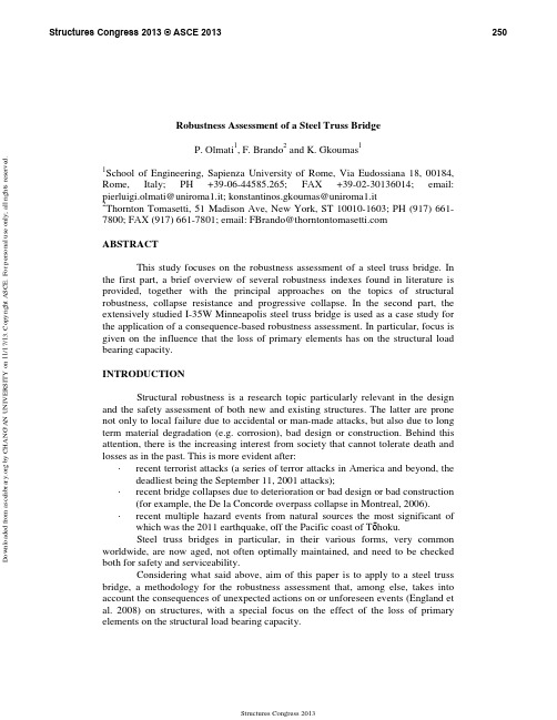
Robustness Assessment of a Steel Truss BridgeP. Olmati 1, F. Brando 2 and K. Gkoumas 11School of Engineering, Sapienza University of Rome, Via Eudossiana 18, 00184, Rome, Italy; PH +39-06-44585.265; FAX +39-02-30136014; email: pierluigi.olmati@uniroma1.it; konstantinos.gkoumas@uniroma1.it 2Thornton Tomasetti, 51 Madison Ave, New York, ST 10010-1603; PH (917) 661-7800; FAX (917) 661-7801; email: FBrando@ABSTRACTThis study focuses on the robustness assessment of a steel truss bridge. Inthe first part, a brief overview of several robustness index es found in literature is provided, together with the principal approaches on the topics of structural robustness, collapse resistance and progressive collapse. In the second part, the extensively studied I-35W Minneapolis steel truss bridge is used as a case study for the application of a consequence-based robustness assessment. In particular, focus is given on the influence that the loss of primary elements has on the structural load bearing capacity.INTRODUCTIONStructural robustness is a research topic particularly relevant in the designand the safety assessment of both new and ex isting structures. The latter are prone not only to local failure due to accidental or man-made attacks, but also due to long term material degradation (e.g. corrosion), bad design or construction. Behind this attention, there is the increasing interest from society that cannot tolerate death and losses as in the past. This is more evident after:· recent terrorist attacks (a series of terror attacks in America and beyond, thedeadliest being the September 11, 2001 attacks);· recent bridge collapses due to deterioration or bad design or bad construction(for example, the De la Concorde overpass collapse in Montreal, 2006).· recent multiple hazard events from natural sources the most significant ofwhich was the 2011 earthquake, off the Pacific coast of T ōhoku.Steel truss bridges in particular, in their various forms, very commonworldwide, are now aged, not often optimally maintained, and need to be checked both for safety and serviceability.Considering what said above, aim of this paper is to apply to a steel trussbridge, a methodology for the robustness assessment that, among else, takes into account the consequences of unexpected actions on or unforeseen events (England et al. 2008) on structures, with a special focus on the effect of the loss of primary elements on the structural load bearing capacity.D o w n l o a d e d f r o m a s c e l i b r a r y .o r g b y C H A N G 'A N U N I VE R S I T Y o n 11/17/13. C o p y r i g h t A S C E .F o r p e r s o n a l u s e o n l y ; a l l r i g h t s r e s e r v e d .STRUCTURAL ROBUSTNESS AND PROGRESSIVE COLLAPSEA variety of terms have been used in literature, however, typicallyrobustness is defined as the “insensitivity of a structure to initial damage” and collapse resistance as the “insensitivity of a structure to abnormal events” (Starossek and Haberland, 2010). Similarly, ASCE 7-05 (2005), defines progressive collapse as the spread of an initial local failure from element to element, eventually resulting in collapse of an entire structure or a disproportionately large part of it. Starossek and Haberland (2010) focus on the differences of progressive and disproportionate collapse, concluding that the terms of disproportionate collapse and progressive collapse are often used interchangeably because disproportionate collapse often occurs in a progressive manner and progressive collapse can be disproportionate.A review of international research on structural robustness anddisproportionate collapse is provided in Arup (2011). Arangio et al. (2011) and Sgambi et al. (2012) provide a dependability framework adapted from the electronic engineering field, where dependability attributes are either related to structural safety or serviceability. Potential failure scenarios specific for bridges are provided in FHWA (2011), within a framework aiming at the resilience improvement. Giuliani (2012) identifies the design strategies for obtaining robustness, using prevention and mitigation measures. An additional aspect is the inherent uncertainty associated with actions and mechanical, geometric and environmental parameters cannot be ignored since they affect the structural response (Petrini and Ciampoli, 2012).Structural robustness assessment meth ods. A relevant issue related to the structural robustness evaluation, is the choice of appropriate synthetic parameters describing for ex ample the sensitivity of a damaged structure in suffering a disproportionate collapse.Eurocode 1 (EN 1991-1-7 2006) merely outlines the issue of structuralrobustness in a qualitative manner, stating that a structure should not be damaged by events to an extent disproportionate to the original cause. Several authors provide a review of methods for assessing structural robustness (Canisius et al. 2007; Starossek and Haberland, 2010; COST, 2011; Sørensen et al. 2012; Parisi and Augenti 2012; Cavaco et al. 2013). In what follows a non-ex haustive overview of approaches for the robustness assessment is provided, focusing on the proposed indexes.Ellingwood and Dusenberry (2005), link the progressive collapse probabilityP(F ) to a chain of probabilities, consisting in (i) the hazard of an abnormal event P(H ), (ii) the local damage as a consequence of this hazard P(D │H ), and (iii) the failure of the structure as a result of the local damage D due to H P(F │DH ).P(F )= P(F │DH )·P(D │H )·P(H )Baker et al. (2008) propose a probabilistic framework for the robustnessassessment, computing both direct risk, associated with the direct consequences of potential damages to the system, and indirect risk, corresponding to the increased risk of a damaged system. The latter corresponds to the robustness of the system, since it can be assumed as a risk from consequences disproportionate to the cause ofD o w n l o a d e d f r o m a s c e l i b r a r y .o r g b y C H A N G 'A N U N I VE R S I T Y o n 11/17/13. C o p y r i g h t A S C E .F o r p e r s o n a l u s e o n l y ; a l l r i g h t s r e s e r v e d .the damage. In their approach, a robust system is considered to be one where indirect risks do not contribute significantly to the total system risk.IndDir DirRob R R R I +=The index takes values from 0 (if all risk is due to indirect consequences) to1 (if there is no risk due to indirect consequences, thus, the system is completely robust).Biondini and Restelli (2008) propose a robustness index (ρ) associated withthe displacements of the system:dos s =ρWhere s 0 is the displacement vector, ║·║ denotes the Euclidian norm, and the subscript “0” and “d” refer respectivelly to the intact and damage state of the structure.Izzuddin et al. (2008) propose a multi-level framework for the progressivecollapse assessment of building structures subject to sudden column loss. The proposed assessment framework utilizes three main stages: (i) nonlinear static response of the damaged structure under gravity loading; (ii) simplified dynamic assessment to establish the maximum dynamic response under sudden column loss; and, (iii) ductility assessment of the connections. Within this framework, they propose that the single measure of structural robustness is the system pseudo-static capacity, that is the maximum value of the nonlinear static resistance for which the resulting maximum dynamic displacement, is less than or equal to the ductility limit. The comparison of the latter against the applied gravity loading establishes the required limit state.Cavaco et al. (2013) consider robustness as the measure of degree ofstructural performance lost after damage occurrence, and propose the following metric (R d : Robustness Index).∫===1)(d d d dxx f RWhere R d indicates the area above the curve defined by the normalized structural performance f (given by the ratio between the structural performance on the intact and damage states), subjected to a normalized damage d (given by the ratio between actual and maximum possible damage).Nafday (2011) discusses the usefulness of consequence event design, forex tremely rare, unforeseen, and difficult to characterize statistically events (black swans). In this view, the author, with reference to truss structures, proposes anD o w n l o a d e d f r o m a s c e l i b r a r y .o r g b y C H A N G 'A N U N I VE R S I T Y o n 11/17/13. C o p y r i g h t A S C E .F o r p e r s o n a l u s e o n l y ; a l l r i g h t s r e s e r v e d .additional design phase that focuses on the robustness, the damage tolerance and the redundancy of the structure. This proposed metric consequence factor C f i for the i-th member is based on the evaluation of the determinants of the normalized stiffness matrixes for the undamaged and damaged structure and is defined as:N i Ni f K K C =Where |K N | is volume of the geometrical shape which is spanned by the vectors of matrix K N for ‘intact condition’ and |K N i | is similar volume under ‘damaged condition’ i.e., after the removal of the i-th member.The robustness, ultimate strength and progressive collapse susceptibility ofsteel truss structures and bridges has been the subject of recent research. Xu and Ellingwood (2011) apply a method of energy-based nonlinear static pushdown analysis on steel frames. Gerasimidis et al. (2012) apply a methodology loosely based on the alternate load path method and obtain robustness measure for geometric irregular steel frames that have the advantage of being comparable. Choi and Chang (2009), focus on the vertical load bearing capacity of truss structures, using a sensitivity index that accounts for the influence of a lost element to the load bearing capacity. Miyachi et al. (2012) focus on how the live load intensity and distribution affect the ultimate strength and ductility of different steel truss bridges, similar to the one considered in this study. Malla et al. (2011) conduct nonlinear dynamic analysis for the progressive failure assessment of bridge truss members, considering their inelastic post-buckling cyclic behavior. Saydam and Frangopol (2011) use FE skills to investigate the vulnerability, redundancy and robustness of truss bridges, taking into account the stochastic time-dependent deterioration of the structure.What emerges from the above is the difference in the approaches andindexes in literature towards the structural robustness quantification. An overview is provided in Table 1.Table 1. Overview of robustness approaches. Robustness Approach Index- property of the structure or property of the structure andthe environment- static or dynamic- linear or non-linear - deterministic or probabilisticMember consequence factor and robustness assessment. Focusing on skeletal structures (e.g. trusses), current member-based design in structural codes does not explicitly consider system safety performance during the structural design, while the level of safety in new designs is usually provided on the basis of intuition and past experience (Nafday, 2008). On the other hand, the Ultimate Limit State (ULS) of the Performance-Based Design (PBD) requires that individual structural members are designed to have a resistance (R) greater than the load action (E), where both R and E are probabilistically characterized (Stewart and Melchers, 1997).D o w n l o a d e d f r o m a s c e l i b r a r y .o r g b y C H A N G 'A N U N I VE R S I T Y o n 11/17/13. C o p y r i g h t A S C E .F o r p e r s o n a l u s e o n l y ; a l l r i g h t s r e s e r v e d .The member-based design is summarized in the following design expression,valid for a single structural member:0E R undamaged d undamaged d ≥−(1)where R d undamaged and E d undamaged are the design values respectively of the resistance and of the solicitation (EN 1990 2002) in the undamaged configuration of the structure. Concerning the commonly implemented standards this equation is not respected with a probability of 10-(6÷7). The method applied here aims to introduce an additional multiplicative coefficient in the first term of the Eq. (1): this is identified as the member consequence factor (C f ), takes values within a range from 0 to 1, and quantifies the influence that a loss of a structural element has on the load carrying capacity. Essentially, if C f tends to 1, the member is likely to be important to the structural system; instead if C f tends to 0, the member is likely to be unimportant to the structural system. C f provides to the single structural member an additional load carrying capacity, in function of the nominal design (not ex treme) loads. This additional capacity can be used for contrasting unexpected and extreme loads.0E R *)C 1(undamagedd undamaged d scenario f≥−− (2)Nafday (2011) provides Eq. (2) in a similar manner, with the only differencebeing on the range mean of C f that is the inverse of the proposed one, so the first term of Eq. (2) is multiplied directly by C f . Thus, in this study the equation proposed by (Nafday 2011) has been slightly revised in order to fit with the here proposed expression of the C f - see both Eq. (2) and Eq. (3). The structure is subjected to a set of damage scenarios and the consequence of the damages is evaluated by the consequence factor (C f scenario ) that for convenience can be easily ex pressed in percentage. For damage scenario is intended the failure of one or more structural elements.Considering the above, robustness can be ex pressed as the complement to100 of C f scenario , intended as the effective coefficient that affects directly the resistance - see Eq. (2). C f scenario is evaluated by the maximum percentage difference of the structural stiffness matrix eigenvalues of the damaged and undamaged configurations of the structure.N 1i un idami un i scenario f100)(max C−=⎟⎟⎠⎞⎜⎜⎝⎛λλ−λ= (3)where, λi un and λi dam are respectively the i-th eigenvalue of the structural stiffness matrix in the undamaged and damaged configuration, and N is the total number of the eigenvalues.The corresponding robustness index (R scenario ) related to the damage scenariois therefore defined as:D o w n l o a d e d f r o m a s c e l i b r a r y .o r g b y C H A N G 'A N U N I VE R S I T Y o n 11/17/13. C o p y r i g h t A S C E .F o r p e r s o n a l u s e o n l y ; a l l r i g h t s r e s e r v e d .scenario fscenario C 100R −= (4)Values of C f close to 100% mean that the failure of the structural membermost likely causes a global structural collapse. Low values of C f do not necessarily mean that the structure survives after the failure of the structural member: this is something that must be established by a non-linear dynamic analysis that considers the loss of the specific structural member. A value of C f close to 0% means that the structure has a good structural robustness.Some further considerations are necessary. The proposed method forcomputing the consequence factors should not be used 1) for structures that have high concentrated masses (especially non-structural masses) in a particular zone, and 2) for structures that have cable structural system (e.g. tensile structures, suspension bridges).The first issue is related to the dynamic nature of a structural collapse, sinceEq. (3) does not take into account the mass matrix of the system that is directly related to the inertial forces. It is possible to accept this limitation only if the masses are those of the structural members, thus distributed uniformly. Moreover there is no way to consider any dynamic magnification phenomena with Eq. (3).The second issue is related to the geometrical non-linearity of cablestructures. For such structures the stiffness matrix is a function of the loads, something not accounted for in the elastic stiffness matrix. Moreover for the nature of the elastic stiffness matrix, eventual structural dissipative behaviors and non-linear resistive mechanisms (e.g. catenary action) are not taken into account.In the authors’ opinion the above limitations can be accepted if the desiredoutcome is a non-computational ex pensive method, since the C f value provides an indication of the structural robustness in a quick and smart manner. Thus, the C f as ex pressed in Eq. (3) can be used primarily as an index to establish the critical structural members for the global structural stability, or to compare different structural design solutions from a robustness point of view. The latter implementation of C f can be helpful for the robustness assessment of complex structures, such as wind turbine jacket structures (Petrini et al. 2010), since it provides an indication on the key structural elements that in a complex structure are of difficult evaluation.The method applied in this study aims at increasing the collapse resistance ofa structure, by focusing on the resistance of the single structural members, and accounting for their importance to the global structural behavior consequently to a generic ex treme event that can cause a local damage. Moreover, the method is particularly helpful for unpredictable events that by definition are not possible to take into account in the design phase. This does not mean that the collapse resistance is accounted only for the single member resistance, because the authors intend, as a design philosophy, to increase the resistance of the single members in addition to the structural stability analysis that provide the assessment of the global structural behavior.Thus, this method neglects the “load characterization” of the ex treme loadsince it is considered unpredictable, and it is complementary to the so-called threat independent stability analyses (DoD, 2009).D o w n l o a d e d f r o m a s c e l i b r a r y .o r g b y C H A N G 'A N U N I VE R S I T Y o n 11/17/13. C o p y r i g h t A S C E .F o r p e r s o n a l u s e o n l y ; a l l r i g h t s r e s e r v e d .APPLICATION ON A STEEL TRUSS BRIDGEThis section focuses on the robustness assessment of a steel truss bridgeusing the member consequence factor method. The bridge used as a case study is the I-35 West Bridge in Minneapolis. The I-35 West Bridge was built in the early 1960s and opened to traffic in 1967. The bridge spanned across the Mississippi River, Minneapolis and it was supported on thirteen reinforced concrete piers and consisted of fourteen spans. Eleven of the fourteen spans were approach spans to the main deck truss portion. The total length of the bridge including the approach and deck truss was approximately 580 meter (1,907 feet). The length of the continuous deck truss portion which spanned over four piers was approx imately 324 meter (1,064 feet). The elevation of the deck truss portion of the bridge is shown in Figure 1.Figure 1. Bridge overview (edited from MnDOT).The deck truss portion of the bridge was supported on a pinned bearing atPier 7 and roller bearings at the other three supports. The main bridge trusses were comprised of built-up welded box and I-sections sandwiched by gusset plates at each panel point. The collapse which occurred on August 1st 2007 was probably due to a combination of the temperature effect, roller bearings condition, and increased gravity loads on the bridge prior to collapse. For this functionally non-redundant bridge the initial buckle at the lower chord member close to the pier and local plastic hinges in the member resulted in global instability and collapse (Malsch et al. 2011).The bridge has been thoroughly studied by Brando et al. (2010) focusing onthe issues of redundancy, progressive collapse and robustness. Studies have been conducted in order to assess the effect of the collapse of specific structural components (Crosti and Duthinh, 2012), while Crosti et al. (2012) performed non-linear dynamic analysis on specific damage scenarios.For computing the consequence factors and the robustness index of thestructure for the selected damage scenarios a FE model of the structure is necessary. Figure 2 shows the three-dimensional FE model of the I-35 West Bridge built using the commercial FE solver Sap2000® (Brando et al. 2010).Both shell and beam finite elements are used in the FE model. The bridgesuperstructure and both the deck girders and beams are built using beam elements, while, the concrete deck is modeled using shell elements. Moreover, contact links connect the deck with both the deck girders and beams. In accordance to the original blueprints of the I-35 West Bridge (MnDOT 2012), standard and non-conventional beam cross sections are implemented in the model.3 Span Continuous Trusses – 1,064 ftPier 7Pier 6NorthPier 8 Pier 5D o w n l o a d e d f r o m a s c e l i b r a r y .o r g b y C H A N G 'A N U N I VE R S I T Y o n 11/17/13. C o p y r i g h t A S C E .F o r p e r s o n a l u s e o n l y ; a l l r i g h t s r e s e r v e d .Figure 2. 3D FE model of the I-35 West Bridge.From this model a simplified (plane) FE model is extracted and is adoptedfor computing the structural stiffness matrix in both the damaged and undamaged configurations. This choice has mostly to do with computational challenges in computing the stiffness matrix for the full model. Regarding the structural decomposition of complex structures it is possible to refer to the Bontempi et al. (2008) and Petrini and Bontempi (2011).The ex pression of the consequence factor provided by Eq. 4 refers to theeigenvalues of the elastic stiffness matrix. The choice to use a simplified model is also justified and feasible since Eq. 4 is independent from the mass of the structure. Eq. 4 is also independent from the loads, so the loads in the FE model are not considered. The concrete deck is only simply-supported by the bridge superstructure, so the concrete deck is not considered in the analyses and it is omitted in the model, consequently, the contact links are deleted as well. The deck girders and beams are also omitted since they do not have a strong influence to the load bearing capacity of the bridge. The two trusses of the bridge superstructure are similar and connected by a transverse truss structure, so the analyses focus on a single truss; at this point one plane truss is obtained from the three-dimensional model, in order to have a two-dimensional FE model, implemented for computing the stiffness matrix in both the damaged and undamaged configurations.Concluding, only a single lateral truss of the bridge is considered, and a setof damage scenario is selected (Figure 3).Figure 3. Lateral truss of the bridge and selection of damage scenarios.The damage scenarios for this application are not cumulative, so only asingle member is removed from the model for each damage scenario. In this6721345D o w n l o a d e d f r o m a s c e l i b r a r y .o r g b y C H A N G 'A N U N I VE R S I T Y o n 11/17/13. C o p y r i g h t A S C E .F o r p e r s o n a l u s e o n l y ; a l l r i g h t s r e s e r v e d .application the scenarios chosen focus on the area recognized as initiating the collapse according to forensic investigations (Brando et al. 2013).With the aim of increasing the structural robustness of the bridge, and inorder to test the sensitivity of the method proposed, an improved variation of the structural system is considered. In this case (Figure 4) the updated bridge truss is a hyper-static steel truss structure.The results of both the original and the enhanced structural schemes, underthe same damage scenarios, are shown in Figure 5.Figure 4. Updated lateral truss of the bridge and selection of damage scenarios.The proposed robustness index (based on the member consequence factor C f )captures both the lack of robustness of the I-35 W Bridge, and its robustness enhancement as a consequence of increasing the redundancy of the structure.Figure 5. Damage scenario evaluation.Generally speaking, it can be observed that the case-study bridge shows alow robustness index . This is due to the fact that it is (internally) statically determined. From the analysis of the bridge in its original configuration and for the chosen damages configurations, a consequence factor of 0.77 has been computed for67213453759424535382363415855656277204060801001234567R o b u s t n e s s %Damage ScenarioCf maxRobustness8387885360866417131247401436204060801001234567R o b u s t n e s s %Damage ScenarioCf maxRobustnessD o w n l o a d e d f r o m a s c e l i b r a r y .o r g b y C H A N G 'A N U N I VE R S I T Y o n 11/17/13. C o p y r i g h t A S C E .F o r p e r s o n a l u s e o n l y ; a l l r i g h t s r e s e r v e d .the DS7 and, consequently, a robustness index of 0.23 is obtained.The consequence factors obtained by the analysis of the various damagescenarios can be used, as shown in Eq. (2), for the re-sizing of the structural elements In this case the structural scheme of the bridge does not change with respect to the original one and this option can be considered as a local (element-based) improvement of the structural system. In alternative, the consequence factor can be used only as a robustness performance index, without making use of Eq. (2). More than one structural configuration can be examined in order to assess which is the best solution in terms of C f . An ex ample of this strategy is given in the application of Figure 4. In the examined case the consequence factor obtained by the DS7 decreases from 0.77 to 0.36; this appreciable result is probably due to the position of the failed element in the DS7, which, being a lower element of the truss plays an important role in the load carrying capacity of the original system. Generally speaking, the redundant bridge configuration (Figure 4) shows certain insensitivity to the internal damage scenarios (number 1, 2 and 3). This option can be considered as a global improvement of the structural system. The previous strategies can be adopted simultaneously: i) the designer-sizing of the elements can be affected by the robustness index by using Eq. (2); and ii) the structural scheme can be changed (also on the basis of the C f values) in order to increase the robustness. In this case, both local and global solutions provide improvements to the structural system.CONCLUSIONSome brief considerations can be made on the findings for the specificapplication. The proposed metric seems to be promising for the robustness assessment of a complex structural system, and could be used as tool for localizing critical areas in the design, analysis and investigation phases. Furthermore, comprehensive assessments that consider a larger set of damage scenarios can be performed by implementing this method using appropriate search heuristics. Limitations of the implemented method arise from the fact that in the analyses a reduced structural system is used. In this sense, findings can be considered as merely preliminary, and have to be verified using complete models and advanced numerical analyses. Finally, an improved expression of the C f could be obtained by considering both the stiffness and mass matrix of the structure and the plasticity of the elements.REFERENCESfor dependability". Struct. Infrastruct. E., 7(1), 75-86.Arup (2011) Review of international research on structural robustness anddisproportionate collapse , London: Department for Communities and Local Government.ASCE 7-05 (2005) Minimum design loads for buildings and other structures ,American Society of Civil Engineers (ASCE).robustness”. Struct. Saf . 30(3),253–267.D o w n l o a d e d f r o m a s c e l i b r a r y .o r g b y C H A N G 'A N U N I VE R S I T Y o n 11/17/13. C o p y r i g h t A S C E .F o r p e r s o n a l u s e o n l y ; a l l r i g h t s r e s e r v e d .。
USP 1223 VALIDATION OF ALTERNATIVE MICROBIOLOGICAL METHODS
1223VALIDATION OF ALTERNATIVE MICROBIOLOGICAL METHODSINTRODUCTIONThe purpose of this chapter is to provide guidance for validating methods for use as alternatives to the official compendial microbiological methods. For microbial recovery and identification, microbiological testing laboratories sometimes use alternative test methods to those described in the general chapters for a variety of reasons, such as economics, throughput, and convenience. Validation of these methods is required. Some guidance on validation of the use of alternate methods is provided in the Tests and Assays section in the General Notices and Requirements. This section also notes that in the event of a dispute, only the result obtained by the compendial test is conclusive.Validation studies of alternate microbiological methods should take a large degree of variability into account. When conducting microbiological testing by conventional plate count, for example, one frequently encounters a range of results that is broader (%RSD 15 to 35) than ranges in commonly used chemical assays (%RSD 1 to 3). Many conventional microbiological methods are subject to sampling error, dilution error, plating error, incubation error, and operator error.Validation of Compendial Procedures 1225defines characteristics such as accuracy, precision, specificity, detection limit, quantification limit, linearity, range, ruggedness, and robustness in their application to analytical methods. These definitions are less appropriate for alternate microbiological m ethod validation as ―at least equivalent to the compendial method‖ given the comparative nature of the question (see the Tests and Assays—Procedures section in General Notices and Requirements). The critical question is whether or not the alternate method will yield results equivalent to, or better than, the results generated by the conventional method.Other industry organizations have provided guidance for the validation of alternate microbiological methods.* The suitability of a new or modified method should be demonstrated in a comparison study between the USP compendial method and the alternate method. The characteristics defined in this chapter may be used to establish this comparison.TYPES OF MICROBIOLOGICAL TESTSIt is critical to the validation effort to identify the portion of the test addressed by an alternate technology. For example, there is a variety of technologies available to detect the presence of viable cells. These techniques may have application in a variety of tests (e.g., bioburden, sterility test) but may not, in fact, replace the critical aspects of the test entirely. For example, a sterility test by membrane filtration may be performed according to the compendial procedure up to the point of combining the processed filter with therecovery media, and after that the presence of viable cells might then be demonstrated by use of some of the available technologies. Validation of this application would, therefore, require validation of the recovery system employed rather than the entire test.There are three major types of determinations specific to microbiological tests. These include tests to determine whether microorganisms are present in a sample, tests to quantify the number of microorganisms (or to enumerate a specific subpopulation of the sample), and tests designed to identify microorganisms. This chapter does not address microbial identification.Qualitative Tests for the Presence or Absence of MicroorganismsThis type of test is characterized by the use of turbidity in a liquid growth medium as evidence of the presence of viable microorganisms in the test sample. The most common example of this test is the sterility test. Other examples of this type of testing are those tests designed to evaluate the presence or absence of a particular type of microorganism in a sample (e.g., coliforms in potable water and E. coli in oral dosage forms).Quantitative Tests for MicroorganismsThe plate count method is the most common example of this class of tests used to estimate the number of viable microorganisms present in a sample. The membrane filtration and Most Probable Number (MPN) multiple-tube methods are other examples of these tests. The latter was developed as a means to estimate the number of viable microorganisms present in a sample not amenable to direct plating or membrane filtration.General ConcernsValidation of a microbiological method is the process by which it is experimentally established that the performance characteristics of the method meet the requirements for the intended application, in comparison to the traditional method. For example, it may not be necessary to fully validate the equivalence of a new quantitative method for use in the antimicrobial efficacy test by comparative studies, as the critical comparison is between the new method of enumeration and the plate count method (the current method for enumeration). As quantitative tests, by their nature, yield numerical data, they allow for the use of parametric statistical techniques. In contrast, qualitative microbial assays, e.g., the sterility test in the example above, may require analysis by nonparametric statistical methods. The validation of analytical methods for chemical assays followswell-established parameters as described in Validation of Compendial Procedures 1225. Validation of microbiological methods shares some of the same concerns, although consideration must be given to the unique nature of microbiological assays (see Table 1).Table 1. Validation Parameters by Type of Microbiological TestVALIDATION OF QUALITATIVE TESTS FOR DEMONSTRATION OF VIABLEMICROORGANISMS IN A SAMPLESpecificityThe specificity of an alternate qualitative microbiological method is its ability to detect a range of microorganisms that may be present in the test article. This concern is adequately addressed by growth promotion of the media for qualitative methods that rely upon growth to demonstrate presence or absence of microorganisms. However, for those methods that do not require growth as an indicator of microbial presence, the specificity of the assay for microbes assures that extraneous matter in the test system does not interfere with the test.Limit of DetectionThe limit of detection is the lowest number of microorganisms in a sample that can be detected under the stated experimental conditions. A microbiological limit test determines the presence or absence of microorganisms, e.g., absence of Salmonella spp. in 10 g. Due to the nature of microbiology, the limit of detection refers to the number of organisms present in the original sample before any dilution or incubation steps; it does not refer to the number of organisms present at the point of assay.One method to demonstrate the limit of detection for a quantitative assay would be to evaluate the two methods (alternative and compendial) by inoculation with a low number of challenge microorganisms (not more than 5 cfu per unit) followed by a measurement of recovery. The level of inoculation should be adjusted until at least 50% of the samples show growth in the compendial test. It is necessary to repeat this determination several times, as the limit of detection of an assay is determined from a number of replicates (notless than 5). The ability of the two methods to detect the presence of low numbers of microorganisms can be demonstrated using the Chi square test. A second method to demonstrate equivalence between the two quantitative methods could be through the use of the Most Probable Number technique. In this method, a 5-tube design in a ten-fold dilution series could be used for both methods. These would then be challenged with equivalent inoculums (for example, a 10–1, 10–2, and 10–3 dilution from a stock suspension of approximately 50 cfu per mL to yield target inocula of 5, 0.5, and 0.05 cfu per tube) and the MPN of the original stock determined by each method. If the 95% confidence intervals overlapped, then the methods would be considered equivalent.RuggednessThe ruggedness of a qualitative microbiological method is the degree of precision of test results obtained by analysis of the same samples under a variety of normal test conditions, such as different analysts, instruments, reagent lots, and laboratories. Ruggedness can be defined as the intrinsic resistance to the influences exerted by operational and environmental variables on the results of the microbiological method. Ruggedness is a validation parameter best suited to determination by the supplier of the test method who has easy access to multiple instruments and batches of components.RobustnessThe robustness of a qualitative microbiological method is a measure of its capacity to remain unaffected by small but deliberate variations in method parameters, and provides an indication of its reliability during normal usage. Robustness is a validation parameter best suited to determination by the supplier of the test method. As there are no agreed upon standards for current methods, acceptance criteria are problematic and must be tailored to the specific technique. It is essential, however, that an estimate of the ruggedness of the alternate procedure be developed. The measure of robustness is not necessarily a comparison between the alternate method and the traditional, but rather a necessary component of validation of the alternate method so that the user knows the operating parameters of the method.VALIDATION OF QUANTITATIVE ESTIMATION OF VIABLE MICROORGANISMS IN ASAMPLEAs colony-forming units follow a Poisson distribution, the use of statistical tools appropriate to the Poisson rather than those used to analyze normal distributions is encouraged. If the user is more comfortable using tools geared towards normally distributed data, the use of a data transformation is frequently useful. Two techniques are available and convenient for microbiological data. Raw counts can be transformed to normally distributed data either by taking the log10 unit value for that count, or by takingthe square root of count +1. The latter transformation is especially helpful if the data contain zero counts.AccuracyThe accuracy of this type of microbiological method is the closeness of the test results obtained by the alternate test method to the value obtained by the traditional method. It should be demonstrated across the operational range of the test. Accuracy is usually expressed as the percentage of recovery of microorganisms by the assay method. Accuracy in a quantitative microbiological test may be shown by preparing a suspension of microorganisms at the upper end of the range of the test, that has been serially diluted down to the lower end of the range of the test. The operational range of the alternate method should overlap that of the traditional method. For example, if the alternate method is meant to replace the traditional plate count method for viable counts, then a reasonable range might be from 100 to 106 cfu per mL. At least 5 suspensions across the range of the test should be analyzed for each challenge organism. The alternate method should provide an estimate of viable microorganisms not less than 70% of the estimate provided by the traditional method, or the new method should be shown to recover at least as many organisms as the traditional method by appropriate statistical analysis, an example being an ANOVA analysis of the log10 unit transforms of the data points. Note that the possibility exists that an alternate method may recover an apparent higher number of microorganisms if it is not dependent on the growth of the microorganisms to form colonies or develop turbidity. This is determined in the Specificity evaluation.PrecisionThe precision of a quantitative microbiological method is the degree of agreement among individual test results when the procedure is applied repeatedly to multiple samplings of suspensions of laboratory microorganisms across the range of the test. The precision of a microbiological method is usually expressed as the standard deviation or relative standard deviation (coefficient of variation). However, other appropriate measures may be applied. One method to demonstrate precision uses a suspension of microorganisms at the upper end of the range of the test that has been serially diluted down to the lower end of the range of the test. At least 5 suspensions across the range of the test should be analyzed. For each suspension at least 10 replicates should be assayed in order to be able to calculate statistically significant estimates of the standard deviation or relative standard deviation (coefficient of variation). Generally, a RSD in the 15% to 35% range would be acceptable. Irrespective of the specific results, the alternate method should have a coefficient of variation that is not larger than that of the traditional method. For example, a plate count method might have the RSD ranges as shown in the following table.Table 2. Expected RSD as a Function of cfu per PlateThe specificity of a quantitative microbiological method is its ability to detect a panel of microorganisms suitable to demonstrate that the method is fit for its intended purpose. This is demonstrated using the organisms appropriate for the purpose of the alternate method. It is important to challenge the alternate technology in a manner that would encourage false positive results (specific to that alternate technology) to demonstrate the suitability of the alternate method in comparison to the traditional method. This is especially important with those alternate methods that do not require growth for microbial enumeration (for example, any that do not require enrichment or can enumerate microorganisms into the range of 1–50 cells).Limit of QuantificationThe limit of quantification is the lowest number of microorganisms that can be accurately counted. As it is not possible to obtain a reliable sample containing a known number of microorganisms, it is essential that the limit of quantification of an assay is determined from a number of replicates (n > 5) at each of at least 5 different points across the operational range of the assay. The limit of quantification should not be a number greater than that of the traditional method. Note that this may have an inherent limit due to the nature of bacterial enumeration and the Poisson distribution of bacterial counts (see Validation of Microbial Recovery from Pharmacopeial Articles 1227). Therefore, the alternate method need only demonstrate that it is at least as sensitive as the traditional method to similar lower limits.LinearityThe linearity of a quantitative microbiological test is its ability to produce results that are proportional to the concentration of microorganisms present in the sample within a given range. The linearity should be determined over the range of the test. A method to determine this would be to select at least 5 concentrations of each standard challenge microorganism and conduct at least 5 replicate readings of each concentration. An appropriate measure would be to calculate the square of the correlation coefficient, r2, from a linear regression analysis of the data generated above. While the correlation coefficient does not provide an estimate of linearity, it is a convenient and commonly applied measure to approximate the relationship. The alternate method should not have an r2 value less than 0.95.Limit of DetectionSee Limit of Detection under Validation of Qualitative Tests for Demonstration of Viable Microorganisms in a Sample.RangeThe operational range of a quantitative microbiological method is the interval between the upper and lower levels of microorganisms that have been demonstrated to be determined with precision, accuracy, and linearity.RuggednessSee Ruggedness under Validation of Qualitative Tests for Demonstration of Viable Microorganisms in a Sample.RobustnessSee Robustness under Validation of Qualitative Tests for Demonstration of Viable Microorganisms in a Sample.* PDA Technical Report No. 33. The Evaluation, Validation and Implementation of New Microbiological Testing Methods. PDA Journal of Pharmaceutical Science & Technology.54 Supplement TR#33 (3) 2000 and Official Methods Programs of AOAC International.。
Robustness of Adiabatic Quantum Computing
a r X i v :0805.2757v 1 [q u a n t -p h ] 18 M a y 2008Robustness of Adiabatic Quantum Computing Seth Lloyd,MIT Abstract:Adiabatic quantum computation for performing quantum computations such as Shor’s algorithm is protected against thermal errors by an energy gap of size O (1/n ),where n is the length of the computation to be performed.Adiabatic quantum computing is a novel form of quantum information processing that allows one to find solutions to NP-hard problems with at least a square root speed-up [1].In some cases,adiabatic quantum computing may afford an exponential speed-up over classical computation.It is known that adiabatic quantum computing is no stronger than conventional quantum computing,since a quantum computer can be used to simulate an adiabatic quantum computer.Aharonov et al.showed that adiabatic quantum computing is no weaker than conventional quantum computation [2].This paper presents novel modelsfor adiabatic quantum computation and shows that adiabatic quantum computation is intrinsically protected against thermal noise from the environment.Indeed,thermal noise can actually be used to ‘help’an adiabatic quantum computation along.A simple way to do adiabatic versions of ‘conventional’quantum computing is to use the Feynman pointer consisting of a line of qubits [3].The Feynman Hamiltonian isH =−n −1ℓ=0U ℓ⊗|ℓ+1 ℓ|+U †ℓ⊗|ℓ ℓ+1|,(1)where U ℓis the unitary operator for the ℓ’th gate and |ℓ is a state of the pointer where the ℓ’th qubit is 1and all the remaining qubits are 0.Clearly,H is local and each of itsterms acts on four qubits at once for two-qubit gates.If we consider the pointer to be a ‘unary’variable,then the each of the terms of H acts on two qubits and the unary pointer variable.Assume that the computation has been set up so that all qubits start in the state 0.The computation takes place and the answer is placed in an answer register.Now a long set of steps,say n/2takes place in which nothing happens.Then the computation is undone,returning the system to its initial state at the n−1’th step.The computational circuit then wraps around and begins again.The eigenstates of H then have the form|b,k =(1/√Now gradually turn on an H term while turning offthe H1term:the total Hamiltonian isηH0+(1−λ)H1+λH.Asλis turned on,the system goes to its new ground state |b=0,k=0 .It can be verified numerically and analytically[7]that the minimum energygap in this system occurs atλ=1:consequently,the minimum gap goes as1/n2.In fact, the energy gap due to the interaction between the H1and the H terms is just the energy gap of the simpler system consisting just of the chain qubits on their own,confined to the subspace in which exactly one qubit is1:that is,it is the energy gap of a qubit chain with Hamiltonian(1−λ)H1+λH′,where H′=− ℓ|ℓ+1 ℓ|+|ℓ ℓ+1|.This gap goes as1/n2.Accordingly,the amount of time required to perform the adiabatic passage is polynomial in n.When the adiabatic passage is complete,the energy gap of the H term on its own goes as1/n2from the cosine dependence of the eigenvalues of H:it is also just the energy gap of the simplified system in the previous paragraph.This implies that the adiabatic passage can accurately be performed in a time polynomial in n.Measuring the answer register now gives the answer to the computation with probability1/2.This is an alternative(and considerably simpler)demonstration to that of[2]that‘conventional’quantum computation can be performed efficiently in an adiabatic setting.An interesting feature of this procedure is that the adiabatic passage can be faulty and still work justfine:all of the energy eigenstates in the|b=0,k sector give the correct answer to the computation with probability1/2,for any k.The real issue is making sure we do not transition to the|b=0,k sector.But the Hamiltonians H1and H do not couple to this sector:so in fact,we can perform the passage non-adiabatically and still get the answer to the computation.For example,if we turn offthe H1Hamiltonian very rapidly and turn on the H Hamiltonian at the same time,the system is now in an equal superposition of all the|b=0,k eigenstates.If we wait for a time∝n2(corresponding to the inverse of the minimum separation between the eigenvalues of H),then the state of the system will be spread throughout the|b=0,k sector,and we can read out the answer with probability1/2.This method effectively relies on dispersion of the wavepacket tofind the answer.Since coherence of the pointer doesn’t matter,we can also apply a Hamiltonian to the pointer that tilts the energy landscape so that higher pointer values have lower energy.(E.g.,H pointer=− ℓℓE|ℓ ℓ|.)Starting the pointer offin the initial state above and letting it interact with a thermal environment will obtain the answer to the computationin time of O(n).Similarly,in the absence of an environment,starting the pointer offin a wavepacket with zero momentum at time0and letting it accelerate will get the answer to the computation in even shorter time.Clearly,this method is quite a robust way of performing quantum computation.Let us look more closely at the sources of this robustness.Ifηis big,then there is a separation of energy of O(η/n)between the|b=0,k sector—states which give the correct answer to the computation—and the|b=0,k sector—states which give the incorrect answer to the computation.This is because b=0,k|ηH0|b=0,k =η/n.This energy gap goesdown only linearly in the length of the computation and can be made much larger than the gap between the ground andfirst excited state by increasingη>>1.This second energy gap is very useful:it means that thermal excitations with an energy below the gap will not interfere with obtaining the proper answer.That is,this method is intrinsically error-tolerant in the face of thermal noise.Indeed,it is this O(η/n) gap that determines how rapidly the computation can take place rather than the O(1/n2) gap between the ground and excited states.Of course,the actual errors in a system that realizes the above scheme are likely to arise from variability in the applied Hamiltonians.The energy gap arguments for robustness only apply to the translational dynamics of the system(this is what makes the analysis of the system tractable in thefirst place).That is,errors that affect each Uℓon its own are not protected against:but these are the errors that cause the computation to come out wrong.Of course,one can always program the circuit to perform‘conventional’robust quantum computation to protect against such errors.One must be careful,however,that errors that entangle the pointer with the logical qubits do not contaminate other qubits: conventional robust quantum computation protocols will have to be modified to address this issue.Farhi et al.have recently exhibited error correcting codes for‘conventional’adiabatic quantum computation[1]that can protect against such computational errors[8].The use of error correcting codes to correct the variation in the Uℓmay well be overkill. In any system manufactured to implement adiabatic quantum computing,these errors in the Uℓare essentially deterministic:the Uℓcould in principle be measured and their varia-tion from their nominal values compensated for by tuning the local Hamiltonians.Because it involves no added redundancy,such an approach is potentially more efficient than the use of quantum error correcting codes.Exactly how to detect and correct variations in the Uℓwill depend on the techniques(e.g.,quantum dots or superconducting systems)used toconstruct adiabatic quantum circuits.It is also interesting to note that performing quantum computation adiabatically is intrinsically more energy efficient than performing a sequence of quantum logic gates via the application of a series of external pulses.The external pulses must be accurately clocked and shaped,which requires large amounts of energy.In the schemes investigated here,the internal dynamics of the computer insure that quantum logic operations are performed in the proper order,so no clocking or external pulses need be applied.The adiabatic technique also avoids the Anderson localization problem raised by Landauer.The above construction requires an external pointer and four qubit interactions.One can also set up a pointerless model that requires only pairwise interactions between spin1/2 particles(compare the following method with the method proposed in reference[9]).Let each qubit in the computational circuit correspond to a particle with two internal states. Let each wire in the circuit correspond to a mode that can be occupied by a particle.The ℓ’th quantum logic gate then corresponds to an operator˜Hℓ=Aℓ+A†,where Aℓis anℓoperator that takes two particles from the two input modes and moves them to the output modes while performing a quantum logic operation on their two qubits.That is,Aℓ=a†out1a in1a†out2a in2⊗Uℓ.(5) Note that Aℓacts only when both input modes are occupied by a qubit-carrying particle. If we use the Hamiltonian˜H= ℓ˜Hℓin place of H in the construction above,the ground state of this Hamiltonian is a superposition of states in which the computation is at various stages of completion.Just as above,measurement on the ground state will reveal the answer to the computation with probability1/2.Note that even though the Hamiltonian in equation(5)involves a product of opera-tors on four degrees of freedom(the internal degrees of freedom of the particles together with their positions),it is nonetheless a physically reasonable local Hamiltonian involv-ing pairwise interactions between spin-1/2particles.To simulate its operation using an array of qubits as in[2]would require four qubit interactions,as in the pointer model dis-cussed above.This point is raised here because of the emphasis in the quantum computing literature on reducing computation to pairwise interactions between qubits.Pairwise in-teractions between particles orfields–i.e.,the sort of interactions found in nature–may correspond to interactions between more than two qubits.Without further restrictions on the form of the quantum logic circuit,evaluating the energy gap in this particle model is difficult,even for thefinal Hamiltonian1−˜H.But wecan always set up the computational circuit in a way that allows the adiabatic passage to be mapped directly on the Feynman pointer model above.The method is straightforward: order the quantum logic gates as above.Now insert additional quantum logic gates between each consecutive pair of gates in the original circuit.The additional gate inserted between theℓ’th andℓ+1’th quantum logic gates couples one output qubit of theℓ’th quantum logic gate with one input qubit of theℓ+1’th gate,and performs a trivial operation U=1on the internal qubits of these gates.The purpose of these gates is ensure that the quantum logic operations are performed in the proper sequence.Effectively,one of the qubits from theℓ’th gate must‘tag’one of the qubits from theℓ+1’th gate before theℓ+1’th gate can be implemented.Accordingly,we call this trick,a‘tag-team’quantum circuit.Tag-team quantum circuits are unitarily equivalent to the Feynman pointer model with an extra,identity gate inserted between each of the original quantum logic gates. Accordingly,the spectral gap for tag-team quantum circuits goes as1/n2and the quantum computation can be performed in time O(poly(n)).Just as for the pointer version of adiabatic quantum computing,the important spectral gap for tag-team adiabatic quantum computation is not the minimum gap,but rather the gap of size O(η/n)between the ground-state manifold of‘correct’states and the next higher manifold of‘incorrect’states. Once again,the existence of this gap is a powerful protection against errors in adiabatic quantum computation.The methods described above represent an alternative derivation of the fact that adiabatic quantum information processing can efficiently perform conventional quantum computation.The relative simplicity of the derivation from the original Feymnan Hamil-tonian[3]allows an analysis of the robustness of the scheme against thermal excitations. Adiabatic implementations of quantum computation are robust against thermal noise at temperatures below the appropriate energy gap.The appropriate energy gap is not the minimum gap,which scales as n2,but the gap between the lowest sector of eigenstates, which give the correct answer,and the next sector.This gap scales asη/n,whereηis an energy parameter that is within the control of the experimentalist.Acknowledgements:This work was supported by ARDA,ARO,DARPA,CMI,and the W.M.Keck foundation.The author would like to thank D.Gottesman and D.Nagaj for helpful conversations.References:[1]E.Farhi,J.Goldstone,S.Gutmann,Science292,472(2001).[2]D.Aharonov,W.van Dam,J.Kempe,ndau,S.Lloyd,O.Regev,‘Adiabatic Quantum Computation is Equivalent to Standard Quantum Computation,’Proceedings of the45th Annual IEEE Symposium on Foundations of Computer Science(FOCS’04), 42-51(2004);quant-ph/0405098.[3]R.Feynman,Found Phys.16,507-531(1986).[4]E.Farhi,S.Gutmann,Phys.Rev.A58,915-928(1998).[5]D.Aharonov,A.Ambainis,J.Kempe,U.Vazirani,Proceeding of the thirty-third annual ACM symposium on Theory of Computing,pp.50-59(2001).[6]ndauer,Phil.Trans.:Phys.Sci.and Eng.,353,367-376(1995).[7]P.Deift,M.B.Ruskai,W.Spitzer,arXiv:quant-ph/0605156.[8]S.P.Jordan,E.Farhi,P.Shor,Phys Rev A74,052322(2006);quant-ph/0512170.[9]A.Mizel,D.A.Lidar,M.Mitchell,Phys.Rev.Lett.99,070502(2007)arXiv:quant-ph/0609067.。
- 1、下载文档前请自行甄别文档内容的完整性,平台不提供额外的编辑、内容补充、找答案等附加服务。
- 2、"仅部分预览"的文档,不可在线预览部分如存在完整性等问题,可反馈申请退款(可完整预览的文档不适用该条件!)。
- 3、如文档侵犯您的权益,请联系客服反馈,我们会尽快为您处理(人工客服工作时间:9:00-18:30)。
Robustness Testing of A Distributed Simulation BackplaneMasters ThesisKimberly FernslerAdvisor: Philip KoopmanDepartment of Electrical & Computer EngineeringCarnegie Mellon UniversityPittsburgh, Pennsylvania 15213kf@May 3, 1999Robustness Testing of A Distributed Simulation Backplane AbstractCreating robust software requires quantitative measurement in addition to careful specification and implementation. The Ballista software robustness testing service provides exception handling measure-ments for a variety of application domains. This thesis describes Ballista testing of the High Level Archi-tecture Run-Time Infrastructure (HLA RTI), a general-purpose distributed simulation backplane developed by the Defense Modeling and Simulation Office that has been specifically designed for robust exception handling. While more robust than off-the-shelf POSIX operating systems, the RTI had normal-ized robustness failure rates as high as 10.2%. Non-robust testing responses included exception handling errors, hardware segmentation violations, “unknown” exceptions, and task hangs. Additionally, testing repeatedly crashed one version of the RTI client through an RTI service function call. Results obtained from testing the same version of the RTI on two different Unix operating system platforms demonstrate some difficulties in providing comparable exception handling coverage across platforms, suggesting that the underlying OS can have a significant effect on the way robustness failures manifest. Results obtained from testing the same RTI interface specification produced by two different development teams illustrate common robustness failures that programmers can overlook. Testing the RTI led to scalable extensions of the Ballista architecture for handling exception-based error reporting models, testing object-oriented soft-ware structures (including callbacks, pass by reference, and constructors), and operating in a state-rich, dis-tributed system environment. Robustness testing has been demonstrated to be a useful adjunct to high-quality software development processes, and is being considered for adoption by the HLA RTI verification facility. The results of this testing yield insights into the types of robustness problems that can occur with an application specifically designed to be highly robust.1. IntroductionRobustness in software is becoming essential as critical computer systems increasingly pervade our daily lives. It is not uncommon (and although annoying, usually not catastrophic) for desktop computing applications to crash on occasion. However, as more and more software applications become essential to the everyday functioning of our society, we are entering an era in which software crashes are becoming unacceptable in an increasing number of application areas.Careful specification and implementation are required to create robust software (i.e., software that responds gracefully to overload and exception conditions [IEEE90]). In particular, it is thought by some that exception handling is a significant source of operational software failures [Cristian95]. However, cost, time, and staffing constraints often limit software testing to the important area of functional correct-ness, while leaving few resources to determine a software system’s robustness in the face of exceptional conditions.The Ballista software robustness testing service provides a way for software modules to be automati-cally tested and characterized for robustness failures due to exception handling failures. This service pro-vides a direct, repeatable, quantitative method to evaluate a software system’s robustness. Ballista works by performing tests on the software based on traditional “black box” testing techniques (i.e., behavioral rather than structural testing) to measure a system’s responses when encountering exceptional parameter values (overload/stress testing is planned as future work). Previously the focus of Ballista was on testing the robustness of several implementations of the POSIX [IEEE93] operating system C language Applica-tion Programming Interface (API), and found a variety of robustness failures that included repeatable, complete system crashes that could be caused by a single line of source code [Kropp98].This paper explores whether the Ballista testing approach works on an application area that is signifi-cantly different than an operating system API, testing the hypothesis that Ballista is a general-purpose test-ing approach that is scalable across multiple domains. The new application area selected for testing is the Department of Defense’s High Level Architecture Run-Time Infrastructure (HLA RTI). The RTI is ageneral-purpose simulation backplane system used for distributed military simulations, and is specifically designed for robust exception handling. The RTI was chosen as the next step in the development of Bal-lista because it not only has a significantly different implementation style than a C-language operating sys-tem API, but also because it has been intentionally designed to be very robust. HLA has been designed to be part of a DoD-wide effort to establish a common technical framework to facilitate the interoperability and reuse of all types of models and simulations, and represents the highest priority effort within the DoD modeling and simulation community [DMSO99]. Because RTI applications are envisioned to consist of large numbers of software modules integrated from many different vendors, robust operation is a key con-cern.Extending the Ballista architecture to test the RTI involved stretching the architecture to address excep-tion-based error reporting models, testing object-oriented software structures (including callbacks), incor-porating necessary state-setting “scaffolding” code, and operating in a state-rich distributed system environment. Yet, this expansion of capabilities was accomplished with minimal changes to the base Bal-lista architecture.Beyond demonstrating that the Ballista approach applies to more than one domain, the results of RTI testing themselves yield insights into the types of problems that can occur even with an application designed to be highly robust. Testing the RTI revealed a significant number of unhandled exception con-ditions, unintended exceptions, and processes that can be made to “hang” in the RTI. Additionally, prob-lems were revealed in providing equivalent exception handling support when the RTI was ported to multiple platforms, potentially undermining attempts to design robust, portable application programs.In the remainder of this paper, Section 2 discusses how Ballista works and what extensions were required to address the needs of RTI testing. Section 3 presents the experimental methodology. Section 4 presents the testing results, while Section 5 provides conclusions and a discussion of future work.2. Extending Ballista for RTI testingBallista testing works by bombarding a software module with combinations of exceptional and accept-able input values. The reaction of the system is measured for either catastrophic failure (generally involv-ing a machine reboot), a task “hang” (detected by a timer), or a task “abort” (detected by observing that a process terminates abnormally). The current implementation of Ballista draws upon lists of heuristic test values for each data type in a function call parameter list, and executes combinations of these values for testing purposes. In each test case, the function call under test is called a single time to determine whether it is robust when called with a particular set of parameter values.2.1. Prior WorkThe Ballista testing framework is based on several generations of previous work in both the software testing and fault-tolerance communities. The Crashme program and the University of Wisconsin Fuzz project are both prior examples of automated robustness testing. Crashme works by writing random data values to memory and then attempts to execute them as code by spawning a large number of concurrent processes [Carette96]. The Fuzz project injects random noise (or “fuzz”) into specific elements of an OS interface [Miller98]. Both methods find robustness problems in operating systems, although they are not specifically designed for a high degree of repeatability, and Crashme in particular is not generally applica-ble for testing software other than operating systems. While robustness under stressful environmental con-ditions is indeed an important issue, a desire to attain highly repeatable results has led the Ballista project to consider robustness issues in a single invocation of a software module from a single execution thread.Approaches to robustness testing in the fault tolerance community are usually based on fault injection techniques, and include Fiat, FTAPE, and Ferrari. The Fiat system modifies the binary image of a process in memory [Barton90]. Ferrari, on the other hand, uses software traps to simulate specific hardware level faults, such as errors in data or address lines [Kanawati92]. FTAPE uses hardware-dependent device driv-ers to inject faults into a system running with a random load generator [Tsai95]. These approaches haveproduced useful results, but were not intended to provide a scalable, portable quantification of robustness for software modules.There are several commercial tools such as Purify [Pure Atria], Insure++ [Parasoft], and Bound-sChecker [Numega] that test for robustness problems by instrumenting software and monitoring execution. They work by detecting exceptions that arise during development testing of the software. However, they are not able to find robustness failures in situations that are not tested. Additionally, they require access to source code, which is not necessarily available. In contrast, Ballista testing works by sending selected exceptional and acceptable input combinations directly into already-compiled software modules at the module testing level. Thus, Ballista is different from (and potentially complementary to) instrumentation-based robustness improvement tools.The Ballista approach has been used to compare the robustness of off-the-shelf operating system robust-ness by automatically testing each of 15 different implementations of the POSIX[IEEE93] operating sys-tem application programming interface (API). The results demonstrated that there is significant opportunity for increasing robustness within current operating systems [DeVale99]. Questions left unan-swered from the operating system studies were whether other APIs might be better suited to robust imple-mentations, and whether the Ballista approach would work well in other application domains. This paper seeks to contribute to answering those questions.2.2. General Ballista Robustness TestingBallista actively seeks out robustness failures by generating combinational tests of valid and invalid parameter values for system calls and functions. Rather than base testing on the behavioral specification of the function, Ballista instead uses only data type information to generate test cases. Because in many APIs there are fewer distinct data types than functions, this approach tends to scale test development costs sub-linearly with the number of functions to be tested. Additionally, an inheritance approach permits reusing test cases from one application area to another.As an example of Ballista operation, Figure 1 shows the actual test values used to test the RTI function rtiAmb.subscribeObjectClassAttributes, which takes parameters specifying an RTI::ObjectClassHandle (which is type-defined to be an RTI::ULong), an RTI::AttributeHandleSet, and an RTI::Boolean. The fact that this particular RTI function takes three parameters of three different data types leads Ballista to draw test values from three separate test objects, each established for one of the three data types. For complete testing, all combinations of test values are used, in this case yielding 25 ULongs * 14 AttributeHandleSets * 12 Booleans = 4200 tests for this function (statistical sampling of combinations can be used for very large test sets, and has been found to be reasonably accurate in finding failure rates compared to exhaustive testing).A robustness failure is defined within the context of Ballista to be a test case which, when executed, pro-duces a non-robust reaction such as a “hang”, a core dump, or generation of an illegal/undefined exception within the software being tested. In general, this corresponds to an implicit functional specification for all software modules being tested of “doesn’t crash the computer, doesn’t hang, and doesn’t abnormally ter-minate.” This very general functional specification is the key to minimizing the need for per-function test development effort, because all functions are considered to have a single identical functional specification -- the actual computation performed by any particular function is ignored for robustness testing purposes. Figure 1: A Ballista example RTI test case for a function that allows the federate to subscribe to a set of object attributes.2.3. Enhancements for RTI testingThe previously tested POSIX operating systems represent only a small fraction of the types and varia-tions of COTS software that could potentially benefit from robustness testing. So, a big question in the past has been whether a testing methodology initially developed using an example application of operating system testing would actually work in a different domain. Testing the RTI with Ballista did in fact require extensions to incorporate exception-based error reporting models, testing object-oriented software struc-tures (including callbacks, passing objects by reference, class data types, private class member data, and constructors), addition of test scaffolding code, and operating with a state-rich, distributed software frame-work.In previous Ballista testing, any call which resulted in a signal being thrown was considered a robust-ness failure by the test harness. However, the RTI throws an RTI-defined exception rather than using the POSIX strategy of return codes. This was readily accommodated by including a place for user-defined exception handling to be added to the general Ballista testing harness.Because the RTI is a distributed system, a certain amount of setup code must be executed to set the dis-tributed system state before a test can be executed. While in the operating system testing all such “scaf-folding” was incorporated into constructors and destructors for each test value instance (such as creating a file for a read or write operation), in the RTI there were some function-specific operations required to cre-ate reasonable test starting points. While at first it seemed that distinct scaffolding would be required to test each and every RTI function, it turned out that we were able to group the RTI functions into 10 equiv-alence classes, with each class able to share the same test scaffolding code. This was incorporated into Ballista by inserting optional user-configurable setup and shutdown code to be applied before and after each test case, enabling clean set up and shutdown of the RTI environment for each specific test per-formed. While such scaffolding code was required for testing the RTI, its development effort was small relative to the number of software modules being tested.The RTI spec requires that some RTI function calls be able to support a defined callback function. In a typical RTI simulation execution, there are many other simulation processes which need to communicate and share data with each other. For this reason, callbacks are necessary so that other simulation programs know when updates to data occur and so that the RTI can alert all simulations of certain global actions tak-ing place. Testing the RTI showed that the Ballista framework is flexible enough to support the RTI call-backs without interfering with the testing process.In addition, the RTI contains object oriented features such as passing by reference, user-defined class data types, constructors, and private class member data. In general these were able to be handled in rela-tively simple ways. Perhaps the most difficult situation that arose was how to test a function that took a pass-by-reference parameter of a class rather than an actual object. This problem was resolved by creating a pointer to the class as the data type, and modifying Ballista slightly to accommodate this approach. In general, all the problems that had previously seemed to be large obstacles by the development team and external reviewers alike compared to testing operating systems were resolved with similarly simple adjust-ments.3. Experimental MethodologyThe current Ballista implementation uses a portable testing client that is downloaded and run on a devel-oper’s machine along with the module under test. The client connects to the Ballista testing server at Car-negie Mellon that directs the client’s testing of the module under test. This service allows software modules to be automatically and rapidly tested and characterized for robustness failures, and was particu-larly useful for testing RTI robustness on multiple platforms. In order to test the RTI on Digital Unix and SunOS, it was only necessary to recompile the Ballista client on each target machine, avoiding the need to port the server-side software.3.1. Interfacing to the RTI for TestingThe HLA is a general-purpose architecture designed to provide a common technical framework to facil-itate the reuse and interoperability of all types of software models and simulations. An individual softwaresimulation or set of simulations developed for one purpose can be applied to another application under the HLA concept of the federation: a composable set of interacting simulations. While the HLA is the architec-ture, the runtime infrastructure (RTI) software implements federate services to coordinate operations and data exchange during a runtime execution. Access to these services is defined by the HLA, which provides a specification of the functional interfaces between federates and the RTI. The RTI provides services to federates in a way that is analogous to how a distributed operating system provides services to applica-tions.RTI is a distributed system (Figure 2) that includes two global processes, the RTI Executive (RtiExec)and the Federation Executive (FedExec). The RtiExec’s primary purpose is to manage the creation and destruction of federation executions. A FedExec is created for each federation to manage the joining and resigning of federates and perform distribution of reliable updates, interactions, and all RTI internal con-trol messages. The Library (libRTI) implements the HLA API used by C++ programs, and is linked into each federate, with each federate potentially executing on a separate hardware platform.3.2. RTI Testing ApproachA typical RTI function performs some type of data management operation involving either an object,ownership of that object, distribution of an object, a declaration, time management, or management of the federation itself. These function calls typically use complex structures, such as classes, as parameters,making testing the RTI functions more complex than simple operating system calls. Testing the RTI func-tion calls involved creating a very simple application composed of a federation containing only one feder-Figure 2: The HLA services are performed via communication between the 2 RTI processes, RtiExec and FedExec, and the federates(simulation programs).ate that was linked, along with the RTI libraries, to the Ballista testing client. However, setting up even this relatively simple system required creating a federation, creating a federate, having the federate join the federation, and so on. In fact, for every test run on every RTI function call, it was necessary to go through the following nine steps:1.Ensure that the RTI server (RtiExec) was running2.Create a federation: registers task with the RtiExec and starts up the FedExec process3.Join the federation (the testing task executes as a federate)4.Perform any setup functions associated with the current “scaffolding” equivalence class5.Test the actual function6.Free any memory that was allocated in the setup functions7.Resign from the joined federation8.Destroy the previously created federation to de-register from the RtiExec9.Shut down the RtiExec if this is the last test or if an error occurred3.3. Evaluating Test ResultsBallista seeks to determine instances in which exceptional parameter values produce a non-robust response, and is not focussed on the issue of correctness in normal operating conditions. In other words, it tests robustness in exceptional conditions, and is not concerned with whether the result of a function is “correct” (except insofar as the result should be a graceful response to an exceptional situation).As part of the adaptations for testing the RTI, the previously used “CRASH” scale [Kropp98] had to be modified to account for the fact that the RTI API uses exceptions instead of error return codes used by operating systems, and that the RTI has an internal exception handler that attempts to catch hardware-gen-erated signals and perform a “clean” shutdown rather than a raw core dump. The results for RTI testing fall into the following categories, loosely ranked from best to worst in terms of robustness (only the “Pass”categories are considered to be completely robust responses):•Pass - The function call executed and returned normally, indicating that a nonexcep-tional combination of parameters happened to be generated.•Pass with Exception - The function call resulted in a valid, HLA-defined exception being thrown, indicating a gracefully caught and handled exceptional condition.•RTI Internal Error - The “RTI Internal Error” exception was thrown and caught, per-mitting the federate to free memory, resign from, and destroy the federation cleanly.However, the application did not have enough information to perform corrective action.This was a hardware segmentation violation successfully caught by the RTI.•Unknown Exception - An unknown exception was thrown and caught internally to the RTI by a catch-all condition (as opposed to a hardware signal). It behaved similarly to the RTI Internal error, but was software-created instead of hardware-triggered.•Abort - An error occurred that was not caught and the code exited immediately. No memory cleanup, resigning or destroying of the federation was allowed to take place, requiring a manual restart of the entire federation to resume operation.•Restart - The function call did not return after an ample period of time (a “hang”).•Catastrophic - The system was left in a state requiring rebooting the operating system to resume testing. This was experienced in some situations on Digital Unix with RTI1.0.3, but was apparently due to testing conditions that were not deterministic enough tobe tracked down to a particular function call by Ballista testing.4. Testing ResultsTesting was performed on four different versions of the RTI:•Version 1.0.3 (an early version) for Digital Unix 4.0 on an Alphastation 21164•Version 1.3.5 (current version) for Digital Unix 4.0 on an Alphastation 21164•Version 1.3.5 (current version) for SunOS 5.6 on a Sparc Ultra-30•Version 1.3NG (commercial version in beta test) for SunOS 5.6 on a Sparc Ultra-30 Overall a total of 88,296 data points was collected. This number depends on several factors: 1) the num-ber of functions to be tested, 2) the number of parameters in each function, 3) the data types of the argu-ments, and 4) sampling for functions with very large test sets. Significant changes were made to the RTI functions in going from version 1.0.3 to 1.3.5, including adding functions and changing the parameter lists taken by existing functions. In addition, since the RTI 1.3 NG version was not developed by the DMSO as the other RTI versions were, there are likely to be several implementation differences.4.1. Normalized Failure RatesTable 1 reports the directly measured robustness failure rates. While it is tempting to simply use the raw number of tests that fail as a comparative metric, this approach is problematic. Versions 1.0.3 and 1.3.5 contain several completely different functions with different numbers and types of parameters. In addition, a single RTI function with a large number of test cases could significantly affect both the number of fail-ures, and the ratio of failures to tests executed. Similarly, an RTI function with few test cases would have minimal effect on raw failure rates even if it demonstrated a large percentage of failures. Thus a normal-ized failure rate metric is reported in the last column of Table 1.The normalized failure rate [Kropp98] first determines the proportion of robustness failures across tests for each function within each system being tested, then produces a uniformly weighted average across all the functions, permitting comparisons of the three implementations according to a single normalized met-ric. If one of the RTI implementations were being tested with a specific simulation program running, weightings would be used to reflect the dynamic frequency of calling each function to give an exposure metric that is potentially more accurate. In the absence of a particular workload, and given our experience that weighted failure rates vary dramatically depending on the workload (but were in some cases as high as 29% for the POSIX API), it is inappropriate for us to simply take an arbitrary application operating profile and use it here. However, as a simple common-sense check on these results, functions with high robust-ness failure rates do in fact include commonly used features such as registering an object, publishing data,subscribing to data, and determining attribute ownership.4.2. RTI 1.0.3 for Digital UnixThe types of robustness failures that were detected in RTI version 1.0.3 were RTI Internal Error and Unknown exceptions. Some of the RTI service functions have the ability to throw the exception “RTIin-ternalError : Caught unknown exception .” However, in speaking with one of the develop-ers, we learned that this is not supposed to ever occur. A more specific exception should have been thrown instead, rather than making the “RTIinternalError” exception serve as a “catch all” condition or default handler. This type of failure accounted for a 1.4% normalized failure rate, while the Unknown exceptions accounted for a 5.0% normalized failure rate.As can be seen from Figure 3, the three functions RTI::AttributeHandleSet->setUnion ,RTI::AttributeHandleSet->removeSetIntersection , and RTI::AttributeHan-dleSet->setIntersection responded the least robustly to our tests. All three of these functions took as their sole parameter an RTI::AttributeHandleSet class, and all three failed on exactly the same input parameters. In fact, all but one RTI 1.0.3 function we tested that had a failure rate of more than 20% took an RTI::AttributeHandleSet class as a parameter (labeled with “*” in Figure 3). TheTable 1: Directly measured robustness failure rates.F u n c t i o n s t e s t e dF u n c t i o n s w i t h R T I I n t e r n a l E r r o r E x c e p t i o n F a i l u r e sF u n c t i o n s w i t h U n k n o w n E x c e p t i o n f a i l u r e sF u n c t i o n s w i t h A b o r t f a i l u r e sF u n c t i o n s w i t h n o f a i l u r e sN u m b e r o f t e s t s r u nN u m b e r o f R T I I n t e r n a l E r r o r E x c e p t i o n f a i l u r e sN u m b e r o f U n k n o w n E x c e p t i o n f a i l u r e sN u m b e r o f A b o r t f a i l u r e s N o r m a l i z e d (s u m a l l a b o r t s )r a t e RTI 1.0.3Dunix 7619180414029113626110 6.41%RTI 1.3.5 Dunix 8620320432275712551965010.20%RTI 1.3.5 SunOS 860045411429100228910.05%RTI 1.3NG SunOS8444340109574114448.44%。