93334中文资料
SSY39V200704EB33中文资料

Data Sheet
FEATURES:
• Organized as 128K x16 / 256K x16 / 512K x16 • Single Voltage Read and Write Operations – 3.0-3.6V for SST39LF200A/400A/800A – 2.7-3.6V for SST39VF200A/400A/800A • Superior Reliability – Endurance: 100,000 Cycles (typical) – Greater than 100 years Data Retention • Low Power Consumption – Active Current: 20 mA (typical) – Standby Current: 3 µA (typical) • Sector-Erase Capability – Uniform 2 KWord sectors • Block-Erase Capability – Uniform 32 KWord blocks • Fast Read Access Time – 45 and 55 ns for SST39LF200A/400A – 55 ns for SST39LF800A – 70 and 90 ns for SST39VF200A/400A/800A • Latched Address and Data • Fast Erase and Word-Program – Sector-Erase Time: 18 ms (typical) – Block-Erase Time: 18 ms (typical) – Chip-Erase Time: 70 ms (typical) – Word-Program Time: 14 µs (typical) – Chip Rewrite Time: 2 seconds (typical) for SST39LF/VF200A 4 seconds (typical) for SST39LF/VF400A 8 seconds (typical) for SST39LF/VF800A • Automatic Write Timing – Internal VPP Generation • End-of-Write Detection – Toggle Bit – Data# Polling • CMOS I/O Compatibility • JEDEC Standard – Flash EEPROM Pinouts and command sets • Packages Available – 48-lead TSOP (12mm x 20mm) – 48-ball TFBGA (6mm x 8mm)
1439-3;1439-4;中文规格书,Datasheet资料

PLATING Gold/Gold Tin/Tin Tin/Gold
PLATING OPTIONS
CONTACT
BODY SPRING
Gold
Gold
Tin/Lead Tin/Lead
Tin/ Lead
Gold
RoHS Compliant
Non-Compliant
.015 (.38) - .021 (.53) PIN - PRESS FIT
contact maintains retention after multiple insertions • Ideal for mounting transistors, resistors, diodes, IC’s and similar miniature components • Custom micro jacks manufactured to your specifications • Other platings available upon request
1641A 1641B 1641C .122 (3.1)
NON-RoHS
Mtg.
GOLD/GOLD TIN/TIN TIN/GOLD Hole
CAT. NO. CAT. NO. CAT. NO. Dia.
1697 1698 1699 .063 (1.60)
.025 (.64) - .037 (.94) PIN - SOLDER MOUNT
6-FINGER CLOSED ENTRY CONTACT
GOLD/GOLD TIN/TIN TIN/GOLD Hole
CAT. NO. CAT. NO. CAT. NO. Dia.
1603 1606 1607 .052 (1.32)
IRF9Z34中文资料

Power MOSFETIRF9Z34, SiHF9Z34Vishay SiliconixFEATURES•Dynamic dV/dt Rating•Repetitive Avalanche Rated •P-Channel•175 °C Operating Temperature •Fast Switching •Ease of Paralleling•Simple Drive Requirements •Lead (Pb)-free AvailableDESCRIPTIONThird generation Power MOSFETs from Vishay provide the designer with the best combination of fast switching,ruggedized device design, low on-resistance and cost-effectiveness.The TO-220 package is universally preferred for all commercial-industrial applications at power dissipation levels to approximately 50 W. The low thermal resistance and low package cost of the TO-220 contribute to its wide acceptance throughout the industry.Notesa.Repetitive rating; pulse width limited by maximum junction temperature (see fig. 11).b.V DD = - 25 V, starting T J = 25 °C, L = 1.3 mH, R G = 25 Ω, I AS = -18 A (see fig. 12).c.I SD ≤ - 18 A, dI/dt ≤ 170 A/µs, V DD ≤ V DS , T J ≤ 175 °C.d. 1.6 mm from case.PRODUCT SUMMARYV DS (V)- 60R DS(on) (Ω)V GS = - 10 V0.14Q g (Max.) (nC)34Q gs (nC)9.9Q gd (nC)16ConfigurationSingleTO-220GDSORDERING INFORMATIONPackage TO-220Lead (Pb)-free IRF9Z34PbF SiHF9Z34-E3 SnPbIRF9Z34SiHF9Z34ABSOLUTE MAXIMUM RATINGS T C = 25 °C, unless otherwise notedARAMETER SYMBOL LIMIT UNIT Drain-Source Voltage V DS- 60VGate-Source Voltage V GS ± 20 Continuous Drain Current V GS at - 10 VT C = 25 °C I D- 18A T C = 100 °C- 13Pulsed Drain Current a I DM - 72Linear Derating Factor0.59W/°C Single Pulse Avalanche Energy b E AS 370mJ Repetitive Avalanche Current a I AR - 18 A Repetitive Avalanche Energy a E AR 8.8mJ Maximum Power Dissipation T C = 25 °CP D 88WPeak Diode Recovery dV/dt cdV/dt - 4.5V/ns Operating Junction and Storage Temperature Range T J , T stg- 55 to + 175°C Soldering Recommendations (Peak Temperature)for 10 s 300d Mounting Torque6-32 or M3 screw 10 lbf · in 1.1N · m * Pb containing terminations are not RoHS compliant, exemptions may applyIRF9Z34, SiHF9Z34Vishay SiliconixNotesa.Repetitive rating; pulse width limited by maximum junction temperature (see fig. 11).b.Pulse width ≤ 300 µs; duty cycle ≤ 2 %.THERMAL RESISTANCE RATINGSARAMETER SYMBOL TY.MAX.UNIT Maximum Junction-to-Ambient R thJA -62°C/WCase-to-Sink, Flat, Greased Surface R thCS 0.50-Maximum Junction-to-Case (Drain)R thJC- 1.7IRF9Z34, SiHF9Z34Vishay SiliconixTYPICAL CHARACTERISTICS 25 °C, unless otherwise notedFig. 1 - Typical Output Characteristics, TC = 25 °CFig. 2 - Typical Output Characteristics, T C= 175 °CFig. 3 - Typical Transfer CharacteristicsFig. 4 - Normalized On-Resistance vs. TemperatureIRF9Z34, SiHF9Z34 Vishay SiliconixFig. 5 - Typical Capacitance vs. Drain-to-Source VoltageFig. 6 - Typical Gate Charge vs. Gate-to-Source VoltageFig. 7 - Typical Source-Drain Diode Forward VoltageFig. 8 - Maximum Safe Operating AreaIRF9Z34, SiHF9Z34Vishay SiliconixFig. 9 - Maximum Drain Current vs. Case Temperature Fig. 10a - Switching Time Test CircuitFig. 10b - Switching Time WaveformsFig. 11 - Maximum Effective Transient Thermal Impedance, Junction-to-CaseFig. 12a - Unclamped Inductive Test CircuitFig. 12b - Unclamped Inductive WaveformsIRF9Z34, SiHF9Z34Vishay SiliconixFig. 12c - Maximum Avalanche Energy vs. Drain CurrentFig. 13a - Basic Gate Charge WaveformFig. 13b - Gate Charge Test CircuitIRF9Z34, SiHF9Z34Vishay SiliconixVishay Siliconix maintains worldwide manufacturing capability. Products may be manufactured at one of several qualified locations. Reliability data for Silicon Technology and Package Reliability represent a composite of all qualified locations. For related documents such as package/tape drawings, part marking, and reliability data, see /ppg?91092.Disclaimer Legal Disclaimer NoticeVishayAll product specifications and data are subject to change without notice.Vishay Intertechnology, Inc., its affiliates, agents, and employees, and all persons acting on its or their behalf (collectively, “Vishay”), disclaim any and all liability for any errors, inaccuracies or incompleteness contained herein or in any other disclosure relating to any product.Vishay disclaims any and all liability arising out of the use or application of any product described herein or of any information provided herein to the maximum extent permitted by law. The product specifications do not expand or otherwise modify Vishay’s terms and conditions of purchase, including but not limited to the warranty expressed therein, which apply to these products.No license, express or implied, by estoppel or otherwise, to any intellectual property rights is granted by this document or by any conduct of Vishay.The products shown herein are not designed for use in medical, life-saving, or life-sustaining applications unless otherwise expressly indicated. Customers using or selling Vishay products not expressly indicated for use in such applications do so entirely at their own risk and agree to fully indemnify Vishay for any damages arising or resulting from such use or sale. Please contact authorized Vishay personnel to obtain written terms and conditions regarding products designed for such applications.Product names and markings noted herein may be trademarks of their respective owners.元器件交易网。
CS42438_07中文资料

FEATURESSix 24-bit A/D, Eight 24-bit D/A Converters ADC Dynamic Range–105 dB Differential –102 dB Single-Ended DAC Dynamic Range–108 dB Differential –105 dB Single-Ended ADC/DAC THD+N–-98 dB Differential –-95 dB Single-EndedCompatible with Industry-Standard TimeDivision Multiplexed (TDM) Serial InterfaceDAC Sampling Rates up to 192 kHz ADC Sampling Rates up to 96 kHzProgrammable ADC High-Pass Filter for DCOffset CalibrationLogarithmic Digital Volume Control Hardware Mode or Software I²C ® & SPI ™ Supports Logic Levels Between 5V and 1.8VGENERAL DESCRIPTIONThe CS42438 CODEC provides six multi-bit analog-to-digital and eight multi-bit digital-to-analog delta-sigma converters. The CODEC is capable of operation with ei-ther differential or single-ended inputs and outputs, in a 52-pin MQFP package.Six fully differential, or single-ended, inputs are avail-able on stereo ADC1, ADC2, and ADC3. When operating in Single-Ended Mode, an internal MUX be-fore ADC3 allows selection from up to four single-ended inputs. Digital volume control is provided for each ADC channel, with selectable overflow detection.All eight DAC channels provide digital volume control and can operate with differential or single-ended outputs.An auxiliary serial input is available for an additional two channels of PCM data.The CS42438 is available in a 52-pin MQFP package in Commercial (-10°C to +70°C) and Automotive (-40°C to +105°C) grades. The CDB42438 Customer Demonstra-tion board is also available for device evaluation and implementation suggestions. Please refer to “Ordering Information” on page 61 for complete ordering information.The CS42438 is ideal for audio systems requiring wide dynamic range, negligible distortion and low noise, such as A/V receivers, DVD receivers, and automotive audio systems.CS42438TABLE OF CONTENTS1. PIN DESCRIPTIONS - SOFTWARE MODE (6)1.1 Digital I/O Pin Characteristics (8)2. PIN DESCRIPTIONS - HARDWARE MODE (9)3. TYPICAL CONNECTION DIAGRAMS (11)4. CHARACTERISTICS AND SPECIFICATIONS (13)RECOMMENDED OPERATING CONDITIONS (13)ABSOLUTE MAXIMUM RATINGS (13)ANALOG INPUT CHARACTERISTICS (COMMERCIAL) (14)ANALOG INPUT CHARACTERISTICS (AUTOMOTIVE) (15)ADC DIGITAL FILTER CHARACTERISTICS (16)ANALOG OUTPUT CHARACTERISTICS (COMMERCIAL) (17)ANALOG OUTPUT CHARACTERISTICS (AUTOMOTIVE) (18)COMBINED DAC INTERPOLATION & ON-CHIP ANALOG FILTER RESPONSE (20)SWITCHING SPECIFICATIONS - ADC/DAC PORT (21)SWITCHING CHARACTERISTICS - AUX PORT (22)SWITCHING SPECIFICATIONS - CONTROL PORT - I²C MODE (23)SWITCHING SPECIFICATIONS - CONTROL PORT - SPI FORMAT (24)DC ELECTRICAL CHARACTERISTICS (25)DIGITAL INTERFACE SPECIFICATIONS & CHARACTERISTICS (25)5. APPLICATIONS (26)5.1 Overview (26)5.2 Analog Inputs (27)5.2.1 Line-Level Inputs (27)5.2.1.1 Hardware Mode (27)5.2.1.2 Software Mode (27)5.2.2 ADC3 Analog Input (28)5.2.3 Hardware Mode (29)5.2.4 Software Mode (29)5.2.5 High-Pass Filter and DC Offset Calibration (29)5.2.5.1 Hardware Mode (29)5.2.5.2 Software Mode (29)5.3 Analog Outputs (30)5.3.1 Initialization (30)5.3.2 Line-Level Outputs and Filtering (30)5.3.3 Digital Volume Control (32)5.3.3.1 Hardware Mode (32)5.3.3.2 Software Mode (32)5.3.4 De-Emphasis Filter (32)5.4 System Clocking (33)5.4.1 Hardware Mode (33)5.4.2 Software Mode (33)5.5 CODEC Digital Interface (33)5.5.1 TDM (33)5.5.2 I/O Channel Allocation (34)5.6 AUX Port Digital Interface Formats (34)5.6.1 Hardware Mode (34)5.6.2 Software Mode (34)5.6.3 I²S (34)5.6.4 Left-Justified (35)5.7 Control Port Description and Timing (35)5.7.1 SPI Mode (35)5.7.2 I²C Mode (36)5.8 Recommended Power-Up Sequence (37)5.8.1 Hardware Mode (37)5.8.2 Software Mode (38)5.9 Reset and Power-Up (38)5.10 Power Supply, Grounding, and PCB Layout (38)6. REGISTER QUICK REFERENCE (39)7. REGISTER DESCRIPTION (41)7.1 Memory Address Pointer (MAP) (41)7.1.1 Increment (INCR) (41)7.1.2 Memory Address Pointer (MAP[6:0]) (41)7.2 Chip I.D. and Revision Register (Address 01h) (Read Only) (41)7.2.1 Chip I.D. (CHIP_ID[3:0]) (41)7.2.2 Chip Revision (REV_ID[3:0]) (41)7.3 Power Control (Address 02h) (42)7.3.1 Power Down ADC Pairs (PDN_ADCX) (42)7.3.2 Power Down DAC Pairs (PDN_DACX) (42)7.3.3 Power Down (PDN) (42)7.4 Functional Mode (Address 03h) (43)7.4.1 MCLK Frequency (MFREQ[2:0]) (43)7.5 Miscellaneous Control (Address 04h) (43)7.5.1 Freeze Controls (FREEZE) (43)7.5.2 Auxiliary Digital Interface Format (AUX_DIF) (43)7.6 ADC Control & DAC De-Emphasis (Address 05h) (44)7.6.1 ADC1-2 High-Pass Filter Freeze (ADC1-2_HPF FREEZE) (44)7.6.2 ADC3 High Pass Filter Freeze (ADC3_HPF FREEZE) (44)7.6.3 DAC De-Emphasis Control (DAC_DEM) (44)7.6.4 ADC1 Single-Ended Mode (ADC1 SINGLE) (44)7.6.5 ADC2 Single-Ended Mode (ADC2 SINGLE) (44)7.6.6 ADC3 Single-Ended Mode (ADC3 SINGLE) (45)7.6.7 Analog Input Ch. 5 Multiplexer (AIN5_MUX) (45)7.6.8 Analog Input Ch. 6 Multiplexer (AIN6_MUX) (45)7.7 Transition Control (Address 06h) (45)7.7.1 Single Volume Control (DAC_SNGVOL, ADC_SNGVOL) (45)7.7.2 Soft Ramp and Zero Cross Control (ADC_SZC[1:0], DAC_SZC[1:0]) (46)7.7.3 Auto-Mute (AMUTE) (46)7.7.4 Mute ADC Serial Port (MUTE ADC_SP) (47)7.8 DAC Channel Mute (Address 07h) (47)7.8.1 Independent Channel Mute (AOUTX_MUTE) (47)7.9 AOUTX Volume Control (Addresses 08h- 0Fh) (47)7.9.1 Volume Control (AOUTX_VOL[7:0]) (47)7.10 DAC Channel Invert (Address 10h) (48)7.10.1 Invert Signal Polarity (INV_AOUTX) (48)7.11 AINX Volume Control (Address 11h-16h) (48)7.11.1 AINX Volume Control (AINX_VOL[7:0]) (48)7.12 ADC Channel Invert (Address 17h) (49)7.12.1 Invert Signal Polarity (INV_AINX) (49)7.13 Status (Address 19h) (Read Only) (49)7.13.1 CLOCK ERROR (CLK ERROR) (49)7.13.2 ADC Overflow (ADCX_OVFL) (49)7.14 Status Mask (Address 1Ah) (49)8. EXTERNAL FILTERS (50)8.1 ADC Input Filter (50)8.1.1 Passive Input Filter (51)8.1.2 Passive Input Filter w/Attenuation (52)9. ADC FILTER PLOTS (54)10. DAC FILTER PLOTS (56)11. PARAMETER DEFINITIONS (58)12. REFERENCES (59)13. PACKAGE INFORMATION (60)13.1 Thermal Characteristics (60)14. ORDERING INFORMATION (61)15. REVISION HISTORY (61)LIST OF FIGURESFigure 1.Typical Connection Diagram (Software Mode) (11)Figure 2.Typical Connection Diagram (Hardware Mode) (12)Figure 3.Output Test Circuit for Maximum Load (19)Figure 4.Maximum Loading (19)Figure 5.TDM Serial Audio Interface Timing (21)Figure 6.Serial Audio Interface Slave Mode Timing (22)Figure 7.Control Port Timing - I²C Format (23)Figure 8.Control Port Timing - SPI Format (24)Figure 9.Full-Scale Input (28)Figure 10.ADC3 Input Topology (28)Figure 11.Audio Output Initialization Flow Chart (31)Figure 12.Full-Scale Output (32)Figure 13.De-Emphasis Curve (33)Figure 14.TDM Serial Audio Format (34)Figure 15.AUX I²S Format (34)Figure 16.AUX Left-Justified Format (35)Figure 17.Control Port Timing in SPI Mode (36)Figure 18.Control Port Timing, I²C Write (36)Figure 19.Control Port Timing, I²C Read (37)Figure 20.Single to Differential Active Input Filter (50)Figure 21.Single-Ended Active Input Filter (50)Figure 22.Passive Input Filter (51)Figure 23.Passive Input Filter w/Attenuation (52)Figure 24.Active Analog Output Filter (53)Figure 25.Passive Analog Output Filter (53)Figure 26.SSM Stopband Rejection (54)Figure 27.SSM Transition Band (54)Figure 28.SSM Transition Band (Detail) (54)Figure 29.SSM Passband Ripple (54)Figure 30.DSM Stopband Rejection (54)Figure 31.DSM Transition Band (54)Figure 32.DSM Transition Band (Detail) (55)Figure 33.DSM Passband Ripple (55)Figure 34.SSM Stopband Rejection (56)Figure 35.SSM Transition Band (56)Figure 36.SSM Transition Band (detail) (56)Figure 37.SSM Passband Ripple (56)Figure 38.DSM Stopband Rejection (56)Figure 39.DSM Transition Band (56)Figure 40.DSM Transition Band (detail) (57)Figure 41.DSM Passband Ripple (57)Figure 42.QSM Stopband Rejection (57)Figure 44.QSM Transition Band (detail) (57)Figure 45.QSM Passband Ripple (57)LIST OF TABLESTable 1. I/O Power Rails (8)Table 2. Hardware Configurable Settings (26)Table 3. AIN5 Analog Input Selection (29)Table 4. AIN6 Analog Input Selection (29)Table 5. MCLK Frequency Settings (33)Table 6. Serial Audio Interface Channel Allocations (34)Table 7. MCLK Frequency Settings (43)Table 8. Example AOUT Volume Settings (47)Table 9. Example AIN Volume Settings (48)1.PIN DESCRIPTIONS - SOFTWARE MODEPin Name#Pin DescriptionSCL/CCLK1Serial Control Port Clock (Input) - Serial clock for the control port interface.SDA/CDOUT2Serial Control Data I/O (Input/Output) - Input/Output for I²C data. Output for SPI data.AD0/CS3Address Bit [0]/ Chip Select (Input) - Chip address bit in I²C Mode. Control signal used to select the chip in SPI Mode.AD1/CDIN4Address Bit [1]/ SPI Data Input (Input) - Chip address bit in I²C Mode. Input for SPI data.RST5Reset (Input) - The device enters a low-power mode and all internal registers are reset to their default settings when low.VLC6Control Port Power (Input) - Determines the required signal level for the control port interface. See “Digital I/O Pin Characteristics” on page8.FS7Frame Sync (Input) - Signals the start of a new TDM frame in the TDM digital interface format. VD8Digital Power (Input) - Positive power supply for the digital section.DGND9,18Digital Ground (Input) -VLS10Serial Port Interface Power (Input) - Determines the required signal level for the serial port inter-faces. See “Digital I/O Pin Characteristics” on page8.SCLK11Serial Clock(Input) - Serial clock for the serial audio interface. Input frequency must be 256 x Fs. MCLK12Master Clock (Input) - Clock source for the delta-sigma modulators and digital filters.ADC_SDOUT13Serial Audio Data Output (Output) - TDM output for two’s complement serial audio data.DAC_SDIN14DAC Serial Audio Data Input (Input) - TDM Input for two’s complement serial audio data.AUX_LRCK15Auxiliary Left/Right Clock (Output) - Determines which channel, Left or Right, is currently active on the Auxiliary serial audio data line.AUX_SCLK16Auxiliary Serial Clock(Output) - Serial clock for the Auxiliary serial audio interface.AUX_SDIN17Auxiliary Serial Input (Input) - The 42438 provides an additional serial input for two’s comple-ment serial audio data.AOUT1 +,-AOUT2 +,-AOUT3 +,-AOUT4 +,-AOUT5 +,-AOUT6 +,-AOUT7 +,-AOUT8 +,-20,1921,2224,2325,2628,2729,3031,3233,34Differential Analog Output (Output) - The full-scale differential analog output level is specified in the Analog Characteristics specification table. Each positive leg of the differential outputs may also be used single-ended.AGND35,48Analog Ground (Input) - Ground reference for the analog section.VQ36Quiescent Voltage (Output) - Filter connection for internal quiescent reference voltage. VA37,46Analog Power (Input) - Positive power supply for the analog section.AIN1 +,-AIN2 +,-AIN3 +,-AIN4 +,-AIN5 +,-AIN6 +,-39,3841,4043,4245,4450,4952,51Differential Analog Input (Input) - Signals are presented differentially to the delta-sigma modula-tors. The full-scale input level is specified in the Analog Characteristics specification table. Single-ended inputs may be applied to the positive terminals when the ADCx SINGLE bit is enabled.Once in Single-Ended Mode, the negative terminal of AIN1-AIN4 must be externally driven tocommon mode. See below for a description of AIN5-AIN6 in Single-Ended Mode.AIN5 A,B AIN6 A,B 50,4952,51Single-Ended Analog Input (Input) - In Single-Ended Mode, an internal analog mux allowsselection between two channels for both analog inputs AIN5 and AIN6 (see Sections 7.6.6-7.6.8 for details). The unused leg of each input is internally connected to common mode. The full-scale input level is specified in the Analog Characteristics specification table.FILT+47Positive Voltage Reference (Output) - Positive reference voltage for the internal sampling cir-cuits.1.1Digital I/O Pin CharacteristicsVarious pins on the CS42438 are powered from separate power supply rails. The logic level for each input should adhere to the corresponding power rail and should not exceed the maximum ratings.Power Rail Pin NameSW/(HW)I/O Driver ReceiverVLC RST Input- 1.8 V - 5.0 V, CMOS SCL/CCLK(AIN5_MUX)Input- 1.8 V - 5.0 V, CMOS, with HysteresisSDA/CDOUT (AIN6_MUX)Input/Output1.8 V - 5.0 V, CMOS/Open Drain 1.8 V - 5.0 V, CMOS, with HysteresisAD0/CS(MFREQ)Input- 1.8 V - 5.0 V, CMOS AD1/CDIN(ADC3_HPF)Input- 1.8 V - 5.0 V, CMOS VLS MCLK Input- 1.8 V - 5.0 V, CMOS LRCK Input- 1.8 V - 5.0 V, CMOSSCLK Input- 1.8 V - 5.0 V, CMOSADC_SDOUT3 (ADC3_SINGLE)Input/Output1.8 V - 5.0 V, CMOS-DAC_SDIN Input- 1.8 V - 5.0 V, CMOS AUX_LRCK Output 1.8 V - 5.0 V, CMOS-AUX_SCLK Output 1.8 V - 5.0 V, CMOS-AUX_SDIN Input- 1.8 V - 5.0 V, CMOSTable 1. I/O Power Rails2.Pin Name#Pin DescriptionAIN5_MUX AIN6_MUX 12Analog Input Multiplexer (Input) - Allows selection between the A and B single-ended inputs of ADC3.MFREQ3MCLK Frequency (Input) - Sets the required frequency range of the input Master Clock.ADC3_HPF4ADC3 High-Pass Filter Freeze (Input) - When this pin is driven high, the internal high-pass filter will be disabled for ADC3.The current DC offset value will be frozen and continue to be subtractedfrom the conversion result.RST5Reset (Input) - The device enters a low-power mode and all internal registers are reset to their default settings when low.VLC6Control Port Power (Input) - Determines the required signal level for the control port interface. See “Digital I/O Pin Characteristics” on page8.FS7Frame Sync (Input) - Signals the start of a new TDM frame in the TDM digital interface format. VD8Digital Power (Input) - Positive power supply for the digital section.DGND9,18Digital Ground (Input) - Ground reference for the digital section.VLS10Serial Port Interface Power (Input) - Determines the required signal level for the serial port inter-faces. See “Digital I/O Pin Characteristics” on page8.SCLK11Serial Clock(Input) - Serial clock for the serial audio interface. Input frequency must be 256 x Fs. MCLK12Master Clock (Input) - Clock source for the delta-sigma modulators and digital filters.ADC_SDOUT13Serial Audio Data Output (Output) - TDM output for two’s complement serial audio data.DAC_SDIN14DAC Serial Audio Data Input (Input) - TDM Input for two’s complement serial audio data.AUX_LRCK15Auxiliary Left/Right Clock (Output) - Determines which channel, Left or Right, is currently active on the Auxiliary serial audio data line.AUX_SCLK16Auxiliary Serial Clock(Output) - Serial clock for the Auxiliary serial audio interface.AUX_SDIN17Auxiliary Serial Input (Input) - The 42438 provides an additional serial input for two’s comple-ment serial audio data.AOUT1 +,-AOUT2 +,-AOUT3 +,-AOUT4 +,-AOUT5 +,-AOUT6 +,-AOUT7 +,-AOUT8 +,-20,1921,2224,2325,2628,2729,3032,31,33,34Differential Analog Output (Output) - The full-scale differential analog output level is specified in the Analog Characteristics specification table. Each positive leg of the differential outputs mayalso be used single-ended.AGND35,48Analog Ground (Input) - Ground reference for the analog section.VQ36Quiescent Voltage (Output) - Filter connection for internal quiescent reference voltage. VA37,46Analog Power (Input) - Positive power supply for the analog section.AIN1 +,-AIN2 +,-AIN3 +,-AIN4 +,-AIN5 +,-AIN6 +,-39,3841,4043,4245,4450,4952,51Differential Analog Input (Input) - Signals are presented differentially to the delta-sigma modula-tors. The full-scale input level is specified in the Analog Characteristics specification table. Single-ended inputs may be applied to the positive terminals when the ADCx SINGLE bit is enabled.Once in Single-Ended Mode, the negative terminal of AIN1-AIN4 must be externally driven tocommon mode. See below for a description of AIN5-AIN6 in Single-Ended Mode.AIN5 A,B AIN6 A,B 50,4952,51Single-Ended Analog Input (Input) - In Single-Ended Mode, an internal analog mux allowsselection between two channels for both analog inputs AIN5 and AIN6 (see Sections 7.6.6-7.6.8 for details). The unused leg of each input is internally connected to common mode. The full-scale input level is specified in the Analog Characteristics specification table.FILT+47Positive Voltage Reference (Output) - Positive reference voltage for the internal sampling cir-cuits.3.TYPICAL CONNECTION DIAGRAMSFigure 1. Typical Connection Diagram (Software Mode)Figure 2. Typical Connection Diagram (Hardware Mode)4.CHARACTERISTICS AND SPECIFICATIONS RECOMMENDED OPERATING CONDITIONS(AGND=DGND=0 V, all voltages with respect to ground.)ABSOLUTE MAXIMUM RATINGS(AGND = DGND = 0 V; all voltages with respect to ground.)WARNING:Operation at or beyond these limits may result in permanent damage to the device. Normal operationis not guaranteed at these extremes.Notes:1.Typical Analog input/output performance will slightly degrade at VA = 3.3 V.2.The ADC_SDOUT may not meet timing requirements in Double-Speed Mode.3.Any pin except supplies. Transient currents of up to ±100 mA on the analog input pins will not causeSCR latch-up.4.The maximum over/under voltage is limited by the input current.ParametersSymbol MinMax Units DC Power Supply Analog (Note 1)VA 3.14 5.25V Digital VD 3.14 3.47V Serial Audio Interface (Note 2)VLS 1.71 5.25V Control Port Interface VLC 1.71 5.25V Ambient TemperatureCommercial -CMZAutomotive -DMZT A-10-40+70+105°C °CParametersSymbol Min Max Units DC Power SupplyAnalogDigitalSerial Port Interface Control Port InterfaceVA VD VLS VLC -0.3-0.3-0.3-0.3 6.06.06.06.0V V V V Input Current(Note 3)I in -±10mA Analog Input Voltage (Note 4)V IN AGND-0.7VA+0.7V Digital Input Voltage Serial Port Interface (Note 4)Control Port InterfaceV IND-S V IND-C -0.3-0.3VLS+ 0.4VLC+ 0.4V V Ambient Operating Temperature (power applied)T A -50+125°C Storage TemperatureT stg-65+150°C(Test Conditions (unless otherwise specified): T A=-10to+70°C; VD = VLS = VLC = 3.3V±5%, VA = 5V±5%; Full-scale input sine wave: 1 kHz through the active input filter in Figure 20 on page 50 and Figure 21 on page 50; Measurement Bandwidth is 10Hz to 20kHz.)Differential Single-EndedParameter Min Typ Max Min Typ Max Unit Fs=48 kHz, 96 kHzDynamic Range A-weightedunweighted40 kHz bandwidth unweighted 9996-10510299---96931029996---dBdBdBTotal Harmonic Distortion + Noise -1dB (Note 5) -20dB-60dB40 kHz bandwidth -1 dB -----98-82-42-90-92--------95-79-39-90-89---dBdBdBdBADC1-3 Interchannel Isolation-90--90-dB ADC3 MUX Interchannel Isolation-90--90-dB DC AccuracyInterchannel Gain Mismatch-0.1--0.1-dB Gain Drift-±100--±100-ppm/°C Analog InputFull-Scale Input Voltage 1.06*VA 1.12*VA 1.18*VA0.53*VA0.56*VA0.59*VA Vpp Differential Input Impedance (Notes 6 & 8)232932kΩSingle-Ended Input Impedance(Notes 7 & 8)---232932kΩCommon Mode Rejection Ratio (CMRR)-82----dB(Test Conditions (unless otherwise specified): T A =-40 to +85°C; VD = VLS = VLC = 3.3V±5%, VA = 5V±5%; Full-scale input sine wave: 1 kHz through the active input filter in Figure 20 on page 50 and Figure 21 on page 50; Measurement Bandwidth is 10Hz to 20kHz.)Notes:5.Referred to the typical full-scale voltage.6.Measured between AINx+ and AINx-.7.Measured between AINxx and AGND.8.The input impedance scales inversely proportionate to the sample rate of the ADC modulatorDifferentialSingle-Ended ParameterMin Typ MaxMin Typ MaxUnitFs=48 kHz, 96 kHz Dynamic RangeA-weighted unweighted 40 kHz bandwidth unweighted 9794-10510299---9491-1029996---dB dBdBTotal Harmonic Distortion + Noise -1dB(Note 5) -20dB-60dB40 kHz bandwidth -1 dB-----98-82-42-87-90--------95-79-39-87-87---dB dB dB dB ADC1-3 Interchannel Isolation -90--90-dB ADC3 MUX Interchannel Isolation -85--85-dB DC AccuracyInterchannel Gain Mismatch -0.1--0.1-dB Gain Drift -±100--±100-ppm/°C Analog InputFull-Scale Input Voltage 1.04*VA 1.12*VA 1.20*VA 0.52*VA 0.56*VA 0.60*VA Vpp Differential Input Impedance (Notes 6 & 8)232932k ΩSingle-Ended Input Impedance(Notes 7 & 8)---232932k ΩCommon Mode Rejection Ratio (CMRR)-82----dBADC DIGITAL FILTER CHARACTERISTICSNotes:9.Filter response is guaranteed by design.10.Response is clock-dependent and will scale with Fs. Note that the response plots (Figures 26to 33) havebeen normalized to Fs and can be de-normalized by multiplying the X-axis scale by Fs.Parameter (Notes 9, 10)MinTypMaxUnitSingle-Speed Mode (Note 10)Passband (Frequency Response) to -0.1 dB corner0-0.4896Fs Passband Ripple --0.08dB Stopband0.5688--Fs Stopband Attenuation 70--dB Total Group Delay-12/Fs-sDouble-Speed Mode (Note 10)Passband (Frequency Response) to -0.1 dB corner0-0.4896Fs Passband Ripple --0.16dB Stopband0.5604--Fs Stopband Attenuation 69--dB Total Group Delay-9/Fs-sHigh-Pass Filter Characteristics Frequency Response -3.0 dB -0.13 dB -120--Hz Hz Phase Deviation @ 20Hz-10-Deg Passband Ripple --0dB Filter Settling Time -105/Fss(Test Conditions (unless otherwise specified): T A=-10 to +70°C; VD = VLS = VLC = 3.3V±5%, VA = 5V±5%; Full-scale 997 Hz output sine wave (see Note 12) into passive filter in Figure 26 on page 54 and active filter in Fig-ure 26 on page 54; Measurement Bandwidth is 10Hz to 20kHz.)ParameterDifferentialMin Typ MaxSingle-EndedMin Typ Max UnitFs = 48 kHz, 96 kHz, 192 kHz Dynamic Range18 to 24-Bit A-weightedunweighted 16-Bit A-weightedunweighted 10299--1081059996----9996--1051029693----dBdBdBdBTotal Harmonic Distortion + Noise18 to 24-Bit0 dB-20 dB-60 dB 16-Bit0 dB-20 dB-60 dB -------98-85-45-93-76-36-92-----------95-82-42-90-73-33-89-----dBdBdBdBdBdBInterchannel Isolation (1 kHz)-100--100-dB Analog OutputFull-Scale Output 1.235•VA 1.300•VA 1.365•VA0.618•VA0.650•VA0.683•VA Vpp Interchannel Gain Mismatch-0.10.25-0.10.25dB Gain Drift-±100--±100-ppm/°C Output Impedance-100--100-ΩDC Current draw from an AOUT pin(Note 11)--10--10μA AC-Load Resistance (R L)(Note 13)3--3--kΩLoad Capacitance (C L)(Note 13)--100--100pF(Test Conditions (unless otherwise specified): T A =-40to +85°C; VD = VLS = VLC = 3.3V±5%, VA = 5V±5%; Full-scale 997 Hz output sine wave (see Note 12) in Figure 26 on page 54 and Figure 26 on page 54; Measure-ment Bandwidth is 10Hz to 20kHz.)Notes:11.Guaranteed by design. The DC current draw represents the allowed current draw from the AOUT pindue to typical leakage through the electrolytic DC-blocking capacitors.12.One-half LSB of triangular PDF dither is added to data.13.Guaranteed by design. See Figure 3. R L and C L reflect the recommended minimum resistance andmaximum capacitance required for the internal op-amp's stability and signal integrity. In this circuit to-pology, C L will effectively move the dominant pole of the two-pole amp in the output stage. Increasing this value beyond the recommended 100 pF can cause the internal op-amp to become unstable. See “External Filters” on page 50 for a recommended output filter.ParameterDifferentialMin Typ MaxSingle-EndedMin Typ MaxUnitFs = 48 kHz, 96 kHz, 192 kHz Dynamic Range18 to 24-Bit A-weightedunweighted16-Bit A-weightedunweighted10097--1081059996----9794--1051029693----dB dB dB dB Total Harmonic Distortion + Noise18 to 24-Bit 0 dB-20 dB-60 dB16-Bit 0 dB-20 dB-60 dB-------98-85-45-93-76-36-90------------95-82-42-90-73-33-87-----dB dB dB dB dB dB Interchannel Isolation (1 kHz)-100--100-dBAnalog Output Full-Scale Output 1.210•VA 1.300•VA 1.392•VA 0.605•VA 0.650•VA 0.696•VA Vpp Interchannel Gain Mismatch -0.10.25-0.10.25dB Gain Drift -±100--±100-ppm/°C Output Impedance -100--100-ΩDC Current draw from an AOUT pin (Note 11)--10--10μAAC-Load Resistance (R L ) (Note 13)3--3--k ΩLoad Capacitance (C L )(Note 13)--100--100pFFigure 3. Output Test Circuit for Maximum Load Figure 4. Maximum LoadingCOMBINED DAC INTERPOLATION & ON-CHIP ANALOG FILTER RESPONSENotes:14.Response is clock-dependent and will scale with Fs. Note that the response plots (Figures 34to 45) havebeen normalized to Fs and can be de-normalized by multiplying the X-axis scale by Fs.15.Single- and Double-Speed Mode Measurement Bandwidth is from Stopband to 3 Fs.Quad-Speed Mode Measurement Bandwidth is from Stopband to 1.34 Fs.16.De-emphasis is only available in Single-Speed Mode.Parameter (Notes 9, 14)MinTypMaxUnitSingle-Speed ModePassband (Frequency Response)to -0.05dB corner to -3dB corner00--0.47800.4996Fs Fs Frequency Response 10Hz to 20kHz -0.2-+0.08dB StopBand0.5465--Fs StopBand Attenuation (Note 15)50--dB Group Delay-10/Fs -sDe-emphasis Error (Note 16)Fs = 32kHz Fs = 44.1 kHz Fs = 48 kHz------+1.5/+0+0.05/-0.25-0.2/-0.4dB dB dBDouble-Speed ModePassband (Frequency Response)to -0.1dB corner to -3dB corner00--0.46500.4982Fs Fs Frequency Response 10Hz to 20kHz -0.2-+0.7dB StopBand0.5770--Fs StopBand Attenuation (Note 15)55--dB Group Delay -5/Fs-sQuad-Speed ModePassband (Frequency Response)to -0.1dB corner to -3dB corner00--0.3970.476Fs Fs Frequency Response 10Hz to 20kHz -0.2-+0.05dB StopBand0.7--Fs StopBand Attenuation (Note 15)51--dB Group Delay - 2.5/Fs-sSWITCHING SPECIFICATIONS - ADC/DAC PORT(Inputs: Logic 0 = DGND, Logic 1 = VLS, ADC_SDOUT C LOAD = 15 pF.)Notes:17.After powering up the CS42438, RST should be held low after the power supplies and clocks are settled.18.See Table 7 on page 43 for suggested MCLK frequencies.19.VLS is limited to nominal 2.5 V to 5.0V operation only.20.ADC does not meet timing specification for Quad-Speed Mode.Parameters Symbol Min Max UnitsSlave ModeRST pin Low Pulse Width(Note 17)1-ms MCLK Frequency 0.51250MHz MCLK Duty Cycle(Note 18)4555%Input Sample Rate (FS pin)Single-Speed ModeDouble-Speed Mode (Note 19)Quad-Speed Mode (Note 20)F s F s F s 45010050100200kHz kHz kHz SCLK Duty Cycle 4555%SCLK High Time t sckh 8-ns SCLK Low Timet sckl 8-ns FS Rising Edge to SCLK Rising Edge t fss 5-ns SCLK Rising Edge to FS Falling Edget fsh 16-ns DAC_SDIN Setup Time Before SCLK Rising Edge t ds 3-ns DAC_SDIN Hold Time After SCLK Rising Edge t dh 5-ns DAC_SDIN Hold Time After SCLK Rising Edge t dh15-ns ADC_SDOUT Hold Time After SCLK Rising Edge t dh210-ns ADC_SDOUT Valid Before SCLK Rising Edget dval15-nsFigure 5. TDM Serial Audio Interface Timing。
心理学主要理论34943

二、华生的行为主义心理学思想
?行为主义学派产生于 20世纪20年代,其创始人是 美国心理学家华生( J·B Watson ,1878-1958 )。
?把动物研究结果用于人 ?1920 年中断学术生涯 ?《行为主义者眼中的心理学》(论文) ?《行为主义》
二、华生的行为主义心理学思想
华生(J.B.Watson )1913 年发表的一篇题为《行为主义 者眼光中的心理学》(Psychology from the Standpoint of a Behaviorist) 文章是这一学派诞生的标志。
已建立的条件反射会消退(
四、操作条件反射
?操作条件反射 1 Thorndike 的效果律:导致满意后果的行为被重复 的可能性更大,导致不满意后果的行为不大可能再 被重复
?实验:猫学习走迷宫
操作条件反射:有机体在环境中有一些自发的行为 ( 操作), 如果遇到强化刺激, 这一“操作”就会增 加——行为的后果对行为出现频率的作用效果
(一)经典条件反射概念
经典条件反射: 是指某一中性环境刺激(铃声、
气味、语言等)通过反复与无条件刺 激相结合的强化过程,最终成为条件 刺激,从而也能引起原本只有无条件 刺激才能引起的行为反应。
(二)实验过程
经典条件反射实验过程示意如下:
(1)食物( UCS)→唾液分泌 (UCR) 射
(2)食物( UCS)
? 4. 放弃内省法(人们对感觉、表象和情感的语言报告),大 力提倡客观法,即条件反射方法。
?5. 极端的环境决定论者和教育万能论者。
二、华生的行为主义心理学思想
?经典实验 11 个月的小阿尔波特被训练出小白鼠恐怖症
? “给我十几个健康的婴儿 , 让我在自己建构的 特殊世界里把他们养大 , 我保证能够随机地把他 们训练成为任何一种类型的专家 ——医生、律师 、艺术家、富商、甚至乞丐和盗贼。 ” (华生)
ISO3834-4中文版

ISO3834-4中文版ISO 国际标准化组织ISO 3834-4:2005金属材料熔化焊的质量要求——第四部分:基本质量要求Quality requirements for fusion welding of metallic materials —Part 4: Elementary quality requirements(翻译稿)国际标准化组织发布金属材料熔化焊的质量要求——第四部分:基本质量要求1 范围ISO 3834的本部分规定了车间及安装现场金属材料熔化焊的基本质量要求。
2 规范性引用文件对于ISO 3834本部分的应用而言,下列文件是必不可少的。
对于注日期的文件,仅可采用规定的版本。
对于未注日期的文件,应采用其最新版本(包括所有修改版在内)。
ISO 3834-1 金属材料熔化焊的质量要求——第一部分:相应质量要求等级的选择准则ISO 3834-5:2005 金属材料熔化焊的质量要求——第五部分:确认符合ISO 3834-2、ISO 3834-3或ISO 3834-4质量要求所需的文件3 术语及定义出于ISO 3834本部分的目的,采用了ISO 3834-1规定的术语和定义。
4 ISO 3834本部分的使用ISO 3834本部分应用的一般原则可参阅ISO 3834-1的规定。
为了满足本部分规定的质量要求,应查证确认ISO 3834-5规定的相关文件。
ISO 3834本部分包含的要求应全部采用。
5 要求评审和技术评审当结构由制造商设计时,制造商应对合同要求和所有其它要求,会同用户提出的所有设计数据或内部数据进行评审。
制造商应建立一套机制,确保在工作开始前,进行生产操作所需的信息是完整的、可用的。
制造商应确认其满足所有要求的能力,保证全部质量相关活动具有合适的计划。
制造商应进行要求评审,并确认:工作内容处于其操作能力范围内,具有足够的资源保证及时供货,而且文件是清晰的、无争议的。
制造商应保证合同与先前报价文件之间的变化易于识别,让用户了解可能引发的程序、成本或工程方面的所有变化。
9334中文资料

TL F 66099334 DM9334 8-Bit Addressable LatchJune19899334 DM93348-Bit Addressable LatchGeneral DescriptionThe DM9334is a high speed8-bit Addressable Latch de-signed for general purpose storage applications in digitalsystems It is a multifunctional device capable of storing sin-gle line data in eight addressable latches and being a one-of-eight decoder and demultiplexer with active level highoutputs The device also incorporates an active level lowcommon clear for resetting all latches as well as an activelevel low enableThe DM9334has four modes of operation which are shownin the mode selection table In the addressable latch modedata on the data line(D)is written into the addressed latchThe addressed latch will follow the data input with all non-addressed latches remaining in their previous states In thememory mode all latches remain in their previous state andare unaffected by the data or address inputsIn the one-of-eight decoding or demultiplexing mode theaddressed output will follow the state of the D input with allother inputs in the low state In the clear mode all outputsare low and unaffected by the address and data inputsWhen operating the device as an addressable latch chang-ing more than one bit of the address could impose a tran-sient wrong address Therefore this should only be donewhile in the memory modeThe function tables summarize the operation of the productFeaturesY Common clearY Easily expandableY Random(addressable)data entryY Serial to parallel capabilityY8bits of storage output of each bit availableY Active high demultiplexing decoding capabilityY Alternate Military Aerospace device(9334)is availableContact a National Semiconductor Sales Office Distrib-utor for specificationsConnection DiagramDual-In-Line PackageTL F 6609–1Order Number9334DMQB 9334FMQB DM9334J or DM9334NSee NS Package Number J16A N16E or W16AC1995National Semiconductor Corporation RRD-B30M105 Printed in U S AAbsolute Maximum Ratings(Note)If Military Aerospace specified devices are required please contact the National Semiconductor Sales Office Distributors for availability and specifications Supply Voltage7V Input Voltage5 5V Operating Free Air Temperature RangeMilitary b55 C to a125 C Commercial0 to a70 C Storage Temperature Range b65 C to a150 C Note The‘‘Absolute Maximum Ratings’’are those values beyond which the safety of the device cannot be guaran-teed The device should not be operated at these limits The parametric values defined in the‘‘Electrical Characteristics’’table are not guaranteed at the absolute maximum ratings The‘‘Recommended Operating Conditions’’table will define the conditions for actual device operationRecommended Operating ConditionsSymbol ParameterMilitary CommercialUnits Min Nom Max Min Nom MaxV CC Supply Voltage4 555 54 7555 25VV IH High Level Input Voltage22VV IL Low Level Input Voltage0 80 8VI OH High Level Output Current b0 8b0 8mAI OL Low Level Output Current1616mAt W ENABLE Pulse Width19131913ns (Fig 1)(Note4)t SU Setup Time Data1(Fig 4)20132013(Note4)Data0(Fig 4)20142014nsAddress(Fig 6)105105(Note1)t H Hold Time Data1(Fig 4)0b100b10ns (Note4)Data0(Fig 4)0b130b13T A Free Air Operating Temperature b55125070 C Electrical Characteristics over recommended operating free air temperature range(unless otherwise noted)Symbol Parameter Conditions MinTypMax Units (Note2)V I Input Clamp Voltage V CC e Min I I e b12mA b1 5VV OH High Level Output V CC e Min I OH e Max2 43 6VVoltage V IL e Max V IH e MinV OL Low Level Output V CC e Min I OL e Max0 20 4VVoltage V IH e Min V IL e MaxI I Input Current Max V CC e Max V I e5 5V1mA Input VoltageI IH High Level Input V CC e Max E Input60m A Current V I e2 4V Others40I IL Low Level Input V CC e Max E Input b2 4mA Current V I e0 4V Others b1 6I OS Short Circuit V CC e Max MIL b30b100mA Output Current(Note3)COM b30b100I CC Supply Current V CC e Max5686mA Note1 The ADDRESS setup time is the time before the negative ENABLE transition that the ADDRESS must be stable so that the correct latch is addressed without affecting the other latchesNote2 All typicals are at V CC e5V T A e25 CNote3 Not more than one output should be shorted at a time and the duration should not exceed one secondNote4 T A e25 C and V CC e5V2Switching Characteristics at V CC e5V and T A e25 C(See Section1for Test Waveforms and Output Load)Symbol Parameter From(Input)R L e400X C L e15pFUnits To(Output)Min Maxt PLH Propagation Delay Time Enable to28ns Low to High Level Output Output Fig 1t PHL Propagation Delay Time Enable to27ns High to Low Level Output Output Fig 1t PLH Propagation Delay Time Data to35ns Low to High Level Output Output Fig 2t PHL Propagation Delay Time Data to28ns High to Low Level Output Output Fig 2t PLH Propagation Delay Time Address to35ns Low to High Level Output Output Fig 3t PHL Propagation Delay Time Address to35ns High to Low Level Output Output Fig 3t PHL Propagation Delay Time Clear to31ns High to Low Level Output Output Fig 5Function TablesE C ModeL H Addressable LatchH H MemoryL L Active High EightChannel DemultiplexerH L ClearInputs Present Output StatesModeC ED A0A1A2Q0Q1Q2Q3Q4Q5Q6Q7L H X X X X L L L L L L L L ClearL L L L L L L L L L L L L LL L H L L L H L L L L L L LL L L H L L L L L L L L L LL L H H L L L H L L L L L LDemultiplexL L H H H H L L L L L L L HH H X X X X Q N b1MemoryH L L L L L L Q N b1Q N b1Q N b1H L H L L L H Q N b1Q N b1H L L H L L Q N b1L Q N b1H L H H L L Q N b1H Q N b1Addressable LatchH L L H H H Q N b1Q N b1LH L H H H H Q N b1Q N b1HX e Don’t Care ConditionL e Low Voltage LevelH e High Voltage LevelQ N b1e Previous Output State3Logic Diagram9334TL F 6609–2Switching Time WaveformsTL F 6609–3Other Conditions C e H A e StableFigure 1TL F 6609–4Other Conditions E e L C e H A e StableFigure 2TL F 6609–5Other Conditions E e L C e L D e HFigure 3TL F 6609–6Other Conditions C e H A e StableFigure 4TL F 6609–7Other Conditons E e HFigure 5TL F 6609–8Other Conditions C e HFigure 6Note The shaded areas indicate when the inputs are permitted to change for predictable output performance4Physical Dimensions inches(millimeters)16-Lead Ceramic Dual-In-Line Package(J)Order Number9334DMQB or DM9334JNS Package Number J16A16-Lead Molded Dual-In-Line Package(N)Order Number DM9334NNS Package Number N16E59334 D M 93348-B i t A d d r e s s a b l e L a t c hPhysical Dimensions inches (millimeters)(Continued)16-Lead Ceramic Flat Package (W)Order Number 9334FMQB NS Package Number W16ALIFE SUPPORT POLICYNATIONAL’S PRODUCTS ARE NOT AUTHORIZED FOR USE AS CRITICAL COMPONENTS IN LIFE SUPPORT DEVICES OR SYSTEMS WITHOUT THE EXPRESS WRITTEN APPROVAL OF THE PRESIDENT OF NATIONAL SEMICONDUCTOR CORPORATION As used herein 1 Life support devices or systems are devices or 2 A critical component is any component of a life systems which (a)are intended for surgical implant support device or system whose failure to perform can into the body or (b)support or sustain life and whose be reasonably expected to cause the failure of the life failure to perform when properly used in accordance support device or system or to affect its safety or with instructions for use provided in the labeling can effectivenessbe reasonably expected to result in a significant injury to the userNational Semiconductor National Semiconductor National Semiconductor National Semiconductor CorporationEuropeHong Kong LtdJapan Ltd1111West Bardin RoadFax (a 49)0-180-530858613th Floor Straight Block Tel 81-043-299-2309。
EN-9934-3磁粉探伤标准
磁粉探伤标准:ISO EN 9934-3部分3——检验设备Contents 内容Foreword前言 (3)1 Scope范围 (4)2 Normative references规定参考 (4)3 Safety requirements安全要求 (4)4 Types of devices设备的类型 (4)4.1 Portable electromagnets (AC)便携式的电磁体 (4)4.2 Current generators电流发电器 (6)4.3 Magnetic benches 磁性长条 (8)4.4 Specialized testing systems特殊检验系统 (10)5 UV-A sources.. UV-A 光源 (11)5.1 Generals一般 (11)5.2 Technical data技术参数 (11)5.3 Minimum requirements最小要求 (11)6 Detection media system检验介质系统 (12)6.1 General一般 (12)6.2 Technical data技术参数 (12)6.3 Minimum requirements最小要求 (12)7 Inspection booth 检验台 (12)7.1 General.一般 (12)7.2 Technical data技术参数 (12)7.3 Minimum requirements最小要求 (13)8 Demagnetization. 去磁 (13)8.1 General一般 (13)8.2 Technical data技术参数 (13)8.3 Minimum requirements最小要求 (13)9 Measurements. 测量 (13)9.1 General 一般 (13)9.2 Current measurement. 电流测量 (14)9.3 Magnetic field measurement. 磁性区域测量 (14)9.4 Visible light measurement可视光测量 (14)9.5 UV-A irradiance measurement .. UV-A照射测量 (15)9.6 Verification and calibration of instruments 仪器的证明和标定 (15)Bibliography 术语..........................................................................................1 ScopeThis European Standard describes three types of equipment for magnetic particle testing : 这个标准是对三种磁粉探伤设备类型的描述− portable or transportable equipment ;便携式或可移动的设备− fixed installations ; 固定的设施− specialized testing systems for testing components on a continuous basis, comprising a series of processingstations placed in sequence to form a process line. 专业的检测系统来检验一个连续基准上的元件,包括一系列处理的位置区域所形成的线性裂纹。
- 1、下载文档前请自行甄别文档内容的完整性,平台不提供额外的编辑、内容补充、找答案等附加服务。
- 2、"仅部分预览"的文档,不可在线预览部分如存在完整性等问题,可反馈申请退款(可完整预览的文档不适用该条件!)。
- 3、如文档侵犯您的权益,请联系客服反馈,我们会尽快为您处理(人工客服工作时间:9:00-18:30)。
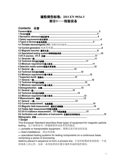
UNISONIC TECHNOLOGIES CO., LTD93334LINEAR INTEGRATED CIRCUITHIGH ENERGY IGNITION CIRCUITDESCRIPTIONThis device is designed to use the signal from a reluctor type ignition pickup to produce a well controlled output from a power darlington output transistor.FEATURES* Very Low Peripheral Component Count * No Critical System Resistors* Wide Supply Voltage Operating Range (4.0V ~ 24V) * Overvoltage Shutdown (30V)* Dwell Automatically Adjusts to Produce Optimum Stored Energy without Waste* Externally Adjustable Peak Current * Transient Protected Inputs and Outputs*Pb-free plating product number: 93334LORDERING INFORMATIONOrder NumberNormal Lead Free PlatingPackage Packing93334-S08-R 93334L-S08-R SOP-8 Tape Reel 93334-S08-T 93334L-S08-T SOP-8 TubePIN CONFIGURATIONOUTC S 2V CCI LSENS GNDPOWER GNDS 1BLOCK DIAGRAM AND TYPICAL APPLICATIONFigure 1ReluctorPickup1.35HComponent ValuesPickup Series resistance = 800Ω±10% @ 25℃, inductance= 1.35H @ 1.0kHz @ 15VrmsCoil Leakage L=0.6mH, primary R=0.43Ω±5% @ 25℃, primary L=7.5mH ~ 8.5mH @ 5.0AR L Load resistor for pickup=10Ω±20%R A, R B Input buffer resistors provide additional transient protection to the already clamped inputs=20k±20%C1, C2For reduction of high frequency noise and spark transients induced in pick-up and leads; optional and non-criticalR BAT Provides load dump protection (but small enough to allow operation at V BAT =4.0V) =300Ω±20% CFilter Transient filter on V CC, non-criticalC DWELL Stores reference, circuit designed for 0.1µF±20%R GAIN R GAIN/R D1 sets the DC gain of the current regulator =5.0k±20%R D2R D2/R D1 set up voltage feedback from R SR S Sense resistor (P D A G in thick film techniques) =0.075Ω±30%R DRIVE Low enough to supply drive to the output Darlington, high enough to keep V CE(SAT) of the I C below Darlington turn-on during load dump = 100Ω±20%, 5.0WR D1Starting with 35Ω assures less than 5.5A, increasing as required to set 5.5A R D1=(I O(PEAK) R S – V REF)/((V REF/R D2)-(1.4/R GAIN))-(≈100Ω)ABSOLUTE MAXIMUM RATINGSPARAMETER SYMBOLRATING UNIT 24Power Supply Voltage-Steady State Transient 300ms or less V CC 90V300 mAOutput Sink Current-Steady State Transient 300ms of less I OUT(SINK)1.0 A1.05 WPower Dissipation Derate above 25°C P D12 mW/°C Junction Temperature T J +125 °C Operating Temperature T OPR -20~+85 °C Storage Temperature T STG -40 ~ 150 °C Note 1. Absolute maximum ratings are those values beyond which the device could be permanently damaged. Absolute maximum ratings are stress ratings only and functional device operation is not implied. 2. The device is guaranteed to meet performance specification within 0 ~+70 operating temperature range and assured by design from -20 ~+85 . ELECTRICAL CHARACTERISTICS (V CC = 13.2V DC , circuit of Figure 3, unless otherwise specified) PARAMETER SYMBOL TEST CONDITIONS MIN TYP MAX UNITV BAT =4.0V DC 3.5 V BAT =8.0V DC 7.2V BAT =12.0V DC 10.4 Internal Supply Voltage, Pin 6 V CC V BAT =14.0V DC11.8VDCV BAT =4.0V DC 3.0 3.4 V BAT =6.0V DC 4.0 5.2V BAT =8.0V DC 4.6 5.3Ignition Coil Current Peak,Cranking RPM 2.0Hz ~ 27HzI PEAK V BAT =10.0V DC 5.15.4 A PEAKF =33Hz 5.1 5.5 F =133Hz 5.1 5.5F =200Hz 4.2 5.4F =267Hz 3.4 4.4 Ignition Coil Current Peak, Normal RPMI PEAK F =333Hz 2.7 3.4 A PEAK F =33Hz 7.5 14.0F =133Hz 5.0 5.9F =200Hz 4.0 4.6F =267Hz 3.0 3.6 Ignition Coil On-Time, Normal RPM RangeT ON F =333Hz 2.3 2.8ms Shutdown VoltageV BAT 25 30 35 V DCTurn-on 360Input Threshold (Static Test) V THR Turn-off 90mV DCInput Threshold Hysteresis V HYS 75 mV DCTurn-on 1.8Input Threshold (Active Operation)V THR Turn-off 1.5 V DCTotal Circuit Lag from ts (Figure 1) until Ignition Coil Current Falls to 10%60 120 µs Ignition Coil Current Fall Time (90% ~ 10%)4.0 µs V BAT =10V DC120V BAT =30V DC280Saturation Voltage IC Output (Pin 7) (R DRIVE = 100Ω)V CE(SAT)V BAT =50V DC540 mV DC Current Limit Reference, Pin 8 V REF120 160 190 mV DCLGNITION COIL CURRENT VERSUS FREQUENCY / PERIOD333I O U T (A )52001331010070152050253330msFrequency, f (Hz)。