Hydrocontrol先导阀
先导阀作用
先导阀作用
先导阀是一种常见的控制阀之一,主要用于控制流体的压力和流量。
它在工业领域具有广泛的应用,包括石油、化工、冶金、电力等行业。
首先,先导阀的作用在于控制系统的压力。
当系统压力超过设定值时,先导阀会自动打开,将多余的压力释放出去。
这可以防止系统压力超过最大承受能力,对设备造成损坏和安全隐患。
其次,先导阀还能调节系统的流量。
通过改变先导阀的开启程度,可以控制流体通过先导阀的速度和量。
这对于需要精确控制流量的工艺过程非常重要,可以保证系统的稳定性和生产效率。
此外,先导阀还可以用来控制系统的方向。
根据不同的需求,先导阀可以将流体引导到不同的管道或设备中。
这使得工艺流程能够更加灵活和高效,提高了系统的适应性和操作性。
除了以上的基本作用外,先导阀还可以配合其他控制元件使用,实现更复杂的控制功能。
例如,可以与传感器和执行机构相结合,实现自动化控制系统。
先导阀还可以与液压缸、液压电机等组合使用,实现液压传动系统的高效运行。
此外,先导阀还有一些特殊的作用。
例如,利用先导阀的泄压功能,可以实现能源的节约。
当系统压力超过设定值时,先导阀会自动打开,将多余的压力释放出去,减少能源的消耗。
这在一些对能源要求较高的系统中非常有用。
总而言之,先导阀作为一种常见的控制阀,具有多种作用和应用。
它可以控制系统的压力和流量,调节流体的方向,实现复杂的控制功能,提高系统的适应性和操作性。
同时,它还能实现能源的节约,为各行各业的生产和运营提供了重要的支持。
先导阀工作原理
先导阀工作原理先导阀是一种常见的控制装置,广泛应用于液压系统中。
它的作用是通过控制液压油的流动来控制执行元件的运动。
本文将详细介绍先导阀的工作原理,包括其结构、工作原理和应用领域。
一、先导阀的结构先导阀普通由阀体、阀芯和弹簧组成。
阀体是先导阀的外壳,起到固定和保护内部元件的作用。
阀芯是先导阀的核心部件,负责控制液压油的流动。
弹簧则用于提供阀芯的弹性力。
二、先导阀的工作原理先导阀的工作原理可以简单地分为两个阶段:控制阶段和工作阶段。
1. 控制阶段在控制阶段,当液压系统启动时,液压油从入口进入先导阀的阀体内。
通过阀芯上的通道和孔道,液压油进入阀芯的控制腔。
同时,弹簧提供的压力将阀芯向上推动,使阀芯上的密封圈与阀体上的密封面接触,阻挠液压油流动。
2. 工作阶段在工作阶段,当系统需要执行元件运动时,控制信号通过管道传递给先导阀。
控制信号作用于阀芯的控制腔,使阀芯受到力的平衡。
当控制信号的力大于弹簧提供的力时,阀芯开始下移,与阀体上的密封面分离,打开通道。
液压油从入口流向出口,进而控制执行元件的运动。
三、先导阀的应用领域先导阀广泛应用于各种液压系统中,特殊是需要精确控制和调节的系统。
以下是一些先导阀的应用领域示例:1. 工业机械:先导阀可用于控制液压缸、液压马达和液压阀等执行元件的运动。
2. 汽车工业:先导阀可用于汽车的制动系统、悬挂系统和变速器系统等。
3. 农业机械:先导阀可用于农业机械的液压系统,如拖拉机的液压升降装置和液压转向系统等。
4. 航空航天:先导阀可用于飞机和航天器的液压系统,如起落架的控制和舵面的调节等。
5. 海洋工程:先导阀可用于船舶和海洋平台的液压系统,如船舶的舵机和起重机的控制等。
总结:通过以上对先导阀工作原理的详细介绍,我们可以了解到先导阀是一种控制装置,通过控制液压油的流动来控制执行元件的运动。
先导阀的结构包括阀体、阀芯和弹簧,其工作原理可以分为控制阶段和工作阶段。
先导阀广泛应用于各种液压系统中,包括工业机械、汽车工业、农业机械、航空航天和海洋工程等领域。
先导阀工作原理
先导阀工作原理先导阀是一种常用的液压元件,广泛应用于各种液压系统中。
它的主要作用是控制液压系统中其他阀门的开闭动作,起到调节和控制液压系统工作压力的作用。
本文将详细介绍先导阀的工作原理,包括其结构、工作过程和应用场景。
一、先导阀的结构先导阀一般由阀体、阀芯、弹簧、控制孔和密封件等组成。
阀体是先导阀的外壳,用于固定阀芯和其他零部件。
阀芯是先导阀的核心部件,它的运动决定了阀门的开闭状态。
弹簧用于提供阀芯的复位力,使阀芯在没有外力作用时能够回到初始位置。
控制孔是用来控制液压油的流动方向和流量大小的通道。
密封件则起到防漏和密封的作用。
二、先导阀的工作过程先导阀的工作过程可以分为两个阶段:压力调节阶段和流量调节阶段。
1. 压力调节阶段当液压系统中的压力超过预设值时,压力油通过控制孔进入先导阀,推动阀芯向下运动。
阀芯下移后,阀门打开,使液压油流回油箱,从而降低系统压力。
当系统压力降低到预设值以下时,压力油不再进入先导阀,阀芯受到弹簧力的作用回到初始位置,阀门关闭,停止液压油流回油箱。
2. 流量调节阶段在压力调节阶段完成后,液压系统需要一定的流量来满足工作需求。
此时,控制孔中的压力油进入先导阀,推动阀芯向下运动。
阀芯下移后,阀门打开,液压油从系统进入工作部件,起到传动和控制的作用。
当需要减小流量时,压力油不再进入先导阀,阀芯受到弹簧力的作用回到初始位置,阀门关闭,停止液压油流入工作部件。
三、先导阀的应用场景先导阀广泛应用于各种液压系统中,特别是对压力和流量要求较高的场合。
以下是一些常见的应用场景:1. 工程机械在挖掘机、装载机、推土机等工程机械中,先导阀用于控制液压系统的动作,如控制液压缸的伸缩、旋转和提升等。
2. 冶金设备在冶金设备中,先导阀用于控制液压系统的压力和流量,如控制液压油缸的升降、夹紧和释放等。
3. 注塑机在注塑机中,先导阀用于控制液压系统的压力和流量,如控制注塑模具的开合和注塑材料的流动等。
4. 模具机械在模具机械中,先导阀用于控制液压系统的动作,如控制模具的开合、顶出和退回等。
先导阀工作原理
先导阀工作原理先导阀是一种常见的液压元件,它在液压系统中起到了重要的作用。
本文将详细介绍先导阀的工作原理,包括其结构组成、工作过程、工作原理和应用领域等方面的内容。
一、先导阀的结构组成先导阀主要由阀体、阀芯、弹簧、控制腔和进、出口等组成。
阀体是先导阀的外壳,通常由铸铁或铸钢制成,具有较高的强度和耐腐蚀性。
阀芯是先导阀的核心部件,通常由铜制成,具有良好的导热性和导电性。
弹簧则用于控制阀芯的位置,使其能够根据系统需求进行开关操作。
控制腔则是用于控制阀芯的压力和流量的空间。
二、先导阀的工作过程1. 静止状态:在液压系统未工作时,先导阀处于静止状态。
此时,阀芯被弹簧推向阀座,阀口关闭,液压系统处于关闭状态。
2. 工作状态:当液压系统开始工作时,液压油从进口进入控制腔,通过对控制腔内压力的调节,使得阀芯受到压力的作用,克服弹簧力,从而使阀芯移动,阀口打开。
3. 控制信号:先导阀通常通过电磁线圈或手动操作来接收控制信号,控制信号的改变会导致阀芯位置的改变,从而实现对液压系统的控制。
三、先导阀的工作原理先导阀的工作原理主要是通过调节阀芯的位置来控制液压系统的压力和流量。
当控制信号改变时,阀芯的位置也会相应改变,从而改变阀口的开启程度,进而改变液压系统的工作状态。
通过调节控制腔内的压力,可以控制阀芯的位置和阀口的开启程度。
当控制腔内的压力增大时,阀芯受到的压力增大,阀口开启程度增大,从而增加液压系统的压力和流量;当控制腔内的压力减小时,阀芯受到的压力减小,阀口开启程度减小,从而减小液压系统的压力和流量。
四、先导阀的应用领域先导阀广泛应用于各种液压系统中,特别是需要对压力和流量进行精确控制的系统中。
例如,先导阀常用于液压机械、工程机械、冶金设备、船舶和航空航天等领域。
在这些领域中,先导阀能够根据系统的需求,精确地控制液压系统的压力和流量,保证系统的正常运行。
总结:先导阀是一种常见的液压元件,通过调节阀芯的位置来控制液压系统的压力和流量。
先导阀工作原理
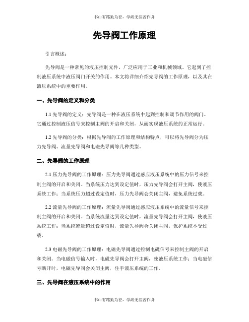
先导阀工作原理引言概述:先导阀是一种常见的液压控制元件,广泛应用于工业和机械领域。
它起到了控制液压系统中液压阀门开关的作用。
本文将详细介绍先导阀的工作原理,以及其在液压系统中的重要作用。
一、先导阀的定义和分类1.1 先导阀的定义:先导阀是一种在液压系统中起到控制和调节作用的阀门。
它通过控制液压信号来控制主阀的开启和关闭,从而实现液压系统的正常运行。
1.2 先导阀的分类:根据先导阀的工作原理和结构特点,可以将先导阀分为压力先导阀、流量先导阀和电磁先导阀等几种类型。
二、先导阀的工作原理2.1 压力先导阀的工作原理:压力先导阀通过感应液压系统中的压力信号来控制主阀的开启和关闭。
当系统压力达到设定值时,压力先导阀会打开主阀,使液压系统工作;当系统压力超过设定值时,压力先导阀会关闭主阀,避免系统过载。
2.2 流量先导阀的工作原理:流量先导阀通过感应液压系统中的流量信号来控制主阀的开启和关闭。
当系统流量达到设定值时,流量先导阀会打开主阀,使液压系统工作;当系统流量超过设定值时,流量先导阀会关闭主阀,保护系统不受过载。
2.3 电磁先导阀的工作原理:电磁先导阀通过控制电磁信号来控制主阀的开启和关闭。
当电磁信号输入时,电磁先导阀会打开主阀,使液压系统工作;当电磁信号断开时,电磁先导阀会关闭主阀,住手液压系统的工作。
三、先导阀在液压系统中的作用3.1 控制主阀的开启和关闭:先导阀通过感应液压信号来控制主阀的工作状态,从而实现液压系统的开启和关闭。
3.2 保护液压系统的安全:先导阀能够根据系统压力和流量的变化,及时控制主阀的开启和关闭,避免系统过载和损坏。
3.3 提高液压系统的工作效率:通过合理调节主阀的开启和关闭时间,先导阀可以提高液压系统的工作效率,减少能源的浪费。
四、结论先导阀是液压系统中重要的控制元件,其工作原理是通过感应液压信号来控制主阀的开启和关闭。
不同类型的先导阀根据其工作原理和结构特点进行分类,包括压力先导阀、流量先导阀和电磁先导阀等。
华申马丹尼先导式调节阀安全操作规定
华申马丹尼先导式调节阀安全操作规定前言先导式调节阀是一种重要的工业控制装置,能够实现流量自动控制。
华申马丹尼是一家领先的调节阀制造商,其生产的先导式调节阀广泛应用于各个领域。
本文将介绍华申马丹尼先导式调节阀的安全操作规定,以保证使用的安全性和有效性。
引言华申马丹尼的先导式调节阀由电极式或气动式调节阀、电动机或气动机构、位置信号检测器和控制器等部件组成。
在使用前,用户需要阅读并理解华申马丹尼的操作手册,并按操作规定进行使用。
安全操作规定1. 安装1.在安装前,用户应检查阀门和管路连接,确保连接联接处没有弯曲、壳体维修痕迹和猛烈碰撞;2.严格按照安装步骤进行操作,在安装过程中必须避免水分、油脂和灰尘等物质进入设备内部;3.电极式先导式调节阀在安装时,应注意正确连接阀门和控制器之间的线路。
2. 启动1.在启动前,用户应确保电源线路正确连接并接地;2.检查预设参数和工作条件是否匹配,如有不匹配的情况应解决后再启动;3.启动时应先使阀门缓慢升降,以便调整位置控制器,然后才能进行正式调节。
3. 调节1.调节过程中应严格按照操作手册要求进行操作,遵守操作流程;2.严禁在设备运行中对设备进行拆卸或维修,如需在设备运行中进行检修,应进行严格的工作票系统操作;3.在调节过程中应根据实际情况适时调整设备的控制参数,以保证设备工作的有效性和安全性。
4. 停机1.停机前应先关闭控制器输出信号,使先导式调节阀处于关闭状态;2.如果长时间停机,应该关闭主电源和控制气源,以免造成设备损坏。
总结本文介绍了华申马丹尼先导式调节阀的安全操作规定,通过遵守这些规定可以有效地保护设备的安全性和有效性。
在使用先导式调节阀时,用户应该阅读操作手册并按规定进行正确操作,同时注意保护设备不受水分、油脂和灰尘等污染物的侵害。
我们希望用户能够认真遵守这些规定,确保先导式调节阀的安全性和有效性。
先导阀工作原理范文
先导阀工作原理范文先导阀是一种常用于液压系统中的控制元件,它用于控制主阀或液控阀的开启和关闭。
先导阀能够根据输入信号的变化,控制液压系统中的流量和压力,从而实现对液压系统的控制。
先导阀的工作原理主要包括以下几个方面:1.先导阀的结构:先导阀通常由驱动电磁螺线管、阀芯和弹簧组成。
驱动电磁螺线管通过磁铁产生磁场,使得阀芯受到磁力的作用,从而改变阀芯的位置。
同时,弹簧也起到保持阀芯在一些位置的作用。
2.先导阀的工作过程:当输入信号作用于驱动电磁螺线管时,产生的磁力使得阀芯移动。
阀芯的位置决定了流体通道的开启和关闭状态。
一般情况下,阀芯的上、下两个端口分别与液体供应和回油管道相连,中间的孔则与控制阀相连。
当阀芯移动到一些位置时,可使得控制阀的通道打开或关闭,从而控制液体的流量和压力。
3.先导阀的控制方式:先导阀的控制方式主要有电磁控制和压力控制两种。
在电磁控制方式下,驱动电磁螺线管受到输入信号的作用,产生磁力,使得阀芯移动。
而在压力控制方式下,阀芯受到液压力的作用,直接改变阀芯的位置。
4.先导阀的功能:先导阀在液压系统中具有很重要的功能。
它能够根据输入信号的变化,实现对液压系统的流量和压力的控制。
当输入信号发生变化时,先导阀能够迅速响应,改变液压系统中的流量和压力,从而实现对液压系统的控制。
总之,先导阀作为液压系统中的一种重要控制元件,能够根据输入信号的变化,迅速改变液压系统中的流量和压力,从而实现对液压系统的控制。
它的工作原理主要包括结构、工作过程、控制方式以及功能。
在实际应用中,先导阀广泛应用于各种工业设备和机械系统中,起到了至关重要的作用。
先导阀工作原理动画
先导阀工作原理动画先导阀是一种常用的液压元件,它在液压系统中起着非常重要的作用。
在液压系统中,先导阀通过控制液压油的流动方向和流量大小,来实现对液压执行元件的控制。
那么,先导阀是如何工作的呢?接下来,我们通过动画的形式来详细了解一下先导阀的工作原理。
首先,我们来看一下先导阀的结构。
先导阀通常由阀芯、阀套、弹簧、阀体等部件组成。
当液压油进入先导阀时,会对阀芯施加压力,使得阀芯产生相对位移,从而改变阀芯与阀套之间的相对位置,从而改变液压油的流动通道,实现对液压系统的控制。
在先导阀工作时,液压油首先进入先导阀的控制腔,通过控制腔的压力来控制阀芯的运动,从而改变液压油的流动通道。
当控制腔的压力发生变化时,阀芯会产生相应的位移,从而改变液压油的流动方向和流量大小,实现对液压系统的控制。
此外,先导阀还可以通过控制阀芯的位置来调节阀口的开启大小,从而改变液压油的流量大小。
当阀芯向左移动时,阀口的开启大小会增大,液压油的流量也会增大;当阀芯向右移动时,阀口的开启大小会减小,液压油的流量也会减小。
通过这种方式,先导阀可以实现对液压系统的精确控制。
在液压系统中,先导阀的工作原理可以通过动画形式展现出来,让人们更直观地了解先导阀的工作过程。
通过动画,可以清晰地展示先导阀的结构和工作原理,帮助人们更好地理解先导阀在液压系统中的作用。
总的来说,先导阀通过控制液压油的流动方向和流量大小,来实现对液压执行元件的控制。
在液压系统中,先导阀扮演着非常重要的角色,它的工作原理也是非常复杂的。
通过动画的形式展示先导阀的工作原理,可以帮助人们更直观地了解先导阀的结构和工作过程,为液压系统的设计和维护提供参考。
- 1、下载文档前请自行甄别文档内容的完整性,平台不提供额外的编辑、内容补充、找答案等附加服务。
- 2、"仅部分预览"的文档,不可在线预览部分如存在完整性等问题,可反馈申请退款(可完整预览的文档不适用该条件!)。
- 3、如文档侵犯您的权益,请联系客服反馈,我们会尽快为您处理(人工客服工作时间:9:00-18:30)。
remote control range Servocontrols are control devices for the remote control of variable displacement pumps (hydrostatic transmissions) and flow rate direc-tional control valves. The precise and adequate use of all types of applications is ensured by high sensitivity, numerous adjustament curves and a low operating force.The remote control range Hydrocontrol is part of a consolidated tra-dition of development and production with innovative spirit of design in production processes. This permits offering a complete range of controls able to cater for the many different needs of end users.The cast-iron body together with the top quality of the steels used and most suitable heat treatments make this new range of hydraulic controls a forerunner in terms of sturdiness, reliability, ergonomics and smooth control.A global partner for innovative solutionshydraulic remote control Hydraulic remote controls that Hydrocontrol work by means of direct pressure reducing valve. They are especially sitable for remote-controlling distributors, pumps and motors, in small space thus ensuring high performances, quick and reliable responses both on mobile machinery and on industrial equipment. Hydrocontrol range includes different hydraulic remote controls that are manufactured using proper material whose processing is carried out with techno-logy methods, the most sophisticated tests and inspections, thus assuring a product at high reliability, suitable for strictest and exacting works.foot pedalThe wide range of foot controls, available in a variety of configurations, allows the best choice of product to be made in both functional and dimensional terms. The different models offer several solutions when it comes to hydraulic con-nection layout – always guaranteeing simple, straightforward installation. The new HC-RCS and HC-RCT series also include different foot control types, with special care applied to their ergonomic and design features.general Specification - hydraulic remote control and foot pedalMaximum input pressure 100 bar 1450 PSIMaximum back pressure on tank line 3 bar 43,5 PSIMaximum flow on ports 12 l/min 3 GPMHysteresis < 1 bar < 14,5 PSIHydraulic fluid MIneral oil HL, HM (o HLP DIn 51524)fluid temperature range -20°C / +80°Cfluid viscosity range 10 ÷ 300 cStMax contamination level 9 (nAS 1638) - 20/18/15 (ISO 4406:1999)Recommended filtration b 10 > 75 (ISO 16889:2008)LEakage (singol port) 3 cc/min (with 50 bar of pressure)Body material Cast ironSurface coating Zin plated (According to international standards2000/53/CE RoHS)Plunger material Stainless steel Plunger guide material Brass hydraulic remote control and foot pedal operating principleHydraulic remote controls and foot pedals works according to the principle of direct-acting pressure reducing valves. In rest position, the Joystick lever or kit pedal is held in neutral by return spring; inlet port P is closed and ports are connected to tank port T. By selecting control lever, plunger compresses return spring and reaction spring through cam mechanism; consequently it shifts spool and opens connection holes between inlet port P and service ports. This causes a pressure increase on service ports that is proportional to the control lever stroke and the reaction spring.HandleCam mechanismPlungerReturn springReaction spring Metering spool 1-2-3-4 = PortsP = Inlet portT = Tank port 1234T PSupply unitSupply unit range is used when oil is needed at a pressure that is lower than the pressure of primary circuit and wi-thout installing an auxiliary pump. It has been manufactured in order to feed hydraulic remote control or to adjust other equipment such as pumps and motors. It works by means of direct pressure reducing valves and it is usually provided with an accumulator in order to ensure, at any time, a certain number of moves even if the primary circuit is in a condition of emergency of failure: it is olso used to increase the switching efficiency. In order to avoid the accu-mulator depletion, the circuit that works at low pressure is protected by an adjustable main relief valve connected in the supply unit and by a check valve.general SpecificationS - Supply unitMaximum input pressure 350 bar 5000 PSIPressure on u port line 10 - 70 bar 145 - 1000 PSIMaximum back pressure on tank line 3 bar 43,5 PSIMinimum pressure in P1 10 bar 145 PSIHysteresis < 1 bar < 14,5 PSIHydraulic fluid Mineral oil HL, HM (o HLP DIn 51524)fluid temperature range -20°C / +80°Cfluid viscosity range 10 ÷ 300 cStMax contamination level 9 (nAS 1638) - 20/18/15 (ISO 4406:1999)Recommended filtration b 10 > 75 (ISO 16889:2008)Accumulator precharge pressure 10 bar 145 PSIMaximum working pressure accumulator 210 bar 3000 PSIMaximum allowed pressure ratio ≤ 6/1Capacity on service port u (without accumulator) 8 l/min 2 GPMWeight accumulator (0,35 l) 3 kgWeight accumulator (0,75 l) 2,5 kgWeight accumulator (1,50 l) 5,7 kgBody material Cast ironSurface coating Zinc plated (According to International standards 2000/53/CE RoHS)Because of the small dimensions and working on the same adjusting screw, this valve has the possibility of setting both the pressure reducing valve and the main relief valve. Main relief valve pressure setting is higher than about 10 bar if compared to the pressure reducing valve - see the pressure setting diagram. Supply unit may be installed in any mounting position but the accumulator should be as far as possible from heat sources.Supply unit operating principleThe purpose of supply unit HC-Su and HC-SE is to fit hydraulic remote controls in an hydraulic system working at high pressure with reduced flow at a low pressure. Operating principle is that of a direct acting pressure reducing valve. High pressure fluid from the main circuit is routed through ports P1, P2 and P3: pressure is decreased to the value required for supplying the hydraulic controls by means of a pressure reducing valve that directs the necessary fluid to the control via port (u). Supply units are fitted with an accumulator that satisfies short term peak power demands and is a source of emergency power should the main circuit pressure fail. To avoid the accumulator discharge, low pressure circuit is protected both by the adjustable main relief valve inside the cartridge of the pressure reducing valve and by the check valve. To start the hydraulic system, a backpressure of at least 10 bar on service port (P) has to be applied when the accumulator is discharged.P3AccumulatorReducing valve (U)Check valveP2P1U TStandard layout draWingShydraulic remote control input With auXiliary pumpStandard layout draWingS hydraulic remote control input With Supply unit coming from the main circuitAll information and diagrams in this catalogue refer to a mineral base oil Vg46 at 50°C temperature(32 cSt kinematic viscosity).thread codeSPorts dimensions are indicated by an ordering code, common throughout the range of remote control made byHydrocontrol. The following tables highlight the available threads.The specifications detailed in this catalogue show standard products. Special applications are available to order subject to contacting our Engineering Department for an estimate. The data and specifications indicated are to be considered a guide only and Hydrocontrol S.p.A. reserves the right to in-troduce improvements and modifications without prior notice. Hydrocontrol is not responsible for any damage caused by incorrect use of the product.general indeX 12 hc-rcX2 axis single lever remote controlTechnical specifications, applications, dimensionsOrder exampleControl kit classificationLever rod classificationBody arrangement18 hc-rcy2 axis single lever remote control reducedoperating forceTechnical specifications, applications, dimensionsOrder example20 hc-rcl2 axis single lever remote control withelectromagnetic detentTechnical specifications, applications, dimensionsElectromagnetic detent technical specifications22 hc-rcl32 axis lever + sisgle axis lever remotecontrol with electromagnetic detentTechnical specifications, applications, dimensionsElectromagnetic detent technical specifications24 hc-rcmStackable single axis levers remote controlTechnical specifications, applications, dimensionsOrder exampleControl kit classificationLever rod classificationBody arrangement30 hc-rcBSingle axis levers two modulesremote controlTechnical specifications, applications, dimensionsOrder exampleControl kit classificationLever rod classificationBody arrangement36 hc-rcpfoot pedal 2 service ports with side portsand reduced body heightTechnical specifications, applications, dimensionsOrder examplePedal kit classificationBody arrangement40 hc-rcffoot pedal lower portsTechnical specifications, applications, dimensionsOrder examplePedal kit classificationBody arrangement44 hc-rcddouble foot pedal lower portsTechnical specifications, applications, dimensionsOrder examplePedal kit classificationgeneral indeX48 hc-rcSfoot pedal lower portsTechnical specifications, applications, dimensionsOrder examplePedal kit classificationControl kit classificationStandard and narrow body classification54 hc-rctdouble foot pedal lower portsTechnical specifications, applications, dimensionsOrder examplePedal kit classificationControl kit classificationStandard and narrow body classification60 hc-rcVhydraulic remote control one service portTechnical specifications, applications, dimensionsOrder exampleControl kit classificationBody arrangement64 hc-Su/SeSupply unitTechnical specifications, applications, dimensionsOrder exampleSupply unit classificationAccumulator classificationDiagram for pressure setting, pressure reducing valve,main relief valveBody arrangement72 meteering curve classificationMeteering curve (type A - type B - type C - type D)Meteering curve for foot pedal (RCS - RCT)Meteering curve for hydraulic remore control (RCL - RCY)79 return spring classification80 handles classificationHandle “A - B - C - D”Handle “f”Handle “S”Handle “T”92 general conditions and patentshc-rcX - 2 axis single lever remote controlHydraulic remote control HC-RCX belongs to wide range of Hydrocontrol’e Remote Control; the lever’s anti-swaying system and the ergonomic handle provides great sensitivity while manoeuvring and makes his use very comfortable for the operator. Low operating efforts, low energy consumption and low maintenance make these hydraulic remote controls HC-RCX ideal for piloting remote control directional valves, variable displacement pumps and motors, auxilia-ry valves, frictions and hydraulic brakes.technical specificationsMax pressure: 100 bar Oil capacity: 12 l/minWeight: 2,5 kgapplicationsMini-excavators, Mini steer loaders, Backhoe loaders,Wheel loaders, Tractors, Boom mowersdimensionsTP1 2 3 4HYDRAULIC SCHEMAtype:RCX product type1) control claSSification: 1.1 03 control type 2) metering curVe: 2.1 a01 curve type 3) return Spring: 3.1 ma return spring type4) handle claSSification: 4.1 f handle type 4.2 05f front buttons arrangement 4.3 00r rear buttons arrangement 4.4 (2) handle position compared to ports 5) leVer rod claSSification: 5.1 Wf lever rod type 5.2 53 lever rod length 6) Body arrangement: 6.1 ra body specification 6.2 g02 body threadhc-rcX: 03 - a01 - ma - f 05f 00r (2) - Wf53 - ra g02Ordering row 2 and 3, must be repeated for each portcomplete sample: hc-rcX 03 a01 ma a01 ma a01 ma a01 ma f 05f 00r 2 Wf53 ra g021) control claSSification: (pag. 14)01 Return spring in neutral02 R eturn spring in neutral with detent in only one service port 03 Return spring in neutral with square bellows for straight lever rod 04R eturn spring in neutral with square bellows for bent lever rod2) metering curVe: (pag. 72)a 01 Linear metering curve with step B 01 Linear metering curve without step c 01 Broken line metering curve with step d 01Broken line metering curve without step3) return Spring: (pag. 79)ma Preload 25 n End stroke load 48 n mB Preload 14 n End stroke load 27 n mc Preload 73 n End stroke load 135 n mdPreload 89 nEnd stroke load 169 n4) handle claSSification: (pag. 80)a Without micro-switchB With micro-switch to closec With micro-switch to close with detentd With dual micro-switch f Ergonomic handle g Ergonomic handleS Ergonomic handle slim kSpherical handle5) leVer rod claSSification: (pag. 15)Levers depends on the handle and on the required control:Wf53 Straight standard lever for “f” handle Wg51 Bented standard lever for “f” handle 6) Body arrangement: (pag. 17)ra g02 Standard Body (g 1/4 ports)ra u02 Standard Body (9/16”-18 unf ports)rB g02 Body with shuttle valve for translation (g 1/4 ports)rB u02Body with shuttle valve for translation (9/16”-18 unf ports)hc-rcX order examplecontrol kit classification All controls installed on the remote control HC-RCX are interchangeable. Lever rod type must be choosen according to different control kit (see quick reference guide pag.15-16).The controls shown correspond to standard configurations; for different applications contact our Commercial Dept.lever rod classificationThe lever rod kits applied to all the HC-RCX hydraulic remote controls designed by Hydrocontrol change according to the type of control used and, above all, the type of handle. for improved clarity, all the possible lever rod configura-tions divided according to handle are listed here below. Straight and curved lever rods are available in several lengths and dimensions.Body arrangementThe remote hydraulic HC-RCX body has two versions: standard body and body with shuttle valve for translation.The set-up for translation applications (code: RB) includes a flanged plate with internal shuttle valves allowing a single service port control to be split between two ports. In this way, action on the lever will generate two separate pressure signals, allowing dedicated machine translation devices to be controlled.As an alternative to the “RB01” version, other set-ups are available with different flow restrictor diameters and confi-gurations on the service ports;for more information contact our Commercial Dept.hc-rcy - 2 axis single lever remote control reduced operating forceThe new HC-RCY hydraulic remote control is an evolution of the HC-RCX model. It adds to the variety of options and solutions offered by HC-RCX with an upgraded hydraulic control system, allowing the operating comfort to be impro-ved; the reduced-diameter control spool allows the required operating effort to be reduced by approximately 30%, without affecting the control, hysteresis and accuracy characteristics of this device.technical specificationsMax pressure: 100 bar Oil capacity: 12 l/minWeight: 2,5 kgapplicationsMini-excavators, Mini steer loaders, Backhoe loaders,Wheel loaders, Tractors, Boom mowersdimensionsTP1 2 3 4HYDRAULIC SCHEMAtype:RCY product type1) control claSSification: 1.1 03 control type 2) metering curVe: 2.1 a01 curve type 3) return Spring: 3.1 mB return spring type4) handle claSSification: 4.1 f handle type 4.2 03f front buttons arrangement 4.3 00r rear buttons arrangement 4.4 (2) handle position compared to ports 5) leVer rod claSSification: 5.1 Wf lever rod type 5.2 53 lever rod length 6) Body arrangement: 6.1 ra body specification 6.2 g02 body threadhc-rcy: 03 - a01 - mB - f 03f 00r (2) - Wf53 - ra g02Ordering row 2 and 3, must be repeated for each portcomplete sample: hc-rcy 03 a01 mB a01 mB a01 mB a01 mB f 03f 00r 2 Wf53 ra g021) control claSSification: (pag. 14)01 Return spring in neutral02 R eturn spring in neutral with detent in only one service port 03 Return spring in neutral with square bellows for straight lever rod 04R eturn spring in neutral with square bellows for bent lever rod2) metering curVe: (pag. 77)a 01 Linear metering curve with step B 01 Linear metering curve without step c 01 Broken line metering curve with step d 01Broken line metering curve without step3) return Spring: (pag. 79)ma Preload 25 n End stroke load 48 n mB Preload 14 n End stroke load 27 n mc Preload 73 n End stroke load 135 n mdPreload 89 nEnd stroke load 169 n4) handle claSSification: (pag. 80)a Without micro-switchB With micro-switch to closec With micro-switch to close with detentd With dual micro-switch f Ergonomic handle g Ergonomic handleS Ergonomic handle slim kSpherical handle5) leVer rod claSSification: (pag. 15)Levers depends on the handle and on the required control:Wf53 Straight standard lever for “f” handle Wg51 Bented standard lever for “f” handle 6) Body arrangement: (pag. 17)ra g02 Standard Body (g 1/4 ports)ra u02 Standard Body (9/16”-18 unf ports)rB g02 Body with shuttle valve for translation (g 1/4 ports)rB u02Body with shuttle valve for translation (9/16”-18 unf ports)hc-rcy order examplercl - 2 axis single lever remote control with electromagnetic detentHC-RCL is a remote control specifically designed for Wheel Loaders application. Based on the design of HC-RCX, it is used for two axis control (typically boom and bucket). It includes the function of electromagnetic detent to hold the lever at the end of the stroke: this feature is requested on loaders to allow the operator to start driving while boom and bucket functions are still moving.technical specificationsMax pressure: 40 bar Oil capacity: 12 l/minWeight: 2,9 kgapplicationsWheel loaders Skid steer loaderdimensionsLenght min. under fixing flange: 650 mm(electromagnetic control - Deutsch connector DT04-6P)Lenght min. under fixing flange: 500 mm (lever buttons - NO Connector)1234T P7Ø90Ø107Ø107Ø6.520°20°67.59528367.520°20°104104HOLDER HOLE DIMENSIONA 6-pole Deutsch DT04-6P connector is always used notwithstanding the number of required electromagnetic detents.The drawing here below shows the wiring of the solenoids assembled on the service ports 2, 3 and 4.The Deutsch DT06-6S connector counterpart can be supplied on request by quoting the order code 487200906.electromagnetic detent technical specificationSupply voltage 12 Vdc +/-20% 24 Vdc +/-20% Resistance at 20°C22W94WPower at 20°C 7WDuty ratingED100% Coil insulation plass (IEC 85)HConnectorDeutsch DT04-6PConnector protection (En 60529)IP67136425Deutsch Connector (DT04-6P)magnetic detent n.4magnetic detent n.2magnetic detent n.3rcl3 - 2 axis lever + sisgle axis lever remote control with electromagnetic detentHC-RCL3 is a remote control specifically designed for Wheel Loaders application. The compact design combines in a single body the two axis control (for boom and bucket) with a third axis (for auxiliary function). Electromagnetic detent is available on all ports. A security electrovalve to activate the remote control is available on request.technical specificationsMax pressure: 40 bar Oil capacity: 12 l/minWeight: 4,8 kgapplicationsWheel loadersdimensions(electromagnetic control - Deutsch connector DT04-6P)A 6-pole Deutsch DT04-6P connector is always used notwithstanding the number of required electromagnetic detents.The drawing here below shows the wiring of the solenoids assembled on the service ports 2, 3 and 4.The Deutsch DT06-6S connector counterpart can be supplied on request by quoting the order code 487200906.electromagnetic detent technical specificationSupply voltage 12 Vdc +/-20% 24 Vdc +/-20% Resistance at 20°C22W94WPower at 20°C 7WDuty ratingED100% Coil insulation plass (IEC 85)HConnectorDeutsch DT04-6PConnector protection (En 60529)IP67136425Deutsch Connector (DT04-6P)magnetic detent n.4magnetic detent n.2magnetic detent n.3The single-axis remote control is available without any detents, with electromagnetic detent or with mechanical detent.optionshc-rcm Stackable single axis levers remote controlHydraulic remote control HC-RCM belongs to the wide range of Hydrocontrol products. Low operating efforts, low energy consumption and low maintenance make these hydraulic remote controls HC-RCM ideal for piloting remote control directional valves, variable displacement pumps and motors, auxiliary valves, frictions and hydraulic brakes. Each hydraulic remote control is assembled with n.2 tie rod kits which include a tie rod, two nuts and two washers.It can be assemble up to 12 working sections.technical specificationsWorking section number: 1 - 12Max pressure: 60 bar Oil capacity: 12 l/min Weight HC-RCM/1: 1,5 kgTie rod clamping torque: 14 nmapplicationsMini steer loaders, Backhoe loaders, TractorsdimensionsT1P 2112.553912031.826°30’26°30’203959564.55037.5Ø6.25(177)HYDRAULIC SCHEMAPT1 2 1 2 1 2 1 238.539 39 39 19.53922 6.5X Y5970type:RCM product type/1 working section number1) control claSSification: 1.1 01 control type 2) metering curVe: 2.1 a01 curve type 3) return Spring: 3.1 ma return spring type 4) handle claSSification: 4.1 m handle type 5) leVer rod claSSification: 5.1 We lever rod type 5.2 95 lever rod length 6) Body arrangement: 6.1 ra body specification 6.2 g02 body threadhc-rcm/1: 01 - a01 - ma - m - We95 - ra g02Ordering row 2 and 3, must be repeated for each portcomplete sample: hc-rcm/1 01 a01 ma a01 ma a01 m We95 ra g021) control claSSification: (pag. 26)01 Return spring in neutral02 Stroke end mechanical detent in position 1 and 203 Stroke end mechanical detent in position 104 Stroke end mechanical detent in position 22) metering curVe: (pag. 72)a 01 Linear metering curve with step B 01 Linear metering curve without step c 01 Broken line metering curve with step d 01 Broken line metering curve without step3) return Spring: (pag. 79)ma Preload 25 n End stroke load 48 n mB Preload 14 n End stroke load 27 n mc Preload 73 n End stroke load 135 n mdPreload 89 nEnd stroke load 169 n4) handle claSSification: (pag. 80)a Without micro-switchB With micro-switch to closec With micro-switch to close with detentd With dual micro-switch m Impugnatura standard5) leVer rod claSSification: (pag. 28)Levers depends on the handle and on the required control:We95 Leva standard per impugnatura M (95 mm)We165 Leva standard per impugnatura M (165 mm)6) Body arrangement: (pag. 29)ra g02 Standard Body (g 1/4 ports)ra u02Standard Body (9/16”-18 unf ports)hc-rcm order examplecontrol kit classification All controls installed on the remote control HC-RCM are interchangeable.Lever rod type must be choosen according to different control kit (see quick reference guide pag. 29).The controls shown correspond to standard configurations; for different applications contact our Commercial Dept.microswitches specificationsDirect current load resistive: 5 a / 30 VdcDirect current load inductive: 3 a / 250 VacAlternative current load resistive: 5 a / 30 VdcAlternative current load inductive: 2 a / 250 Vaclever rod classification The lever rod kits applied to all the HC-RCM hydraulic remote controls designed by Hydrocontrol change according to the type of control used and, above all, the type of handle. for improved clarity, all the possible lever rod configura-tions divided according to handle are listed here below. Straight and curved lever rods are available in several lengths and dimensions.Handles type “A-B-C-D” are only available with HC-RCM/1. To set up an HC-RCM remote control with any number of sections between 2 and 12, an intermediate plate must be used identified by the order code RP.order example rcm/3 with “rp” intermediate plate HC-RCM/3: 01-A01-MA-A WA70-RA g02 - rp - 01-A01-MA-A WA70-RA g02 - rp - 01-A01-MA-A WA70-RA g021) fIRST SECTIOn:2) intermediate plate:3) SECOnD SECTIOn:4)intermediate plate:5) THIRD SECTIOn:Climping torque: 14 NmFirst sectionIntermediate plate (RP)Second sectionIntermediate plate (RP)Third sectionBody arrangementThe hydraulic remote control HC-RCM has only one setting body, the only variable is represented by a different threadhc-rcB Single axis levers two modules remote controlHydraulic remote control HC-RCB belongs to the wide range of Hydrocontrol. Low operating efforts, low energy con-sumption and low maintenance makes these hydraulic remote controls HC-RCB ideals for piloting remote control direc-tional valves, variable displacement pumps and motors, auxiliary valves, frictions and hydraulic brakes. Each hydraulic remote control is assembled with n.2 tie rod kits including a tie rod, two nuts and two washers.technical specificationsWorking section number: 2Max pressure: 60 bar Oil capacity: 12 l/minWeight: 3,2 kgTie rod clamping torque: 14 nmapplicationsMini skid loaders, Backhoe loaders, Tractorsdimensions3920°20°Ø 125Ø 108731.8953205926°30’26°30’78 6.564.55370Ø 6.2537.55064.5112.56(177)921122T1P 2HYDRAULIC SCHEMA T1 2 1 2Ptype:RCB product type1) control claSSification: 1.1 01 control type 2) metering curVe: 2.1 a01 curve type 3) return Spring: 3.1 ma return spring type 4) handle claSSification: 4.1 m handle type 5) leVer rod claSSification: 5.1 Wp lever rod type 5.2 110 lever rod length 6) Body arrangement: 6.1 ra body specification 6.2 g02 body threadhc-rcB: 01 a01 ma m Wp110 - 01 a01 ma m Wp110 - ra g021) control claSSification: (pag. 32)01Return spring in neutral02 Stroke end mechanical detent in position 1 and 203 Stroke end mechanical detent in position 104Stroke end mechanical detent in position 22) metering curVe: (pag. 72)a 01 Linear metering curve with step B 01 Linear metering curve without step c 01 Broken line metering curve with step d 01Broken line metering curve without step3) return Spring: (pag. 79)ma Preload 25 n End stroke load 48 n mB Preload 14 n End stroke load 27 n mc Preload 73 n End stroke load 135 n mdPreload 89 nEnd stroke load 169 n4) handle claSSification: (pag. 80)a Without micro-switchB With micro-switch to closec With micro-switch to close with detentd With dual micro-switch m Impugnatura standard5) leVer rod claSSification: (pag. 34)Levers depends on the handle and on the required control:WV75 Standard lever for handle type A-B-C-D (75 mm)Wp110 Standard lever for handle type M (110 mm)Wt110 Standard lever for handle type M (110 mm) (only for control 05 and control 12)6) Body arrangement: (pag. 35)ra g02 Standard Body (g 1/4 ports)ra u02Standard Body (9/16”-18 unf ports)hc-rcB order exampleOrdering row 1,2,3,4 and 5, must be repeated for each working section。