The Hardware Muon Trigger Track Finder Processor in CMS- Specification and Method
Han 接触器手动紧固工具及相关产品参数说明书

90·1ContentsPage Hand crimping tools for Han ® standard contacts .....................................90.4Hand crimping tools for fibre optic contacts .............................................90.9Hand crimping tools for Han-Fast ® Lock contacts ...................................90.10Hand crimping tools for wire end ferrules ................................................90.11Hand crimping tools for D-Sub contacts ..................................................90.12Hand crimping tools for coaxial contacts .................................................90.13Pneumatic crimping tool ..........................................................................90.15Hydraulic crimping tools for Han ® TC high current contacts ....................90.16Crimping machine TC-C01 ......................................................................90.18Crimping machine TK-M ..........................................................................90.20Crimping machine BK ..............................................................................90.22Panel punch .............................................................................................90.24Assembly tools ........................................................................................90.25Removal tools ..........................................................................................90.29Stripping tools ..........................................................................................90.32ToolsHan ® tools1) TK-M basic machine 09 98 000 6900 is required2) depending on the wire3) only with modification 09 98 503 6900Features• Basic unit of compact construction for pre-stripped wires (stranded wire)• Easy handling due to well-arranged design• for individual, turned male and female contacts• Selective processing of male and female contacts• Automatic contact feed• Reproducible, top quality gas-tight crimp connections• Non-slip, anti-vibration adjustable feet for setting the height • Low noise level• With carrying handle• Removable electric and pneumatic supply connections • Maintenance interval counter• Minimal setup effort• Stepless adjustment of the crimping depth• Low follow-up costs for maintenance and repair• Easy replacement of wearing components DetailsNominal voltage, max. 230 VNominal frequency 50 HzPower consumption ca.0.2 kWPressure ca.6 barControl system PLCWork cycle trigger FootswitchWork cycle 1 sNoise level ca.62 dBCrimp type Four-point crimpingContact feed Vibratory bowl feedStroke counters Resettable daily counter and permanent counterDimensions 345 x 230 x 400 mmWeight ≥24 kgPack contents:2.0 m connection cable and grounding plug, 2.0 m pneumatic hose,quick-release coupling and N6 plugin nipple, footswitch,carrying handle,operating instructions,declaration of conformityTools90Features• Basic unit of compact construction• Fast stripping and crimping in one operating step• Easy handling due to well-arranged design• Touchscreen controlling• for individual, turned male and female contacts• Selective processing of male and female contacts• Contact magazine with filling control• Reproducible, top quality gas-tight crimp connections• Infinitely variable adjustment parameters (stripping depth, stripping length, crimping depth, crimp contact feed rate)• Rotatable vibration feeder and actuator in basic unit• Low noise level• for oil-free compressed air• Minimal setup effort• Low maintenance costs DetailsDrive electro-pneumaticNominal voltage, max. 230 VNominal frequency 50 HzPower consumption ca.0.75 kWPressure ca.6 barCompressed air connection 3 dm³ / work cycleControl system PLCWork cycle trigger sensorWork cycle 1.5 sNoise level <70 dBCrimp type Four-point crimpingContact feed Vibratory bowl feedStroke counters Resettable daily counte, total counter, operating hours, maintenance counter and quantity preselection Dimensions 580 x 470 x 470 mmWeight <60 kgPack contents:one mounted interchangeable unit,2.0 m connection cable and grounding plug,2.0 m pneumatic hose with plug-in nipple N6,plug gauges for setting the crimping,centering bush for positioning the plug gauges,draw for insulation remains,drawer for holding the contacts when the magazine is emptied, tool set for setting,1 set of stripping blades,operating instructions,declaration of conformityToolsCrimping machine TK-M90Features• Fast stripping and crimping in one operating step• Easy handling due to quick change tool and stripper• Suitable for standard D-Sub crimp contacts• Selective processing of male and female contacts• Hand wheel for manual adjustments• Maintenance-friendly through needle bearing rail• Automatic exhaust of the isolation remainders• Reproducible, top quality gas-tight crimp connections• With crimp force monitor• Setting parameters with raster rotary button (depth of insula-tion stripping, length of insulation stripping, crimping heigth on wire, crimping heigth on isulation, wire retainer position, band thrust and wire position in the crimp contact)• Non slip and anti-vibration feet• Low noise level• for oil-free compressed air• Low maintenance costs• V-blades for special wires on request DetailsDrive electro-pneumaticNominal voltage, max. 230 VNominal frequency 50 HzPower consumption 0.75 kWPressure 6 barControl system PLCStripping device type 514Suction apparatus 2000.0900.20Work cycle trigger sensorWork cycle 0.35 sNoise level 85 dBIllumination integrated tool light 20001326Motor speed 440 –2000 rpmStroke counters Resettable daily counter and permanent counter Dimensions 690 (with a contact reel: 1400) x 420 x 430 mm Weight <72 kgPack contents:with role owner and guide plate,2.0 m connection cable and grounding plug,2.0 m pneumatic hose with plug-in nipple N9,oiler bottle for the lubricating of the crimping contacts,tool set for setting,1 set of stamps for wire and isolation-crimp,1 anvil one-piece for wire and isolation-crimp,1 set of stripping blades,1 litre of contact oil,operating instructions,declaration of conformityTools90。
TRIGGERCAM 基础入门指南说明书

BASIC START GUIDE WWW.TRIGGERCAM.COSelect & fit the required insert over yourriflescope eyepiece. There should be a gapof approximately 2mm.STEP 1:STEP 3:STEP 2:Slide the correct insert into the TRIGGER CAM so that the insert slot is aligned with the slot of the TRIGGERCAMMount the TRIGGER CAM over the riflescope eyepiece and slightly tighten the mounting screw until the TRIGGERCAM is fixed to your riflescope.Switch on the TRIGGER CAM. Press and hold the power button for 2 seconds. Power button (red arrow) Wi-Fi button (blue arrow). To switch on the Wi-Fi. Press and hold the Wi-Fi button for 2 seconds.STEP 4:Connect to the TRIGGER CAM WI-FI networkon your mobile device. The password for thecamera is 12345678. STEP 5:STEP 6:Search for TRIGGER CAM on Google play or the App store and download the app for your mobile device. Connect to your camerathrough the mobile app.Remove the focus cap with the TRIGGER CAM tool.STEP 7:After mounting, the next step is to focus the TRIGGER CAM for your specific riflescope. Ensure your riflescope is set on the desired magnification preferred, and aim on a target at the distance on which your rifle is zeroed e.g. 100 metres. Through using the live streaming function on the app turn the focus until the image is clear. [TIP: Focus your TRIGGER CAM on a high magnification, if you then move to lower magnification it will remain in focus. If you focus on a low magnification and want to move higher, it will lose focus faster.] STEP 8:STEP 8: (continue)Image not in focusImage in focusGrey arrow - Focus RingBlue arrow - Charge PortRed arrow - SD CardSTEP 9:Once your device is focussed, set the orientation of the camera so that the crosshairs are perfectly aligned. This can be done through live streaming function on your smart phone (SEE INSTRUCTIONS OF STREAMING BELOW).STEP 10:Your TRIGGER CAM is now ready• Recording can be done on either the TRIGGER CAMitself or via the TRIGGER CAM smart phone app. Afterthe TRIGGER CAM is switched on, push the ON buttonuntil the beep sound is heard, the TRIGGER CAM is nowrecording. This recording is saved on the SD card that isinserted in the TRIGGER CAM. To stop the recording, pushthe ON button again until the beep sound is heard.• The red light indicates that your TRIGGER CAM is chargingwhen plugged in. When the red ligt changes to green,your unit is fully charged.power bank to your unit.QUICK FACTSTHE APP PROVIDES USERS WITH THE FOLLOWING INTERACTIVE FUNCTIONS:DISCLAIMERTRIGGERCAM trading under, EYECAM TECHNOLOGIES (PTY) LTD 2014/010477/07, and their shareholders, directors, officers, employees, sub-contractors or agents or affiliates in whole or in part, shall not be liable in any way whatsoever for any loss, injury or damage (including but not limited to consequential or special damages or loss of profits) of whatsoever nature, and whether or not caused by the negligence (gross or otherwise) of EYECAM TECHNOLOGIES (PTY) LTD and their shareholders, directors, officers, employees, sub-contractors or agents arising out of, incidental to, orin connection in any way with the use or instalment of our products. EYECAM TECHNOLOGIES (PTY) LTD and their shareholders, directors, officers, employees, sub-contractors or agents are hereby released from any duty of care towards such customer, client or person. EYECAM TECHNOLOGIES (PTY) LTD shall have no liability of any nature whatsoever to any customer, client or person to whom purchase a product or from us. The waiver referred to above will be binding on the heirs, dependants, assignees, executors, trustees or other legal representatives of the customer, client or person who areusing, installing, testing or purchasing our products.。
Atomos Ninja V 快速入门指南说明书

ContentsIntroduction . . . . . . . . . . . . . . . . . . . . . . . . . . . . . . .3 Checklist . . . . . . . . . . . . . . . . . . . . . . . . . . . . . . . . .3 Y ou will also need . . . . . . . . . . . . . . . . . . . . . . . . .3 Getting started . . . . . . . . . . . . . . . . . . . . . . . . . . . .4 Connect and Power-up . . . . . . . . . . . . . . . . . . . .5 Physical features . . . . . . . . . . . . . . . . . . . . . . . . . .6 Format SSD Media . . . . . . . . . . . . . . . . . . . . . . . .8 T ouchscreen/User Interface . . . . . . . . . . . . . . .9 Connect and Edit . . . . . . . . . . . . . . . . . . . . . . . . .10 AtomX Accessories . . . . . . . . . . . . . . . . . . . . . .10 Warranty & Conditions . . . . . . . . . . . . . . . . . . . .112 NINJA V - Quick Start GuideThank you for purchasing the Atomos Ninja V, utilising professional HDMI 2.0 connectivity to record professional 4Kp60 and High frame rate HD to Apple ProRes and Avid DNxHR. The class leading AtomHDR monitor lets you visualize 10+ stops of dynamic range, with 1000nit brightness for daylight viewing and 10-bit processing for smooth gradations. With so many Recorder, Monitor, Playback & Edit features, please take the time to read through this Quick Start Guide and register your product for free updates and extended warranty.DOWNLOAD THE FULLNINJA V USER MANUAL /supportACTIVATE AVID LICENSE FOR DNxHD® and DNxHR®/activation EXTENDED 3 YR WARRANTY Register now to extend your warranty to 3 years from date of purchase. /registration HDMI CableTo support 4Kp60 recording please use cables that support HDMI 2.0 specification. Atomos have a range of 4Kp60 cables with die cast connectors and coiled cables in a range of lengths and connections (sold separately). See the full range of Atomos HDMI cables on our website: /hdmi-cablesSSD Drives and Docking StationWe test and approve SSD drives from the world’s leading media brands. There are specific approved drives depending on the resolution and frame rate you are capturing - for the full list of compatible drives please refer to: /drivesWe also have a range of Docking Stations suitable for use with Ninja V and compatible SSD media. Visit your nearest reseller or purchase online at: ChecklistYou will also need (sold separately)q 1 x Ninja V Recorderq 1 x Master Caddy IIq 1 x AC Power Adaptorq 1 x Battery Eliminatorq 1 x Quick Start GuideIntroductionNINJA V - Quick Start Guide 3BatteryYou can power the device using the supplied AC power supply and Battery Eliminator, but if you plan to use a battery we recommend you fully charge before use.We recommend using Atomos NP-F series batteries.Connect SSDBefore powering up the Ninja V unit, simply slide your selected disk intodisk slot (see page 7). To remove, ensure the unit is off and gentlyslide out. We strongly recommend SSD for optimal performance andrecording.IMPORTANT: Never remove the SSD whilst recording as this maycause data corruption.Introducing AtomX SSDminiAtomos has teamed with the world’s leading media manufacturers todesign SSD media that is better suited to our ever evolving RecorderMonitors.The new AtomX SSDmini is a little over 1/4 inch tall and 3” long. It isalso 20% shorter than traditional SSDs, yet keeps the standard SATAIII connector. It is backward compatible with previous Atomos devicesby adding a clever extension handle. These tiny, slimline SSDs area true innovation and our close drive partners Angelbird and SonyStorage Media Solutions Corporation are making custom versionsfor your Ninja!For more information about supported drives and accessories, visit:/drivesGetting started4 NINJA V - Quick Start GuideConnect and power-up BatteryNinja V has a single battery slot. To connect a compatible battery, place the battery in front of the retaining lug, align with theconnectors and slide the battery into the lock position.To connect the supplied Battery Eliminator, follow the same procedure and lock battery into position. Once the Battery Eliminator is in place, secure the supplied AC/DC power supply to the DC jack. Alternatively, the Ninja V unit can be powered via a D-Tap power source using D-Tap battery cable (ATOMDTPCB1).Touching the Battery icon in the top right of your screen will allow you to accurately see remaining battery life. Refer to the User Manual for more information.Expansion PortThe Ninja V features a built in Expansion Port that will soon enable- Synchronization control- I/O Expansion- Continuous Power Module(See page 7)DC jackSupplied Battery EliminatorP/N: ATOMDCA001NINJA V - Quick Start Guide 56 NINJA V - Quick Start Guidea. On/Off and Screen LockTo turn the Ninja V on, press the power button on the side of the unit. To shut down, hold the button for at least 4 seconds (until unit turns off).b. Remote Control/LANC and CalibrationOptionally control the Ninja V using LANC/Remote from your camera. Additionally, the Ninja V screen can be calibrated using the X-Rite i1Display Pro. To connect you will need a USB to serial cable. Refer to the AtomX accessory range. USB to serial cable (ATOMCAB004).c. HDMI In/OutHDMI input connection used to record to the Ninja V supports up to 4Kp60. HDMI Output connection provides a live loop out or play out when in Playback mode. Supports up to 4Kp60.d. Battery Release Button Press the release button and slide battery away from unit to remove. e. T ally LightRed Tally light on the rear of the unit indicates active recording. The Tally Light can be turned off in the menu options.f. Screw Holes / Mounts + Locking Pin Holes (Arri)3/8” screw hole with 1/4” adapter. Top and bottom.g. Disk SlotThe NinjaV is compatible with Master Caddy II media and also the latest AtomX SSDmini.Physical featuresf. 3/8” screw hole with 1/4” adapterf. 3/8” screw hole with 1/4” adaptera.On/Off and Screen Lock c. HDMI In c. HDMI Outb. Remoted. Battery releaseNINJA V - Quick Start Guide 7e. Tally lightf. 3/8” screw hole with 1/4” adapterf. 3/8” screw hole with 1/4” adapterd. Battery releaseg. Disk slotExpansion Port8 NINJA V - Quick Start GuideMain controlsThe Ninja V is controlled by a simple user-friendly touchscreeninterface. Pictured below is the home screen and main controls seen when the Ninja V is first powered up. Touching the icons will open menus for the relevant functions. Touch the settings icon located onbottom right to access more menus, or touch individual icons for specific settings such as timecode, audio, remaining disk space and more. For the most up-to-date information visit: /ninjav and click SUPPORT tabNINJA V - Quick Start Guide 9Connect and EditTo access and edit your recorded materialYou will require a USB 3.0 Docking Station or USB-C 3.1 Docking Station.These are available from your reseller, or visit to purchase the Docking Station that is best suited to your requirements.Connect the Docking Station to a Mac ® or Windows ® editingworkstation via USB 2.0 / USB 3.0 / USB-C 3.1 compatible port/s.When using USB 2.0, you may need to connect the second USB enough power is provided when using USB 2.0.Insert SSD it into the Docking Station. After a short wait your recorded video will become accessible as a standard external disk.NoticeCopyright © 2018 ATOMOS Global Pty Ltd (‘referred to as ATOMOS’). All rights reserved. All information in this document is subject to change without notice. No part of the document may be reproduced or transmitted in any form, or by any means, electronic or mechanical, including photocopying or recording, without the express written permission of ATOMOS. A reference to ATOMOS includes its related entities, subsidiaries and parent company.TrademarksNinja V / ATOMOS are registered trademarks of ATOMOS Pty Ltd. Apple, the Apple logo, AppleShare, AppleTalk, FireWire, iPod, iPod Touch, Mac, and Macintosh are registered trademarks of Apple Inc. Final Cut Pro, QuickTime and the QuickTime Logo are trademarks of Apple Inc. All other trademarks are the property of their respective holders. International Hardware Limited Warranty (1 Year Standard/3 Years if registered) ATOMOS warrants that:• The main product, not including the IPS screen, or any external accessories, will be free from defects in materials and workmanship for a period of 1 year from the date of purchase; or 3 years upon completion of product registration at • The TFT/LCD, batteries, case and master caddies will be free from defects in materials and workmanship for a period of 1 year from the date of purchase regardless of registration. This warranty is exclusively for the benefit of the original purchaser and is not assignable or transferable. If during the warranty period the product is shown to be defective ATOMOS may at its option: a) replace the goods or supply equivalent ones, b) repair the goods, c) pay the cost of replacing the goods or of acquiring equivalent ones and d)paying the cost of having the goods repaired; The customer must notify ATOMOS of any defect in the goods in writing prior to the expiry of the warranty periods set out above. The customer will be solely responsible for returning the goods to ATOMOS or its authorized distributor. Upon acceptance of a warranty claim by ATOMOS, where ATOMOS repairs or replaces the goods, it will be responsible for reasonable shipping costs incurred in sending the goods to the Customer, provided that customer is located in a country in which ATOMOS has an authorized distributor or repair center or agent.Warranty ExclusionsThis warranty applies only to defects in workmanship and does not cover defects caused by:• A failure to comply with the then current operating instructions issued by ATOMOS;• Neglect;• Improper or negligent acts or omissions;• Unauthorized repairs or attempted repairs;• Tampering with or modification of the goods;• Connection to incompatible equipment or power sources;• Exposure to water or weather;• Exposure to magnetic fields or corrosive liquids or substances;EXCEPT AS STATED IN THIS WARRANTY, ATOMOS, IT’S VENDORS, AGENTS, RESELLERS AND DISTRIBUTORS DISCLAIM IN THEIR ENTIRETY ALL OTHER WARRANTIES, EXPRESS OR IMPLIED, INCLUDING WITHOUT LIMITATION ALL WARRANTIES OF MERCHANTABILITY OR FITNESS FOR A PARTICULAR PURPOSE. THE REMEDIES OUTLINED IN THIS WARRANTY ARE THE EXCLUSIVE REMEDY A CUSTOMER HAS ARISING FROM DEFECTIVE GOODS WHICH ARE SUBJECT TO THE WARRANTY. ATOMOS DOES NOT WARRANT THAT THE GOODS WILL OPERATE IN A MANNER WHICH IS ERROR FREE, OR UNINTERRUPTED. THE GOODS ARE NOT INTENDED TO BE THE PRIMARY OR ONLY DATA STORAGE DEVICE FOR DATA – CUSTOMERS ARE SOLELY RESPONSIBLE FOR BACK UP AND PROTECTION OF DATA. Software License AgreementIMPORTANT, PLEASE READ CAREFULLY. THIS IS A LICENSE AGREEMENT.This ATOMOS software, related documentation, any included sample images and other files (the “Software”), is protected by copyright laws and international copyright treaties, as well as other intellectual property laws and treaties. The Software is licensed, not sold.This End User License Agreement (“EULA”) is a legal agreement between you (either an individual ora single entity) and ATOMOS with regard to the copyrighted Software provided with this EULA. Use of the Software provided to you by ATOMOS in whatever form or media, will constitute your acceptanceof these terms, unless separate terms are provided by the software supplier, in which case certain additional or different terms may apply. If you do not agree with the terms of this EULA, do not download, install copy or use the Software. By installing, copying or otherwise using the Software, you agree to be bound to the terms of this EULA. If you do not agree to the terms of this EULA, ATOMOS is unwilling to license the Software to you.1. Eligible licensees. This Software is available for license solely to purchasers of the ATOMOS Ninja V, who have purchased a unit manufactured by ATOMOS Ninja V and purchased through an ATOMOS authorized reseller, with no right of duplication or further distribution, licensing or sub-licensing.2. License Grant. ATOMOS grants you a personal, non-transferable and non-exclusive right to use the copy of the Software provided with this EULA. You agree you will not copy the Software except as necessary to use it with the ATOMOS Ninja V. You agree that you may not copy the written materials accompanying the Software. Modifying, reverse engineering, translating, renting, copying, transferring or assigning all or part of the Software or any rights granted hereunder, to any other persons or reverse engineering the hardware on which the Software runs, is strictly prohibited. The software is license, not sold. You acknowledge that no title to intellectual property in the Software is transferable to you. You further acknowledge that title and full ownership rights to the Software will remain the exclusive property of ATOMOS and/ or its suppliers, and you will not acquire any rights to the Software, except as expressly set forth above. All copies of the software will contain the same proprietary notices as contained in oron the Software. All title and copyrights in and to the Software (including but not limited to any images, animations, video, audio, text incorporated), the accompanying printed materials, and any copies of the Software are owned by ATOMOS or its suppliers.3. Reverse engineering. You agree that you will not attempt, and if you are a corporation, you will use your best efforts to prevent your employees and contractors from attempting to reverse compile, derive circuits, modify, translate or disassemble the Software and/or the ATOMOS Ninja V in whole or in part. Any failure to comply with the above or any other terms and conditions contained herein will result in the automatic termination of this license and the reversion of the rights granted hereunder by ATOMOS. ATOMOS reserves the right to terminate this license without prejudice to any additional recourse ATOMOS may have against you if you violate any of its terms and conditions.Warranty & Conditions 10 NINJA V - Quick Start GuideAtomos have a range of accessories tailored to usage with the Ninja V. Visit or your nearest Atomos reseller to discover the range of available accessories that will get you up and running enhance your production workflow.Batteries and power:- ATOMOS 5200mAh 4 Cell NPF Style Battery NP-770- ATOMOS 7800mAh 6 Cell NPF Style Battery NP-970- ATOMOS Fast Battery Charger with Multi plug PSU- ATOMOS Power Kit for all Atomos 5” & 7” Monitor Recorders Media: Master Caddy II- ANGELBIRD Master Caddy II 4K RAW SSD- G-TECHNOLOGY MasterCaddy II 4K SSD- ATOMOS Master Caddy II HDD/SSD Caddies x 5Media: SSDmini-AtomX SSDmini by ANGELBIRD (256GB, 500GB, 1TB)- AtomX SSDmini by SONY (500GB, 1TB, 2TB)Docking stations:- ATOMOS USB 2.0 & 3.0 Docking Station for Atomos Master Caddy - ANGELBIRD USB-C to SATA Media Reader- G-TECHNOLOGY ev Series Reader Atomos Master Caddy Edition (only compatible with SSDmini when using AtomX SSDmini Adaptor handle) Cables:- ATOMOS AtomFLEX HDMI 4K60p Full to Full (30cm/40cm/50cm) - ATOMOS AtomFLEX HDMI 4K60p Full to Micro (30cm/40cm/50cm) - HDMI Coiled cable 4Kp30 Full to Full (30cm/50cm)- HDMI Coiled cable 4Kp30 Full to Micro (30cm/50cm)© Atomos 2018. TM ® All trademarks and registered trademarks are the property of their respective owners.Visit Atomos online for full technical specifications, tutorials, camera compatibility, recommended SSDs and more.For more detailed instructions and important up-to-date information regarding Ninja V please download the complete Ninja V User Manual from:/support 。
施耐德电气低压配电产品选型指南说明书
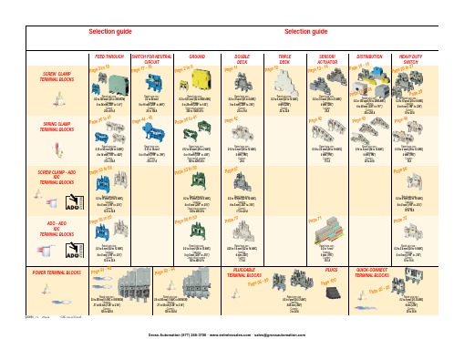
ABB EntrelecSommaireBU0402061SNC 160 003 C0205SummarySelection guide ....................................................................................page 1Screw clamp ........................................................................................page 2Feed through and ground terminal blocks .......................................................page 2 - 5 to 10Single pole, multiclamp terminal blocks..........................................................................page 4Feed through terminal blocks - Double-deck................................................................page 11Feed through terminal blocks - Triple-deck...................................................................page 12Three level sensor, terminal blocks without ground connection...................................page 13Three level sensor, terminal blocks with ground connection ........................................page 14Terminal blocks for distribution boxes, double deck + protection .......................page 15 - 16Interruptible terminal blocks for neutral circuit......................................................page 17 - 18Distribution : phase, ground terminal blocks .......................................................page 19 to 21Single pole or four pole distribution blocks..........................................................page 22 to 24Heavy duty switch terminal blocks with blade......................................................page 25 - 26Heavy duty switch terminal blocks with push-turn knob..............................................page 26Heavy duty switch terminal blocks with contact control pull lever...............................page 29Heavy duty switch terminal blocks with blade - Double-deck .....................................page 27Fuse holder terminal blocks for 5x20 mm (.197x.787 in.) and 5x25 mm (.197x.984 in.)or 6.35x25.4 mm (1/4x1 in.) and 6.35x32 mm (1/4x11/4 in.) fuse s.........................................page 28 - 29Fuse holder terminal blocks for 5x20 mm (.197x.787 in.) and 5x25 mm (.197x.984 in.) fuses -Double-dec k.....................................................................................................................page 27Terminal blocks for test circuits with sliding bridge ......................................................page 30Terminal blocks for metering circuits.............................................................................page 31ESSAILEC terminal blocks.............................................................................................page 32Safety connection terminal blocks ................................................................................page 33Miniblocks for EN 50045 (DIN 46277/2) rail ..........................................................page 34 - 35Spring clamp ......................................................................................page 36Angled terminal blocks - Feed through and ground .....................................................page 36Feed through and ground terminal blocks ...........................................................page 37 to 41Feed through terminal blocks - Double deck ................................................................page 42Terminal blocks for sensors / actuators ........................................................................page 42Terminal blocks for distribution boxes...........................................................................page 43Switch terminal blocks for neutral conductor........................................................page 44 - 45Heavy duty switch terminal blocks with blade..............................................................page 46Fuse holder terminal blocks for 5x20 mm (.197x.787 in.) and 5x25 mm (.197x.984 in.) fuse s....page 47Miniblocks Spring clamp ......................................................................................page 48 to 52ADO - Screw clamp ...........................................................................page 53Feed through and ground terminal blocks ...........................................................page 53 to 56Feed through and ground terminal blocks - Double-deck............................................page 57Heavy duty switch terminal blocks with blade..............................................................page 58Fuse holder terminal blocks for 5x20 mm (.197x.787 in.) and 5x25 mm (.197x.984 in.) fuse s ......page 59 - 60Miniblocks ADO - Screw clamp............................................................................page 61 to 65ADO - ADO .........................................................................................page 66Feed through and ground terminal blocks ...........................................................page 66 to 69Feed through and ground terminal blocks - Double-deck............................................page 70Terminal blocks for sensors / actuators ........................................................................page 71Heavy duty switch terminal blocks with blade..............................................................page 72Fuse holder terminal blocks for 5x20 mm (.197x.787 in.) and 5x25 mm (.197x.984 in.) fuse s ......page 73 - 74Miniblocks ADO - ADO .........................................................................................page 75 to 79Accessories ADO ...........................................................................................................page 80Power terminal blocks .............................................................page 81 to 84Quick-connect terminal blocks .................................................page 85 - 86Terminal blocks for railway applications ................................page 87 to 97Pluggable terminal blocks .....................................................page 98 to 100Accessories......................................................................................page 101Marking..................................................................................page 102 to 104GrossAutomation(877)268-3700··*************************PR30PR3.Z2PR3.G2PR5PR4PR1.Z2Rated wire size :Rated wire size :Rated wire size :Rated wire size :Mounting railsShield terminals forcollector barMarking tableHorizontal Rated wire size :0.5 to 16 mm² (22 to 8 AWG)Rated wire size :Rated wire size :Rated wire size :P a g e t o 29e30 t o 32ag e e3P a ge 8 t o 60a g e6t o 6574P a ge 7 t o 79P a ge 9P a g P a gGrossAutomation(877)268-3700··*************************2ABB Entrelecd010830402051SNC 160 003 C0205MA 2,5/5 - 2.5 mm² blocks - 5 mm .200" spacingAccessoriesGrossAutomation(877)268-3700··*************************3ABB Entrelec D010740402051SNC 160 003 C0205M 4/6 - 4 mm² blocks - 6 mm .238" spacingAccessoriesGrossAutomation(877)268-3700··*************************4ABB EntrelecD011030402051SNC 160 003 C0205M 4/6.3A - 4 mm² blocks - 6 mm .238" spacingM 4/6.4A - 4 mm² blocks - 6 mm .238" spacingGrossAutomation(877)268-3700··*************************5ABB Entrelec D010840402051SNC 160 003 C0205M 6/8 - 6 mm² blocks - 8 mm .315" spacingAccessoriesGrossAutomation(877)268-3700··*************************6ABB EntrelecD010850402051SNC 160 003 C0205M 10/10 - 10 mm² blocks - 10 mm .394" spacingAccessoriesGrossAutomation(877)268-3700··*************************7ABB Entrelec D010860402051SNC 160 003 C0205M 16/12 - 16 mm² blocks - 12 mm .473" spacingAccessoriesGrossAutomation(877)268-3700··*************************8ABB EntrelecD010870402051SNC 160 003 C0205M 35/16 - 35 mm² blocks - 16 mm .630" spacingGrossAutomation(877)268-3700··*************************M 95/26 - 95 mm² blocks - 26 mm 1.02" spacingM 70/22.P - 70 mm² ground block with rail contact - 22 mm .630" spacingSelection35 mm / 1.37"12 mm / 0.47"14-30 Nm / 124-260 Ib.in 1.2-1.4 Nm / 10.6-12.3 Ib.in1000600600415400400577070240 mm 2500 MCM 500 MCM 10 mm 2 6 AWG 6 AWG IEC UL CSANFC DIN0.5 - 160.5 - 100 AWG-600 MCM 2 AWG-500 MCM 50 - 30035 - 24018-6 AWGD 150/31.D10 - 150 mm² blocks - 31 mm 1.22" spacingCharacteristicsD 240/36.D10 - 240 mm² blocks - 36 mm 1.41" spacingSelectionWire size main circuit mm² / AWG VoltageV Current main circuit A Current outputARated wire size main circuit mm² / AWG Rated wire size outputmm² / AWG Wire stripping length main circuit mm / inches Wire stripping length output mm / inches Recommended torque main circuit Nm / Ib.in Recommended torque outputNm / Ib.inSolid Stranded Solid Stranded Wire size output mm² / AWG9.5 mm / .37"0.5-0.8 Nm / 4.4-7.1 Ib.in5003003003220204 mm 212 AWG12 AWG0.2 - 422-12 AWG 22-12 AWG 0.22 - 4IEC ULCSANFC DINCharacteristicsWire size mm² / AWGSolid Stranded D 4/6.T3 - 4 mm² blocks - 6 mm .238" spacingSelectionVoltage V CurrentARated wire sizemm² / AWG Wire stripping length mm / inches Recommended torqueNm / Ib.inM 4/6.T3.P - 4 mm² block - 6 mm .238" spacingD 2,5/6.D - 2.5 mm² blocks - 6 mm .238" spacingD 2,5/6.DL - 2.5 mm² blocks - 6 mm .238" spacingD 2,5/6.DPA1 - 2.5 mm² blocks - 6 mm .238" spacingD 2,5/6.DPAL1 - 2.5 mm² blocks - 6 mm .238" spacingD 4/6... - 4 mm² blocks - 6 mm .238" spacingD 4/6.LNTP - 4 mm² closed blocks - 17.8 mm .700" spacingMA 2,5/5.NT- 2.5 mm² block - 5 mm .200" spacingAccessories**SFB2 : 16 to 35 mm² 6 to 2 AWG H= 3 mm/.12"M 10/10.NT- 10 mm² block - 10 mm .394" spacingAccessories(1) Except for M 35/16 NT (closed block)*SFB1 : 0.5 to 35 mm² 18 to 2 AWG H= 7 mm/.28"**SFB2 : 16 to 35 mm² 6 to 2 AWG H= 3 mm/.12"MB 4/6... - 4 mm² blocks - 6 mm .238" spacingMB 6/8... - 6 mm² blocks - 8 mm .315" spacingMB 10/10... - 10 mm² blocks - 10 mm .394" spacingBRU 125 A - 35 mm² block - 27 mm 1.063" spacingBRU 160 A - 70 mm² block - 35.2 mm 1.388" spacingBRU 250 A - 120 mm² blocks - 44.5 mm 1.752" spacingBRU 400 A - 185 mm² block - 44.5 mm 1.752" spacingAccessoriesAccessoriesBRT 80 A - 16 mm² block - 48 mm 1.89" spacingBRT 125 A - 35 mm² block - 48 mm 1.89" spacingBRT 160 A - 50 mm² block - 50 mm 1.97" spacing9.5 mm / .37"0.5-0.6 Nm / 4.4-5.3 Ib.in4003003002010104 mm 210 AWG 12 AWG 0.5 - 422-10 AWG20-12 AWG0.5 - 2.5IEC ULCSANFC DINMA 2,5/5.SNB - 2.5 mm² blocks - 5 mm .200" spacingCharacteristicsM 4/6.SNB - 4 mm² blocks - 6 mm .238" spacingSelectionWire size mm² / AWGVoltage V CurrentARated wire sizemm² / AWG Wire stripping length mm / inches Recommended torqueNm / Ib.inSolid StrandedM 6/8.SNB - 6 mm² blocks - 8 mm .315" spacing - blade switchingSelectionAccessoriesM 4/8.D2.SF - for fuses 5x20 mm .197x.787 in. and 5x25 mm .197x.984 in. -4 mm² blocks - 8 mm .315" spacingM 4/6.D2.SNBT - 4 mm² blocks - 6 mm .238" spacing - blade switchM 4/8.SF- 4 mm² blocks - 8 mm .315" spacingM 4/8.SFL - 4 mm² blocks - 8 mm .315" spacing12 mm / .472"1.2-1.4 Nm / 10.6-12.3 Ib.in800(1)60060016252510 mm 210 AWG8 AWG0.5 - 1622-10 AWG 22-8 AWG 0.5 - 10IEC ULCSANFC DINCBD2SML 10/13.SF - for fuses 6.35x25.4 mm 1/4x1 in. and 6.35x32 mm 1/4x11/4 in. -10 mm² blocks - 13 mm .512" spacingSelectionAccessoriesCharacteristicsWire size mm² / AWGVoltage V CurrentARated wire sizemm² / AWG Wire stripping length mm / inches Recommended torqueNm / Ib.inSolid Stranded (1) Insulation voltage of terminal block - operating voltage : according to fuse.M 4/6.D2.2S2... - 4 mm² blocks - 6 mm .238" spacing11 mm / .43"0.8-1 Nm / 7.1-8.9 Ib.in50060030306 mm 28 AWG0.5 - 1022-8 AWG0.5 - 6IECULCSANFC DINM 6/8.ST... - 6 mm² blocks - 8 mm .315" spacingCharacteristicsWire size mm² / AWGVoltage V CurrentARated wire sizemm² / AWG Wire stripping length mm / inches Recommended torqueNm / Ib.inSolid Stranded M 6/8.STA - 6 mm² blocks - 8 mm .315" spacing(3)Only for M 6/8.STAM 4/6.ST- 4 mm² blocks - 6 mm .236" spacingBNT...PC...(2) Only for M10/10.ST-SnThe PREM IUM solution for testing the secondary circuits of current or voltage transformers.ESSAILEC, approved by the major electricity utilities, remains the premium choice for the energy market.Implemented in the transformers secondary circuits, ESSAILEC thanks to its intelligent “make before break” design eases and secures any intervention. Cutting the energy supply is avoided with zero risk for the operator.The plug and socket connection cuts cost installation as well as in-situ wiring errors. ESSAILEC is ideal for the wiring of sub-assemblies in the secondary circuits.ESSAILEC terminal blocksProtection relays,Protection relays,Testing :The ESSAILEC socket supplies energy to the protection or counting devices. The insertion of the test plug, which is connected to the measurement equipment, allows the testing of the devices, without perturbing the circuit.ESSAILEC blocks are well adapted to current or voltage measurement :-Current sockets with make before break contacts and pre-wired test plug for current measures-Voltage sockets with open contacts and pre-wired test plug for voltage measures-Up to 4 ammeters or 4 voltmeters connected to the test plugDistributing :The ESSAILEC plug is continuously mounted on the socket to supply current or voltage to secondary circuits sub assemblies.ESSAILEC blocks extreme versatility allow :-Safe current distribution with current socket with mobile contacts since the secondary circuit is not cut when plug is removed-Voltage or polarity distribution with dedicated voltage or polarity socket with closed contactESSAILEC is designed to offer :Great flexibility :-Connection multi contacts « plug and play »-Panel, rail, rack fixed mounting or stand-alone connector -Two wiring technologies, up to 10 mm²Extreme reliability :-Non symmetric blocks -Coding accessories -IP20 design -Locking system -Sealed coverR S T NFor technical characteristics and complete part numbers list, please ask for the ESSAILEC catalog10005006003225254 mm 21.65 mm²12 AWG 13 mm / .51"IECB.SCSANFC DINTS 50-180.5 - 0.8 Nm /4.4 - 7.1 Ib.in0.2 - 422-12 AWG0.22 - 40.5 - 1.50.28 - 1.6580050060041252562.512 AWG 13 mm / .51"0.8 - 1 Nm / 7.1 - 8.9 Ib.inIECB.S CSANFC DINTS 50-180.5 - 1020-12 AWG0.5 - 60.28 - 2.590050060046406510 mm 26 mm² 6 AWG 14 mm / .55"IECB.S UL/CSANFC DINTS 50-181.2 - 1.4 Nm / 10.6 - 12.3 Ib.in0.5 - 1620 - 6 AWG0.5 - 100.28 - 6M 4/6.RS - 4 mm² blocks - 6 mm .238" spacingCharacteristicsWire size mm² / AWGVoltage V CurrentARated wire sizemm² / AWG Wire stripping lengthmm / inches Recommended torque (screw)Nm / Ib.inSolid wire Stranded wire Solid wire Stranded wire Screw clampLugsM 6/8.RS - 6 mm² blocks - 8 mm .315" spacingCharacteristicsWire size mm² / AWGVoltage V CurrentARated wire sizemm² / AWG Wire stripping lengthmm / inches Recommended torque (screw)Nm / Ib.inSolid wire Stranded wire Solid wire Stranded wire Screw clampLugspending M 10/10.RS - 10 mm² blocks - 10 mm .394" spacingCharacteristicsWire size mm² / AWGVoltage V CurrentARated wire sizemm² / AWG Wire stripping lengthmm / inches Recommended torque (screw)Nm / Ib.inSolid wire Stranded wire Solid wire Stranded wire Screw clampLugspending SelectionAccessories(1) Only for block M 4/6.RS (4) For blocks M 4/6.RS and M 6/8.RS(2) Only for block M 6/8.RS(3) Only for block M 10/10.RSDR 1,5/4 - 1.5 mm² blocks - 4 mm .157" spacingDR 1,5/5... - 1.5 mm² blocks - 5 mm .200" spacing。
雷尼希亚RMP60机械工具接触测试探头系统说明书

• 2.4 GHz radio transmission, allows single system forworldwide use.• Interference-free channel hopping transmission.• No channel selection required. • RMP60 meets the radio regulations of:Europe: CE 0536! USA: FCC ID: KQGRMP60, FCC ID: KQGRMP60V2 FCC ID: KQGRMP60MV2 Japan: RMP60: 004NYCA0042, RMP60: 004NYCA0406 RMP60M: 004NYCA0407Canada: IC: 3928A-RMP60, IC: 3928A-RMP60V2Australia, China, Israel, New Zealand, Russia, Switzerlandand India.• Partner RMP60 and RMI systems allow interference-freemultiple probe installations.• The RMP60 is suitable for use with Renishaw single anddouble touch probing cycles.• User adjustable trigger force for long/cranked styli. • A weak link is included in each kit to protect the probein the event of excessive stylus overtravel, when using steel styli.• The RMP60 is a compact 3D touch-trigger probe(±X, ±Y , +Z sense directions) with radio transmission, used for workpiece set-up and inspection on small to large CNC machining centres and vertical turret lathes.• The RMP60 transmits omnidirectionally with a range of15 m (49.2 ft).• Ease of installation.• A standard battery life of 140 hours continuous use, orthe equivalent of approximately 100 days at 5 % usage is achievable. For applications requiring greater battery life, certain high capacity lithium thionyl chloride batteries can be used.• Repeatability, 1.0 µm (40 µin) is certified at480 mm/min (1.57 ft/min) with 50 mm stylus.• Probe switch on is user configurable between M code, spinor shank.• Probe switch off is user configurable between M code,time, spin or shank switch dependant on turn on method.StylusData sheet H-2000-2122-03-A A Tech Authoirty, Inc3857 Schaefer Ave, Ste C Chino, CA. 91710 (909)972-7520Operating envelope - RMP60/RMIThe RMP60 transmission envelope and range is shown below.The probe system should be positioned so that the optimum range can be achieved over the full travel of the machine’s axes including the tool magazine. Always face the RMI in the direction of the machine spindle and tool magazine. If the probe is not in range when in the tool magazine use spin or shank turn on.The RMP60 and RMI must be within a mutual operating envelope. The operating envelope shows line-of-sight performance. However, radio transmission does not require line-of-sight as long as any reflected radio path is less than the 15 m (49.2 ft) system operating range.RMP60 probeRange metres (feet)OPERATING AND SWITCH ON/OFF75°0°15°90°75°60°75°0°19 (0.75)50 (1.97)RMP60 dimensionsdimensions mm (in)ZData sheetRMP60 - radio probeBattery dead - at this stage probe status is forced open and the probe cycle will stop.System operationPrior to probe operation, it is imperative that the program selected to ‘drive’ the probe has been verified. Incorrect programming could result in damage to the machine, workpiece and probe system.The RMP60 probe operates in one of three modes:1. Stand-by mode - The RMP60 uses a small current,while waiting for a switch-on signal to be received.2. Operating mode - Activated by one of the methodsdescribed below. Signals are only transmitted by the probe in this mode and the probe is now ready for use.3. Configuration mode - Trigger Logic™ allows a numberof probe set-up options to be programmed, by triggering the probe when the batteries are inserted. Programmableoptions are described on the next page.Probe environmentPrimary application Inspection probe for machiningcentres Sense directions 5 way ±X ±Y +ZWeight (without a shank) with batteries without batteries901 g (31.79 oz) 855 g (30.16 oz)Trigger force using 50 mm (1.97 in) stylus low force direction factory settingX Y 0.75 N / 75 gf (2.65 ozf)Z 5.30 N / 530 gf (18.69 ozf)Trigger force using 50 mm (1.97 in) stylus high force directionX Y 1.4 N / 140 gf (4.94 ozf)Z 5.30 N / 530 gf (18.69 ozf)Max. spin speed 1000 rev/minOvertravel X Y 18°Z 11 mm (0.43 in)Sealing IPX8 (BS 5490, IEC 529)1 atmosphereRepeatability maximum 2σ value in any direction 1.0 µm (0.00004 in) is valid fortest velocity of 480 mm/min(1.57 ft/min) at stylus tip, usingstylus 50 mm (1.97 in) long.Probe specificationProbe status LEDsWhen operating the probe status LEDs give a visual indication of the probe state (triggered or seated) and battery condition.Multiple probe modeRMP60 can be user configured using T rigger Logic™ to allow multiple RMP60s to be used with a single RMI.Notes:Radio turn on cannot be used in multiple probe mode. RMP60s set to ‘mode-on’ can coexist alongside any number of RMP60’s set to ‘mode-off’.To allow multiple probes/single RMI in close proximity, 16 choices of ‘mode-on’ colours are available – each representing a different machine tool installation.Only one of the multiple probes per machine will need partnering as, by configuring multiple probes to a single‘mode-on’ choice, all probes have the same identification. The probe to be partnered is partnered after selection of multiple probe on mode.There is no limit to the number of probes that can be used with a single RMI as long as they all have the same ‘mode-on’ colour choice.All RMP60s are factory-set to ‘mode off’.The addition of further probe(s) into a single probe installation requires all probes to be re-configured to the same multiple probe ‘mode-on’ choice and the repartnering of one of the probes to the installed RMI.The addition of further probes (or replacements) into a multi probe installation is achieved simply by reconfiguration to the same ‘mode-on’ colour choice.Comprehesive details of how to set-up and change mutiple probe settings are included in the RMP60 installation and user's guide, H-2000-5219.RMP60/RMI Temperature Storage -10 °C to 70 °C (14 °F to 158 °F)Normal operating5 °C to 50 °C (41 °F to 122 °F)Notes:The RMP60 will be turned on after 1 sec in all modes.)After being turned on, the RMP60 must be on for a minimum of 1 sec (7 seconds for spin option) before being turned off. In radio on configuration (either radio on/radio off or radio on/time off) the RMP60 has a built-in hibernate mode. This saves battery life when the RMP60 is in stand-by and the RMI is un-powered (or out of range).The RMP60 goes into hibernate mode 30 sec after the RMI is un-powered (or out of range). When in this mode, the RMP60 checks for a powered RMI every 30 secs, if the RMI is found, the RMP60 goes from the hibernate mode to stand-by, ready for radio turn on.Probe switch on and offThe probe is switched on by one of the following options.All options are user configurable.RMP60 switch-on method.Switch-on options are configurable.RMP60 switch-off method.Switch-off options are configurable.1. Radio onRadio switch on is commanded by M code. (factory setting).1. Radio offRadio switch-off is commanded by M code. (factory setting).A timer automatically switches the probe off after 90 min from the last trigger, if not turned off by M code.2. Timer off (time out)The RMP60 will time out (12, 33 or 134 sec - user configurable) after the last probe trigger or reseat.2. Spin startSpin at 650 rev/min for 1 sec minimum (6 sec maximum).3. Spin stopSpin at 650 rev/min for 1 sec minimum (6 sec maximum).A timer automatically switches the probe off after 90 min from last trigger off.4. Timer off (time out)The RMP60 will time out (12, 33 or 134 sec - userconfigurable) after the last probe trigger or reseat.3. Shank switch5. Shank switch offBattery life expectancyTypical battery reserve lifeUsing the standard alkaline battery at 5% usage, typically the probe will continue to operate for approximately 1 week after a low battery warning is first indicated.Replace the batteries as soon as is practicable.Rechargeable batteries: either nickel metal hydride (NiMh) or nickel cadnium (NiCd) can be used, but expect a battery life of approximately 50% of the alkaline figures given in the table below.To achieve stated radio stand-by life, the RMP60 must be in-range of a powered partner RMI.Battery Shank/spin turn onRadio turn on Continuous useTwo AA type Stand-by life (days - typical)5% usage 72 minutes/day (days - typical)Stand-by life (days - typical)5% usage 72 minutes/day (days - typical)(hours - typical)Alkaline65010013065140Lithium ThionylChloride1300200260130280For applications requiring greater battery life, certain high capacity lithium thionyl chloride batteries can be used.Data sheetRMP60 - radio probe(Ø2.48)RMP60M is a special modular version of RMP60. It enables probe inspection of part features inaccessible to RMP60, by fitting selected adaptors and extensions as shown.RMP60M modular systemRMP60M dimensions40.75 50.00 / 100.00 / 150.00 66.25 (Ø2.48)100.00 / 150.00 / 200.00 50.50 (Ø2.48)66.25Parts list - Please quote the Part no. when ordering equipment.TypePart no.DescriptionRMP60A-4113-0001RMP60 probe with batteries, tool kit and user’s guide (factory set to radio on/radio off).RMP60M module A-4113-1003RMP60M probe with batteries, tool kit and user’s guide (factory set to radio on/radio off).Battery P-BT03-0005AA battery - Alkaline type supplied as standard with probe (two required).Battery P-BT03-0008AA battery - Lithium thionyl chloride (two required).Stylus A-5000-3709PS3-1C ceramic stylus 50 mm long with Ø6 mm ball.Weak link kit A-2085-0068Weak link (Part no. M-2085-0069 x 2) and 5 mm AF spanner.Tool kit A-4038-0304Probe tool kit comprising: Ø1.98 mm stylus tool, 2.0 mm AF hexagon key,2.5 mm AF hexagon key (x 2), 4 mm AF hexagon key, and shank grub screws (x 2).Diaphragm kit A-4038-0302RMP60 outer diaphragm.Battery cassette A-4038-0300RMP60 battery cassette assembly.Cassette seal A-4038-0301Battery cassette housing seal.Bobbin kit A-4038-0303Bobbin for shank switch (supplied with shank).RMI A-4113-0050RMI, side exit, with 15 m (49.2 ft) cable, tool kit and user’s guide.Mtg brkt A-2033-0830Mounting bracket with fixing screws, washers and nuts.Extension L100A-4038-1010RMP60M extension - 100 mm long.Extension L150A-4038-1027RMP60M extension - 150 mm long.Extension L200A-4038-1028RMP60M extension - 200 mm long.Probe module A-4038-1002RMP60M probe module assembly.RMP60/LP2 adaptor A-4038-0212RMP60M LP2 adaptor assembly.LPE1A-2063-7001LPE1 extension bar - 50 mm long.LPE2A-2063-7002LPE2 extension bar - 100 mm long.LPE3A-2063-7003LPE3 extension bar - 150 mm long.MA4A-2063-7600MA4 90° adaptor assembly.RMP60 user’s guide H-2000-5219RMP60 user’s guide.Styli –See brochure H-1000-3200 Styli and accessories.Software –See data sheet H-2000-2289 Probe software for machine tools.Shanks –See data sheet H-2000-2011 Shanks.RMI–See data sheet H-2000-2123 RMI.Renishaw plcNew Mills, Wotton-under-Edge, Gloucestershire GL12 8JR United KingdomT +44 (0)1453 524524F +44 (0)1453 524901E ***************© 2006 Renishaw plc. All rights reserved. Renishaw reserves the right to change specifications without noticeIssued 11.06 Part no. H-2000-2122-03-AFor worldwide contact details, please visit ourmain web site at /contact*H-2000-2122-03*。
Atomos Shinobi 7 快速启动指南说明书

ContentsThank you for purchasing the Atomos Shinobi 7, utilizingprofessional HD-SDI and HDMI connectivity to monitor up to professional 4Kp60 (via HDMI) and 1080p60 (via 3G-SDI). The class leading AtomHDR monitor lets you visualize 10+ stops of dynamic range, with 2200nits brightness for daylight viewing and 10-bit processing for smooth gradations. Please take the time to read through this Quick Start Guide and register your product for free updates.DOWNLOAD THE FULL SHINOBI 7 USER MANUAL /supportIntroductionIntroduction . . . . . . . . . . . . . . . . . . . . . . . .2Checklist . . . . . . . . . . . . . . . . . . . . . . . . . .3Y ou will also need . . . . . . . . . . . . . . . . . .3AtomX Accessories . . . . . . . . . . . . . . . .3Getting started . . . . . . . . . . . . . . . . . . . . .4Connect and Power-up . . . . . . . . . . . . .4Input . . . . . . . . . . . . . . . . . . . . . . . . . . . . . . .5Physical features . . . . . . . . . . . . . . . . . . .6T ouchscreen/User Interface . . . . . . . .8Monitor assist tools . . . . . . . . . . . . . . . .9Warranty & Conditions . . . . . . . . . . . . .10Notifications . . . . . . . . . . . . . . . . . . . . . .11Y ou will also need (sold separately)SDI CableSDI cables are robust physically and electrically. You should rarely have problems with signal transmission unless your cables are either damaged or too long. Please remember that SDI cables use locking connectors and will not simply pull out if they are pulled or tripped over. They are therefore a significant trip hazard, and also a hazard to your equipment, which may be damaged if the cables are mishandled or of a low grade. Please ensure you test and check your SDI cables; for longer runs cables of a Belden 1694A specification are recommended.HDMI CableAtomos have a range of HDMI cables with die cast connectors and coiled cables in a range of lengths and connections (sold separately).Checklistq 1 x Shinobi 7q 1 x AC Power Adaptor q 1 x Quick Start GuideAtomos have a range of accessories tailored to usage with the Shinobi 7. Visit your nearest Atomos reseller to discover the range of available accessories that will get you up and running enhance your production workflow.Batteries and power:- ATOMOS 5200mAh 4 Cell NPF Style Battery NP-770- ATOMOS 7800mAh 6 Cell NPF Style Battery NP-970- ATOMOS Fast Battery Charger with Multi plug PSU -ATOMOS Power Kit for all Atomos 5” & 7”Monitor RecordersCables:-ATOMOS AtomFLEX HDMI 4K60p Full to Full (30cm/40cm/50cm)-ATOMOS AtomFLEX HDMI 4K60p Full to Micro (30cm/40cm/50cm)- HDMI Coiled cable 4Kp30 Full to Full (30cm/50cm)- HDMI Coiled cable 4Kp30 Full to Micro (30cm/50cm)Connect and power-upBatteryShinobi 7 provides dual battery slots that combined with the DC input allow for continuous power operation. With both batteries connected Shinobi 7 will draw power from them simultaneously, if a battery is removed it will automatically switch over to the second battery or the DC power input. This allows you to swap out a depleted battery without having to shut down the monitor.Touching the battery icons in the top right of your screen will allow you to accurately see remaining battery life. Refer to the User Manual for more information.AC/DC PowerAlternatively power your Shinobi from mains power using the included AC Power Adaptor. Simply attached the AC power adaptor to mains power, carefully attach to the DC port on theShinobi 7 and rotate the locking nut to secure.The DC input port can also be used with the optional AtomosDTAP to DC cable (ATOMDTPCB2) to supply power to the Shinobi 7 from a DTAP power output.Battery indicators will show that no batteries are attached andthe unit is being powered via DC power input.PowerYou can power the device using the supplied AC power supply, but if you plan to use a battery we recommend you fully charge before use.We recommend using Atomos NP-F series batteries.Getting startedInputAccess Input MenuINT o access the Input Menu simply tap the INPUT (IN) area located in the top left of the Shinobi screen. Choose signal - HDMI or SDISOURCEDisplays the input source currently connected to the Shinobi, simply tap to toggle between HDMI & SDI inputs. Y ou can have both HDMI and SDI inputs connected at the same time and use this menu to toggle between active inputs.HDMIBattery releaseOn/Off Remote/CalibrationportHeadphone/audio outSDCardSlot1/4” screw hole1/4” screw holeOn/Off and Screen LockT o turn the Shinobi 7 on, press the power button. T o shut down, hold the button for at least 4 seconds (until unit turns off).SDI InThe SDI inputs support 3G in both level A and B standards. SDI OutThis is for connection to an external monitor or other device with an SDI input. It carries a loop-through of the incoming SDI (limited to 3G 1080p60) or HDMI signal in monitor and standby mode. HDMI InHDMI input connection to the Shinobi 7 supports up to 4Kp60. HDMI OutHDMI output connection from the Shinobi 7 supports up to 4Kp60. Remote Calibration PortThe Shinobi 7 screen can be calibrated using the X-Rite i1Display Pro. T o connect you will need a USB to serial cable. (ATOMCAB004) Battery ReleasePress the release buttons and slide batteries upwards to remove. Headphone / Audio outStandard 3.5mm audio output for audio monitoring.Screw Holes / Mounts + LockPin Holes (Arri)1/4” screw hole top and bottom.SD Card SlotUse SD cards to load LUT s and/or update firmware.T ouchscreen / User InterfacePress to access settings for monitoring toolsT ap to reveal monitoring features. T ap again to hide.See next pageWarranty & ConditionsNoticeCopyright © 2021 ATOMOS Global Pty Ltd (‘referred to as ATOMOS’). All rights reserved. All information in this document is subject to change without notice. No part of the document may be reproduced or transmitted in any form, or by any means, electronic or mechanical, including photocopying or recording, without the express written permission of ATOMOS. A reference to ATOMOS includes its related entities, subsidiaries and parent company. TrademarksShinobi 7 / ATOMOS are registered trademarks of ATOMOS Pty Ltd. Apple, the Apple logo, AppleShare, AppleTalk, FireWire, iPod, iPod Touch, Mac, and Macintosh are registered trademarks of Apple Inc. Final Cut Pro, QuickTime and the QuickTime Logo are trademarks of Apple Inc. All other trademarks are the property of their respective holders. International Hardware Limited Warranty(1 Year Standard/3 Years if registered)ATOMOS warrants that:• The main product, not including the IPS screen, or any external accessories, will be free from defects in materials and workmanship for a period of 1 year from the date of purchase; or 3 years upon completion of product registration within 1 year from the date of purchase at • The TFT/LCD, batteries, case and master caddies will be free from defects in materials and workmanship for a period of 1 year from the date of purchase regardless of registration. This warranty is exclusively for the benefit of the original purchaser and is not assignable or transferable.If during the warranty period the product is shown to be defective ATOMOS may at its option:a) replace the goods or supply equivalent ones, b) repair the goods, c) pay the cost of replacing the goods or of acquiring equivalent ones and d)paying the cost of having the goods repaired; The customer must notify ATOMOS of any defect in the goods in writing prior to the expiry of the warranty periods set out above. The customer will be solely responsible for returning the goods to ATOMOS or its authorized distributor. Upon acceptance of a warranty claim by ATOMOS, where ATOMOS repairs or replaces the goods, it willbe responsible for reasonable shipping costs incurred in sending the goods to the Customer, provided that customer is located in a country in which ATOMOS has an authorized distributor or repair center or agent.Warranty ExclusionsThis warranty applies only to defects in workmanship and does not cover defects caused by:• A failure to comply with the then current operating instructions issued by ATOMOS;• Neglect;• Improper or negligent acts or omissions;• Unauthorized repairs or attempted repairs;• Tampering with or modification of the goods;• Connection to incompatible equipment or power sources;• Exposure to water or weather;• Exposure to magnetic fields or corrosive liquids or substances; EXCEPT AS STATED IN THIS WARRANTY, ATOMOS, IT’S VENDORS, AGENTS, RESELLERS AND DISTRIBUTORS DISCLAIM IN THEIR ENTIRETY ALL OTHER WARRANTIES, EXPRESS OR IMPLIED, INCLUDING WITHOUT LIMITATION ALL WARRANTIES OF MERCHANTABILITY OR FITNESS FOR A PARTICULAR PURPOSE. THE REMEDIES OUTLINED IN THIS WARRANTY ARE THE EXCLUSIVE REMEDY A CUSTOMER HAS ARISING FROM DEFECTIVE GOODS WHICH ARE SUBJECT TO THE WARRANTY. ATOMOS DOES NOT WARRANT THAT THE GOODS WILL OPERATE IN A MANNER WHICH IS ERROR FREE, OR UNINTERRUPTED. THE GOODS ARE NOT INTENDED TO BE THE PRIMARY OR ONLY DATA STORAGE DEVICE FOR DATA – CUSTOMERS ARE SOLELY RESPONSIBLE FOR BACK UP AND PROTECTION OF DATA.Software License AgreementIMPORTANT, PLEASE READ CAREFULLY. THIS IS A LICENSE AGREEMENT. This ATOMOS software, related documentation, any included sample images and other files (the “Software”), is protected by copyright laws and international copyright treaties, as well as other intellectual property laws and treaties. The Software is licensed, not sold.This End User License Agreement (“EULA”) is a legal agreement between you (either an individual or a single entity) and ATOMOS with regard to the copyrighted Software provided with this EULA. Use of the Software provided to you by ATOMOS in whatever form or media, will constitute your acceptance of these terms, unless separate terms are provided by the software supplier, in which casethis EULA, do not download, install copy or use the Software. By installing, copying or otherwise using the Software, you agree to be bound to the terms of this EULA. If you do not agree to the terms of this EULA, ATOMOS is unwilling to license the Software to you.1. Eligible licensees. This Software is available for license solely to purchasers of the ATOMOS Shinobi 7, who have purchased a unit manufactured by ATOMOS Shinobi 7 and purchased through an ATOMOS authorized reseller, with no right of duplication or further distribution, licensing or sub-licensing.2. License Grant. ATOMOS grants you a personal, non-transferable andnon-exclusive right to use the copy of the Software provided with this EULA.Y ou agree you will not copy the Software except as necessary to use it with the ATOMOS Shinobi 7. Y ou agree that you may not copy the written materials accompanying the Software. Modifying, reverse engineering, translating, renting, copying, transferring or assigning all or part of the Software or any rights granted hereunder, to any other persons or reverse engineering the hardware on which the Software runs, is strictly prohibited. The software is license, not sold. Y ou acknowledge that no title to intellectual property in the Software is transferable to you. Y ou further acknowledge that title and full ownership rights to the Software will remain the exclusive property of ATOMOS and/ or its suppliers, and you will not acquire any rights to the Software, except as expressly set forth above. All copies of the software will contain the same proprietary notices as contained in or on the Software. All title and copyrights in and to the Software (including but not limited to any images, animations, video, audio, text incorporated), the accompanying printed materials, and any copies of the Software are owned by ATOMOS or its suppliers.3. Reverse engineering. Y ou agree that you will not attempt, and if you area corporation, you will use your best efforts to prevent your employees and contractors from attempting to reverse compile, derive circuits, modify, translate or disassemble the Software and/or the ATOMOS Shinobi 7 in whole or in part. Any failure to comply with the above or any other terms and conditions contained herein will result in the automatic termination of this license and the reversion of the rights granted hereunder by ATOMOS.ATOMOS reserves the right to terminate this license without prejudice to any additional recourse ATOMOS may have against you if you violate any of its terms and conditions.NotificationsUSAWARNING:This product contains the chemical lead (Pb)which is known to the State of California to cause cancer.For more information, visit 11For more detailed instructions and important up-to-date information regarding Shinobi 7 please download the complete Shinobi 7 User Manual from:/support© Atomos 2021. TM ® All trademarks and registered trademarks are the property of their respective owners.。
OSHA现场作业手册说明书

DIRECTIVE NUMBER: CPL 02-00-150 EFFECTIVE DATE: April 22, 2011 SUBJECT: Field Operations Manual (FOM)ABSTRACTPurpose: This instruction cancels and replaces OSHA Instruction CPL 02-00-148,Field Operations Manual (FOM), issued November 9, 2009, whichreplaced the September 26, 1994 Instruction that implemented the FieldInspection Reference Manual (FIRM). The FOM is a revision of OSHA’senforcement policies and procedures manual that provides the field officesa reference document for identifying the responsibilities associated withthe majority of their inspection duties. This Instruction also cancels OSHAInstruction FAP 01-00-003 Federal Agency Safety and Health Programs,May 17, 1996 and Chapter 13 of OSHA Instruction CPL 02-00-045,Revised Field Operations Manual, June 15, 1989.Scope: OSHA-wide.References: Title 29 Code of Federal Regulations §1903.6, Advance Notice ofInspections; 29 Code of Federal Regulations §1903.14, Policy RegardingEmployee Rescue Activities; 29 Code of Federal Regulations §1903.19,Abatement Verification; 29 Code of Federal Regulations §1904.39,Reporting Fatalities and Multiple Hospitalizations to OSHA; and Housingfor Agricultural Workers: Final Rule, Federal Register, March 4, 1980 (45FR 14180).Cancellations: OSHA Instruction CPL 02-00-148, Field Operations Manual, November9, 2009.OSHA Instruction FAP 01-00-003, Federal Agency Safety and HealthPrograms, May 17, 1996.Chapter 13 of OSHA Instruction CPL 02-00-045, Revised FieldOperations Manual, June 15, 1989.State Impact: Notice of Intent and Adoption required. See paragraph VI.Action Offices: National, Regional, and Area OfficesOriginating Office: Directorate of Enforcement Programs Contact: Directorate of Enforcement ProgramsOffice of General Industry Enforcement200 Constitution Avenue, NW, N3 119Washington, DC 20210202-693-1850By and Under the Authority ofDavid Michaels, PhD, MPHAssistant SecretaryExecutive SummaryThis instruction cancels and replaces OSHA Instruction CPL 02-00-148, Field Operations Manual (FOM), issued November 9, 2009. The one remaining part of the prior Field Operations Manual, the chapter on Disclosure, will be added at a later date. This Instruction also cancels OSHA Instruction FAP 01-00-003 Federal Agency Safety and Health Programs, May 17, 1996 and Chapter 13 of OSHA Instruction CPL 02-00-045, Revised Field Operations Manual, June 15, 1989. This Instruction constitutes OSHA’s general enforcement policies and procedures manual for use by the field offices in conducting inspections, issuing citations and proposing penalties.Significant Changes∙A new Table of Contents for the entire FOM is added.∙ A new References section for the entire FOM is added∙ A new Cancellations section for the entire FOM is added.∙Adds a Maritime Industry Sector to Section III of Chapter 10, Industry Sectors.∙Revises sections referring to the Enhanced Enforcement Program (EEP) replacing the information with the Severe Violator Enforcement Program (SVEP).∙Adds Chapter 13, Federal Agency Field Activities.∙Cancels OSHA Instruction FAP 01-00-003, Federal Agency Safety and Health Programs, May 17, 1996.DisclaimerThis manual is intended to provide instruction regarding some of the internal operations of the Occupational Safety and Health Administration (OSHA), and is solely for the benefit of the Government. No duties, rights, or benefits, substantive or procedural, are created or implied by this manual. The contents of this manual are not enforceable by any person or entity against the Department of Labor or the United States. Statements which reflect current Occupational Safety and Health Review Commission or court precedents do not necessarily indicate acquiescence with those precedents.Table of ContentsCHAPTER 1INTRODUCTIONI.PURPOSE. ........................................................................................................... 1-1 II.SCOPE. ................................................................................................................ 1-1 III.REFERENCES .................................................................................................... 1-1 IV.CANCELLATIONS............................................................................................. 1-8 V. ACTION INFORMATION ................................................................................. 1-8A.R ESPONSIBLE O FFICE.......................................................................................................................................... 1-8B.A CTION O FFICES. .................................................................................................................... 1-8C. I NFORMATION O FFICES............................................................................................................ 1-8 VI. STATE IMPACT. ................................................................................................ 1-8 VII.SIGNIFICANT CHANGES. ............................................................................... 1-9 VIII.BACKGROUND. ................................................................................................. 1-9 IX. DEFINITIONS AND TERMINOLOGY. ........................................................ 1-10A.T HE A CT................................................................................................................................................................. 1-10B. C OMPLIANCE S AFETY AND H EALTH O FFICER (CSHO). ...........................................................1-10B.H E/S HE AND H IS/H ERS ..................................................................................................................................... 1-10C.P ROFESSIONAL J UDGMENT............................................................................................................................... 1-10E. W ORKPLACE AND W ORKSITE ......................................................................................................................... 1-10CHAPTER 2PROGRAM PLANNINGI.INTRODUCTION ............................................................................................... 2-1 II.AREA OFFICE RESPONSIBILITIES. .............................................................. 2-1A.P ROVIDING A SSISTANCE TO S MALL E MPLOYERS. ...................................................................................... 2-1B.A REA O FFICE O UTREACH P ROGRAM. ............................................................................................................. 2-1C. R ESPONDING TO R EQUESTS FOR A SSISTANCE. ............................................................................................ 2-2 III. OSHA COOPERATIVE PROGRAMS OVERVIEW. ...................................... 2-2A.V OLUNTARY P ROTECTION P ROGRAM (VPP). ........................................................................... 2-2B.O NSITE C ONSULTATION P ROGRAM. ................................................................................................................ 2-2C.S TRATEGIC P ARTNERSHIPS................................................................................................................................. 2-3D.A LLIANCE P ROGRAM ........................................................................................................................................... 2-3 IV. ENFORCEMENT PROGRAM SCHEDULING. ................................................ 2-4A.G ENERAL ................................................................................................................................................................. 2-4B.I NSPECTION P RIORITY C RITERIA. ..................................................................................................................... 2-4C.E FFECT OF C ONTEST ............................................................................................................................................ 2-5D.E NFORCEMENT E XEMPTIONS AND L IMITATIONS. ....................................................................................... 2-6E.P REEMPTION BY A NOTHER F EDERAL A GENCY ........................................................................................... 2-6F.U NITED S TATES P OSTAL S ERVICE. .................................................................................................................. 2-7G.H OME-B ASED W ORKSITES. ................................................................................................................................ 2-8H.I NSPECTION/I NVESTIGATION T YPES. ............................................................................................................... 2-8 V.UNPROGRAMMED ACTIVITY – HAZARD EVALUATION AND INSPECTION SCHEDULING ............................................................................ 2-9 VI.PROGRAMMED INSPECTIONS. ................................................................... 2-10A.S ITE-S PECIFIC T ARGETING (SST) P ROGRAM. ............................................................................................. 2-10B.S CHEDULING FOR C ONSTRUCTION I NSPECTIONS. ..................................................................................... 2-10C.S CHEDULING FOR M ARITIME I NSPECTIONS. ............................................................................. 2-11D.S PECIAL E MPHASIS P ROGRAMS (SEP S). ................................................................................... 2-12E.N ATIONAL E MPHASIS P ROGRAMS (NEP S) ............................................................................... 2-13F.L OCAL E MPHASIS P ROGRAMS (LEP S) AND R EGIONAL E MPHASIS P ROGRAMS (REP S) ............ 2-13G.O THER S PECIAL P ROGRAMS. ............................................................................................................................ 2-13H.I NSPECTION S CHEDULING AND I NTERFACE WITH C OOPERATIVE P ROGRAM P ARTICIPANTS ....... 2-13CHAPTER 3INSPECTION PROCEDURESI.INSPECTION PREPARATION. .......................................................................... 3-1 II.INSPECTION PLANNING. .................................................................................. 3-1A.R EVIEW OF I NSPECTION H ISTORY .................................................................................................................... 3-1B.R EVIEW OF C OOPERATIVE P ROGRAM P ARTICIPATION .............................................................................. 3-1C.OSHA D ATA I NITIATIVE (ODI) D ATA R EVIEW .......................................................................................... 3-2D.S AFETY AND H EALTH I SSUES R ELATING TO CSHO S.................................................................. 3-2E.A DVANCE N OTICE. ................................................................................................................................................ 3-3F.P RE-I NSPECTION C OMPULSORY P ROCESS ...................................................................................................... 3-5G.P ERSONAL S ECURITY C LEARANCE. ................................................................................................................. 3-5H.E XPERT A SSISTANCE. ........................................................................................................................................... 3-5 III. INSPECTION SCOPE. ......................................................................................... 3-6A.C OMPREHENSIVE ................................................................................................................................................... 3-6B.P ARTIAL. ................................................................................................................................................................... 3-6 IV. CONDUCT OF INSPECTION .............................................................................. 3-6A.T IME OF I NSPECTION............................................................................................................................................. 3-6B.P RESENTING C REDENTIALS. ............................................................................................................................... 3-6C.R EFUSAL TO P ERMIT I NSPECTION AND I NTERFERENCE ............................................................................. 3-7D.E MPLOYEE P ARTICIPATION. ............................................................................................................................... 3-9E.R ELEASE FOR E NTRY ............................................................................................................................................ 3-9F.B ANKRUPT OR O UT OF B USINESS. .................................................................................................................... 3-9G.E MPLOYEE R ESPONSIBILITIES. ................................................................................................. 3-10H.S TRIKE OR L ABOR D ISPUTE ............................................................................................................................. 3-10I. V ARIANCES. .......................................................................................................................................................... 3-11 V. OPENING CONFERENCE. ................................................................................ 3-11A.G ENERAL ................................................................................................................................................................ 3-11B.R EVIEW OF A PPROPRIATION A CT E XEMPTIONS AND L IMITATION. ..................................................... 3-13C.R EVIEW S CREENING FOR P ROCESS S AFETY M ANAGEMENT (PSM) C OVERAGE............................. 3-13D.R EVIEW OF V OLUNTARY C OMPLIANCE P ROGRAMS. ................................................................................ 3-14E.D ISRUPTIVE C ONDUCT. ...................................................................................................................................... 3-15F.C LASSIFIED A REAS ............................................................................................................................................. 3-16VI. REVIEW OF RECORDS. ................................................................................... 3-16A.I NJURY AND I LLNESS R ECORDS...................................................................................................................... 3-16B.R ECORDING C RITERIA. ...................................................................................................................................... 3-18C. R ECORDKEEPING D EFICIENCIES. .................................................................................................................. 3-18 VII. WALKAROUND INSPECTION. ....................................................................... 3-19A.W ALKAROUND R EPRESENTATIVES ............................................................................................................... 3-19B.E VALUATION OF S AFETY AND H EALTH M ANAGEMENT S YSTEM. ....................................................... 3-20C.R ECORD A LL F ACTS P ERTINENT TO A V IOLATION. ................................................................................. 3-20D.T ESTIFYING IN H EARINGS ................................................................................................................................ 3-21E.T RADE S ECRETS. ................................................................................................................................................. 3-21F.C OLLECTING S AMPLES. ..................................................................................................................................... 3-22G.P HOTOGRAPHS AND V IDEOTAPES.................................................................................................................. 3-22H.V IOLATIONS OF O THER L AWS. ....................................................................................................................... 3-23I.I NTERVIEWS OF N ON-M ANAGERIAL E MPLOYEES .................................................................................... 3-23J.M ULTI-E MPLOYER W ORKSITES ..................................................................................................................... 3-27 K.A DMINISTRATIVE S UBPOENA.......................................................................................................................... 3-27 L.E MPLOYER A BATEMENT A SSISTANCE. ........................................................................................................ 3-27 VIII. CLOSING CONFERENCE. .............................................................................. 3-28A.P ARTICIPANTS. ..................................................................................................................................................... 3-28B.D ISCUSSION I TEMS. ............................................................................................................................................ 3-28C.A DVICE TO A TTENDEES .................................................................................................................................... 3-29D.P ENALTIES............................................................................................................................................................. 3-30E.F EASIBLE A DMINISTRATIVE, W ORK P RACTICE AND E NGINEERING C ONTROLS. ............................ 3-30F.R EDUCING E MPLOYEE E XPOSURE. ................................................................................................................ 3-32G.A BATEMENT V ERIFICATION. ........................................................................................................................... 3-32H.E MPLOYEE D ISCRIMINATION .......................................................................................................................... 3-33 IX. SPECIAL INSPECTION PROCEDURES. ...................................................... 3-33A.F OLLOW-UP AND M ONITORING I NSPECTIONS............................................................................................ 3-33B.C ONSTRUCTION I NSPECTIONS ......................................................................................................................... 3-34C. F EDERAL A GENCY I NSPECTIONS. ................................................................................................................. 3-35CHAPTER 4VIOLATIONSI. BASIS OF VIOLATIONS ..................................................................................... 4-1A.S TANDARDS AND R EGULATIONS. .................................................................................................................... 4-1B.E MPLOYEE E XPOSURE. ........................................................................................................................................ 4-3C.R EGULATORY R EQUIREMENTS. ........................................................................................................................ 4-6D.H AZARD C OMMUNICATION. .............................................................................................................................. 4-6E. E MPLOYER/E MPLOYEE R ESPONSIBILITIES ................................................................................................... 4-6 II. SERIOUS VIOLATIONS. .................................................................................... 4-8A.S ECTION 17(K). ......................................................................................................................... 4-8B.E STABLISHING S ERIOUS V IOLATIONS ............................................................................................................ 4-8C. F OUR S TEPS TO BE D OCUMENTED. ................................................................................................................... 4-8 III. GENERAL DUTY REQUIREMENTS ............................................................. 4-14A.E VALUATION OF G ENERAL D UTY R EQUIREMENTS ................................................................................. 4-14B.E LEMENTS OF A G ENERAL D UTY R EQUIREMENT V IOLATION.............................................................. 4-14C. U SE OF THE G ENERAL D UTY C LAUSE ........................................................................................................ 4-23D.L IMITATIONS OF U SE OF THE G ENERAL D UTY C LAUSE. ..............................................................E.C LASSIFICATION OF V IOLATIONS C ITED U NDER THE G ENERAL D UTY C LAUSE. ..................F. P ROCEDURES FOR I MPLEMENTATION OF S ECTION 5(A)(1) E NFORCEMENT ............................ 4-25 4-27 4-27IV.OTHER-THAN-SERIOUS VIOLATIONS ............................................... 4-28 V.WILLFUL VIOLATIONS. ......................................................................... 4-28A.I NTENTIONAL D ISREGARD V IOLATIONS. ..........................................................................................4-28B.P LAIN I NDIFFERENCE V IOLATIONS. ...................................................................................................4-29 VI. CRIMINAL/WILLFUL VIOLATIONS. ................................................... 4-30A.A REA D IRECTOR C OORDINATION ....................................................................................................... 4-31B.C RITERIA FOR I NVESTIGATING P OSSIBLE C RIMINAL/W ILLFUL V IOLATIONS ........................ 4-31C. W ILLFUL V IOLATIONS R ELATED TO A F ATALITY .......................................................................... 4-32 VII. REPEATED VIOLATIONS. ...................................................................... 4-32A.F EDERAL AND S TATE P LAN V IOLATIONS. ........................................................................................4-32B.I DENTICAL S TANDARDS. .......................................................................................................................4-32C.D IFFERENT S TANDARDS. .......................................................................................................................4-33D.O BTAINING I NSPECTION H ISTORY. .....................................................................................................4-33E.T IME L IMITATIONS..................................................................................................................................4-34F.R EPEATED V. F AILURE TO A BATE....................................................................................................... 4-34G. A REA D IRECTOR R ESPONSIBILITIES. .............................................................................. 4-35 VIII. DE MINIMIS CONDITIONS. ................................................................... 4-36A.C RITERIA ................................................................................................................................................... 4-36B.P ROFESSIONAL J UDGMENT. ..................................................................................................................4-37C. A REA D IRECTOR R ESPONSIBILITIES. .............................................................................. 4-37 IX. CITING IN THE ALTERNATIVE ............................................................ 4-37 X. COMBINING AND GROUPING VIOLATIONS. ................................... 4-37A.C OMBINING. ..............................................................................................................................................4-37B.G ROUPING. ................................................................................................................................................4-38C. W HEN N OT TO G ROUP OR C OMBINE. ................................................................................................4-38 XI. HEALTH STANDARD VIOLATIONS ....................................................... 4-39A.C ITATION OF V ENTILATION S TANDARDS ......................................................................................... 4-39B.V IOLATIONS OF THE N OISE S TANDARD. ...........................................................................................4-40 XII. VIOLATIONS OF THE RESPIRATORY PROTECTION STANDARD(§1910.134). ....................................................................................................... XIII. VIOLATIONS OF AIR CONTAMINANT STANDARDS (§1910.1000) ... 4-43 4-43A.R EQUIREMENTS UNDER THE STANDARD: .................................................................................................. 4-43B.C LASSIFICATION OF V IOLATIONS OF A IR C ONTAMINANT S TANDARDS. ......................................... 4-43 XIV. CITING IMPROPER PERSONAL HYGIENE PRACTICES. ................... 4-45A.I NGESTION H AZARDS. .................................................................................................................................... 4-45B.A BSORPTION H AZARDS. ................................................................................................................................ 4-46C.W IPE S AMPLING. ............................................................................................................................................. 4-46D.C ITATION P OLICY ............................................................................................................................................ 4-46 XV. BIOLOGICAL MONITORING. ...................................................................... 4-47CHAPTER 5CASE FILE PREPARATION AND DOCUMENTATIONI.INTRODUCTION ............................................................................................... 5-1 II.INSPECTION CONDUCTED, CITATIONS BEING ISSUED. .................... 5-1A.OSHA-1 ................................................................................................................................... 5-1B.OSHA-1A. ............................................................................................................................... 5-1C. OSHA-1B. ................................................................................................................................ 5-2 III.INSPECTION CONDUCTED BUT NO CITATIONS ISSUED .................... 5-5 IV.NO INSPECTION ............................................................................................... 5-5 V. HEALTH INSPECTIONS. ................................................................................. 5-6A.D OCUMENT P OTENTIAL E XPOSURE. ............................................................................................................... 5-6B.E MPLOYER’S O CCUPATIONAL S AFETY AND H EALTH S YSTEM. ............................................................. 5-6 VI. AFFIRMATIVE DEFENSES............................................................................. 5-8A.B URDEN OF P ROOF. .............................................................................................................................................. 5-8B.E XPLANATIONS. ..................................................................................................................................................... 5-8 VII. INTERVIEW STATEMENTS. ........................................................................ 5-10A.G ENERALLY. ......................................................................................................................................................... 5-10B.CSHO S SHALL OBTAIN WRITTEN STATEMENTS WHEN: .......................................................................... 5-10C.L ANGUAGE AND W ORDING OF S TATEMENT. ............................................................................................. 5-11D.R EFUSAL TO S IGN S TATEMENT ...................................................................................................................... 5-11E.V IDEO AND A UDIOTAPED S TATEMENTS. ..................................................................................................... 5-11F.A DMINISTRATIVE D EPOSITIONS. .............................................................................................5-11 VIII. PAPERWORK AND WRITTEN PROGRAM REQUIREMENTS. .......... 5-12 IX.GUIDELINES FOR CASE FILE DOCUMENTATION FOR USE WITH VIDEOTAPES AND AUDIOTAPES .............................................................. 5-12 X.CASE FILE ACTIVITY DIARY SHEET. ..................................................... 5-12 XI. CITATIONS. ..................................................................................................... 5-12A.S TATUTE OF L IMITATIONS. .............................................................................................................................. 5-13B.I SSUING C ITATIONS. ........................................................................................................................................... 5-13C.A MENDING/W ITHDRAWING C ITATIONS AND N OTIFICATION OF P ENALTIES. .................................. 5-13D.P ROCEDURES FOR A MENDING OR W ITHDRAWING C ITATIONS ............................................................ 5-14 XII. INSPECTION RECORDS. ............................................................................... 5-15A.G ENERALLY. ......................................................................................................................................................... 5-15B.R ELEASE OF I NSPECTION I NFORMATION ..................................................................................................... 5-15C. C LASSIFIED AND T RADE S ECRET I NFORMATION ...................................................................................... 5-16。
迪伦技术N3 ELVIS III控制板用户指南说明书

User ManualQuanser Controls Board for NI ELVIS IIISetup and Configuration© 2018 Quanser Inc., All Rights ReservedPrinted in Markham, Ontario.This document and the software described in it are provided subject to a license agreement. LabVIEW and National Instruments are trademarks of National Instruments.All other trademarks or product names are the property of their respective owners. Additional Disclaimers: The reader assumes all risk of use of this resource and of all information, theories, and programs contained or described in it. This resource may contain technical inaccuracies, typographical errors, other errors and omissions, and out-of-date information. Neither the author nor the publisher assumes any responsibility or liability for any errors or omissions of any kind, to update any information, or for any infringement of any patent or other intellectual property right.Neither the author nor the publisher makes any warranties of any kind, including without limitation any warranty as to the sufficiency of the resource or of any information, theories, or programs contained or described in it, and any warranty that use of any information, theories, or programs contained or described in the resource will not infringe any patent or other intellectual property right. THIS RESOURCE IS PROVIDED “AS IS.” ALL WARRANTIES, EITHER EXPRESS OR IMPLIED, INCLUDING, BUT NOT LIMITED TO, ANY AND ALL IMPLIEDWARRANTIES OFMERCHANTABILITY, FITNESS FOR A PARTICULAR PURPOSE, AND NON-INFRINGEMENT OF INTELLECTUAL PROPERTY RIGHTS, ARE DISCLAIMED. No right or license is granted by publisher or author under any patent or other intellectual property right, expressly, or by implication or estoppel.IN NO EVENT SHALL THE PUBLISHER OR THE AUTHOR BE LIABLE FOR ANY DIRECT, INDIRECT, SPECIAL, INCIDENTAL, COVER, ECONOMIC, OR CONSEQUENTIAL DAMAGES ARISING OUT OF THIS RESOURCE OR ANY INFORMATION, THEORIES, OR PROGRAMS CONTAINED OR DESCRIBED IN IT, EVEN IF ADVISED OF THE POSSIBILITY OF SUCH DAMAGES, AND EVEN IF CAUSED OR CONTRIBUTED TO BY THE NEGLIGENCE OF THE PUBLISHER, THE AUTHOR, OR OTHERS. Applicable law may not allow the exclusion or limitation of incidental or consequential damages, so the above limitation or exclusion may not apply to you.Safety InformationThe following symbols and definitions are interchangeably used throughout the User Manual:SymbolDescriptionCaution: consult documentation for additional information Attention: Observe precautions for handling electrostatic sensitivedevicesThe Quanser Controls BoardThe Quanser Controls board, pictured in Figure 1 is a complete platform for investigating almost all aspects of modern control theory from system modeling and PID control to stability and digital control design. The system consists of a deterministic DC motor with a high-resolution encoder, as well as a pendulum attachment for balance control. Complete courseware and software is provided for a large compliment of typical control challenges.Figure 1: The Quanser Controls boardMain Features•Direct-drive brushed DC motor•512 count encoder mounted on the motor (giving 2048 count granularity with quadrature decoding), and on the pendulum arm•Built in deterministic PWM amplifier mapped to theoretical motor models•DC motor current senseCautionThis equipment is designed to be used for educational and research purposes and is not intended for use by the general public. The user is responsible to ensure that the equipment will be used by technically qualified personnel only.System Hardware ComponentsThe major components of the application board are identified in Figure 3.Table 1: Application board hardware componentsID Component IDComponent1Inertia Load 4PCI Connector for interfacing with NIELVIS III2 DC motor and encoder 5 Pendulum encoder (optional)3Pendulum encoder connector6Pendulum encoder data cable(optional)Figure 3: Quanser mechatronic systems board components1456DC MotorThe application board includes a direct-drive brushed DC motors to drive either the inertia load or pendulum arm. The motor specifications are given in Table 2.The included motor is a Premotec CL40 Series Coreless DC Motors. The complete specification sheet for the motor is available from Allied Motion.Caution Exposed moving parts.EncoderThe encoders used to measure the angular position of the motor and pendulum are single-ended, optical shaft encoders. They output 2048 counts per revolution in quadrature mode (512 lines per revolution).The included encoders are the US Digital E8P-512-118 single-ended optical shaft encoder. The complete specification sheet of the encoders is available from US Digital. EnvironmentalThe QNET Mechatronic Systems is designed to function under the following environmental conditions:•Standard rating•Indoor use only•Temperature 5◦C to 40◦C•Altitude up to 2000 m•Maximum relative humidity of 80% up to 31◦C decreasing linearly to 50% relative humidity at 40◦C•Pollution Degree 2•Maximum transient overvoltage 2500 V•Marked degree of protection to IEC 60529: Ordinary Equipment (IPX0)System ParametersTable 2: Application board system parametersSymbol Description ValueDC MotorV nom Nominal motor voltage 18.0 V τnom Nominal motor torque 22.0 Nmm ωnom Nominal speed 3050 RPMI nom Nominal current 0.540 AR m Terminal resistance 8.4 Ωk t Torque constant 0.042 Nm/A k m Motor back-emf constant 0.042 V/(rad/s) J m Rotor inertia 4.0 x 10⁻⁶ kgm2 L m Rotor inductance 1.16 mH ϴE Encoder count angle (in quadrature) 0.176 deg m h Module attachment hub mass 0.0106 kg r h Module attachment hub radius 0.0111 m J h Module attachment moment of inertia 0.6 x 10⁻⁶ kg-m2 Inertia Discm d Disc mass 0.053 kg r d Disc radius 0.0248 m Rotary Pendulum Module (Optional)m r Rotary arm mass 0.095 kg L r Rotary arm length 0.085 m m p Pendulum link mass 0.024 kg L p Pendulum link length 0.129 m System SetupThe procedure to set up the Quanser Controls board on the NI ELVIS III module is detailed in this section.Caution If the equipment is used in a manner not specified by themanufacturer, the protection provided by the equipmentmay be impaired.ESDWarningThe electrical components on the Quanser Mechatronic Systems board are sensitive to electrostatic discharge (ESD). Before handling the board ensure that you have been properly grounded.Figure 3: Components of the NI ELVIS IIIID ComponentIDComponent 1Antenna connector 6 Connection data screen 2 Ethernet connector 7 PCI connector 3 USB C connector 8 Handle latching hooks 4 Power cable 9 Status LEDs 5Power switch10 Application board power buttonCautionDo NOT make the following connections while power issupplied to the application board!Follow these instructions to setup the application board on the NI ELVIS III:61 2 34 5109781. Power on the ELVIS III2. Connect the ELVIS III to the network or to your computer via USB C3. Ensure the LED on the application board power button is NOT lit4. Position the handle of the application board over the handle latching hooks5. Position the PCI connector on the application board so that it aligns with the PCIconnector on the ELVIS III6. Push the application board upward until the PCI connector is firmly seated7. Press the application board power button and ensure the LED on the button is lit TroubleshootingPlease review the following before contacting technical support.1. Verify the board is properly seated on the ELVIS III and that it has power.2. Verify that the ELVIS III is correctly set up as outlined in the NI productdocumentation.You are getting 'VI Missing' messagesMake sure the required LabVIEW add-ons listed in the Quick-Start Guide are installed. Verify that the correct LabVIEW version is installed (The ELVIS III is only compatible with LabVIEW 2018 or later).Board does not respondCheck that the source distribution has been deployed as outlined above.。
- 1、下载文档前请自行甄别文档内容的完整性,平台不提供额外的编辑、内容补充、找答案等附加服务。
- 2、"仅部分预览"的文档,不可在线预览部分如存在完整性等问题,可反馈申请退款(可完整预览的文档不适用该条件!)。
- 3、如文档侵犯您的权益,请联系客服反馈,我们会尽快为您处理(人工客服工作时间:9:00-18:30)。
Available on CMS information server
CMS NOTE 1997/091
The Hardware Muon Trigger Track Finder
Processor in CMS -Specification and Method
A. Kluge, T. Wildschek
CERN, Geneva
Institute of High Energy Physics, Vienna
Abstract
The paper covers the specification and the applied track finder method of the hardware muon trigger track finder processor in the high energy experiment CMS at CERN. The processor is based on data from the drift tube muon chambers. The task of the processor is to identify muons and measure their transverse momentum p t . Data of more than two hundred thousand drift cells are used to determine the location of muons and measure their
transverse momentum.
The Compact Muon Solenoid Experiment
Mailing address: CMS CERN, CH-1211 GENEVA 23, Switzerland
CMS Note
The Hardware Muon Track Finder Processor in CMS - Specification and Method
1
The Hardware Track Finder Processor in CMS - Specification and Method
2
The Hardware Muon Track Finder Processor in CMS - Specification and Method
3
The Hardware Track Finder Processor in CMS - Specification and Method
4
The Hardware Muon Track Finder Processor in CMS - Specification and Method
5
The Hardware Track Finder Processor in CMS - Specification and Method
6
The Hardware Muon Track Finder Processor in CMS - Specification and Method
[2] A. Kluge, T. Wildschek, The Hardware Muon Track
Finder Processor in CMS - Prototype and Final
Implementation, CMS Note 1997/093
[3]M. De Giorgi et al., Design and Simulations of the
Trigger Electronics for the CMS Muon Barrel
Chambers, CMS TN/95-01, CERN, 12 January 1995 [4]CMS, The Compact Muon Solenoid, Technical
Proposal, CERN/LHCC 94-38, LHCC/P1, 15
December 1994
[5]Czyrkowski et al., RPC Based CMS Muon Trigger,
Progress Report, CMS TN/93-111, October 15, 1993.
[6]M. Andlinger et al., Pattern Comparator Trigger
(PACT) for the muon system of the CMS experiment,
Nucl. Instr. and Meth. A370 (1996) 389-395.
[7]R. C. Fernow, Introduction to experimental particle
physics, Cambridge University Press, 1986, ISBN 0
521 301 70 X.
[8]T. Wildschek, Simulation of the Silicon
Tracker/Vertex Detector of the ATLAS Experiment at
the Large Hadron Collider at CERN, Diploma Thesis,
Technische Universität Wien, 1993.
[9]T. Wildschek, An algorithm for Track Finding in the
CMS Muon Trigger, Dissertation, Technische
Universität Wien, 1997.
[10] A. Kluge, T. Wildschek, Track Finding Processor in
the DTBX Based CMS Barrel Muon Trigger, First
Workshop on Electronics for LHC Experiments,
CERN/LHCC/95-56, October 1, 1995.
[11] A. Kluge T. Wildschek., Track Finding Processor in
the DTBX Based CMS Barrel Muon Trigger, Second
Workshop on Electronics for LHC Experiments,
CERN/LHCC/96-39, October 21, 1996.
[12] A. Kluge, W. Smith, CMS Level 1 Trigger Latency,
CMS TN/96-33, CERN, 8 March 1996
[13]Henk W. den Bok et al., Track recognition with an
associative pattern memory, Nucl. Instr. and Meth.
A300 (1991) 107-114.
[14]M. Dell’Orso, L. Ristori, VLSI Structures for Track
Finding, Nucl. Instr. and Meth. A278 (1989) 436-440.
[15]S.R. Amendolia et al., The AMchip: a VLSI associate
memory for track finding, Nucl. Instr. and Meth. A315
(1992) 446-448.
[16]S.R. Amendolia et al., The AMchip: a full-costum
CMOS VLSI associative memory for pattern
recognition, IEEE Transactions on Nuclear Science,
Vol. 39, No.4, 1992, 795.
[17] A. Kluge, The Hardware Track Finder Processor in
CMS at CERN, Dissertation at the Technical
University of Vienna, October 1997
[18] A. Kluge T. Wildschek., The Track Finder of the CMS
First Level Muon Trigger, Third Workshop on
Electronics for LHC Experiments,
CERN/LHCC/96-39, October, 1997.
7。