COP XS12
户式空气源热泵冷暖两联供工程技术导则说明书
5.2
户式空气源热泵机组 ................................................................................... 18
5.3户Biblioteka 空气源多联式空调热泵(热水)机组 ............................................... 19
3
8.4
配电系统 ....................................................................................................... 30
8.5 控制与监测 ..................................................................................................... 32
4.2
供暖热负荷计算 ........................................................................................... 13
4.3
冷负荷计算 ................................................................................................... 15
2
术语和符号 ............................................................................................................. 7
管道工程英文术语缩写

管道工程英文术语缩写管道工程英文术语缩写(中英对照)1.管子及管件P 管子 PipeEL 弯头ELL 长半径弯头ELS 短半径弯头MEL 斜接弯头(虾米腰弯头)REL 异径弯头T 三通 TeeLT 斜三通RT 异径三通R 异径管接头(大小头) ReducerCR 同心异径管接头(同心大小头) Concentric reducer ER 偏心异径管接头(偏心大小头) Eccentric reducer CPL 管箍 Coupling FCPL 双头管箍 Full couplingHCPL 单头管箍 Half couplingRCPL 异径管箍 Reducing couplingBU 内外螺纹接头 BushingUN 活接头 UnionHC 软管接头 Hose couplerSE 翻边短节 Stub endNIP 短节 Pipe nipple or straight nippleSNIP 异径短节 Swaged nippleCP 管帽(封头) CapPL 管堵(丝堵) PlugBLK 盲板 BlankSB 8字盲板 Spectacle blind (blank)RP 补强板 Reinforcing pad2.法兰 FLG 法兰 FlangeWNF 对焊法兰 Welding neck flangeSOF 平焊法兰 Slip-on flangeSWF 承插焊法兰 Socket-welding flangeT 螺纹法兰 Threaded flangeLJ 松套法兰 Lapped joint flangeREDF 异径法兰 Reducing flangeBF 法兰盖(日法兰) Blind flangeFSF 法兰密封面 Flange scaling FF 全平面 Flat face RF 凸台面Raised faceMFF 凹凸面 Male and female faceLF 凹面 Female faceLM 凸面 Male faceRJ 环连接面 Ring joint faceTG 榫槽面 T ongue and groove faceTF 榫面 T ongue faceGF 槽面 Groove face3.垫片 G 垫片 GasketNMG 非金属垫片 Non-metallic gasketAG 石棉垫片 Asbestos gasketRG 橡胶垫片 Rubber gasketTEG 聚四氟乙烯包复垫片 PTFE envelope gasketSMG 半金属垫片 Semimetallic gasketMJG 金属包垫片 Meta-jacket gasketSWG 缠绕式垫片 Spiral wound gasketMG 金属垫片 Metallic gasketFMG 金属平垫片 Flat metallic gasketSMSG 齿形金属垫片 Solid metal serrated gasketLER 透镜式金属环垫 Lens ring gasketOCR 八角形金属环垫 Octagonal ring gasketOVR 椭圆形金属环垫 Oval ring gaksetIR/OR 内外定位环 Inner ring and outer ringIR 内定位环 Inner ringOR 外定位环 Outer ring4.坚固件 B 螺栓 BoltSB 螺柱 Stud boltNU 螺母 NutTB 花蓝螺母 TurnbuckleWSR 垫圈 WasherSWSR 弹簧垫圈 Spring washer5.阀门 GV 闸阀 Gate valveGLV 截止阀 Globe valveCHV 止回阀 Check valveBUV 蝶阀 Butterfly valveBAV 球阀 Ball valvePV 旋塞阀 Plug valve (cock)CV 调节阀 Control valveSV 安全阀 Safety valveRV 减压阀 Pressure reducing valveST 蒸汽疏水阀 Steam trapPRV 泄压阀 Pressur relief valveBV 呼吸阀 Breather valveNV 针形阀 Needle valveAV 角阀DV 隔膜阀TWV 三通阀SGV 插板阀6.管道上用的小型设备SPR 气液分离器Separator FA 阻火器Flame arresterSR 过滤器 StrainerSRY Y型过滤器 Y-type strainerSRT T型过滤器 T-type strainerSRB 桶式过滤器 Bucket type strainerTSR 临时过滤器 Temporary strainerSIL 消声器 SilencerSG 视镜 Slight glassSC 取样冷却器 Sample coolerDF 排液漏斗 Drain funnelLM 管道混合器 Line mixerRO 限流孔板 Restriction orificeMO 混合孔板 Mixing orificeRD 爆破片(爆破膜) Rupture diskEJ 补偿器 Expansion joint7.隔热、伴热 INS 隔热 Thermal insulationH 保温 Hot insulationC 保冷 Cold insulationP 防烫伤隔热 Personnel protection insulationT&I 伴热 Tracing and insulationT 管道伴热(冷) TracingEST 蒸汽外伴热 External steam tracingIST 蒸汽内伴热 Internal steam tracingSJT 蒸汽夹套伴热 Steam-jacket tracingET 电伴热 Electric tracing8.配管材料和等级 M 金属材料 Metallic material CS 碳钢 Carbon steelCAS 铸钢 Cast steelFS 锻钢 Forged steelAS 合金钢 Alloy steelSS 不锈钢 Stainless steelAUSTSS 奥氏体不锈钢 Austenitic stainless-steelCI 铸铁 Cast ironMI 可锻铸铁 Malleable ironDI 球墨铸铁 Ductile ironAL 铝 AluminumBRS 黄铜 BrassBRZ 青铜 BronzeCU 紫铜 CopperLAS 低合金钢 Low alloy steelFLAS 低合金锻钢 Forged low alloy steelCLAS 低合金铸钢 Cast low alloy steelTHK 壁厚 ThicknessSCH 表号 Schedule numberSTD 标准 StandardXS 加强 Extra strongXXS 特强 Double extra strong9.装置布置 CN 建北 Construction northE 东 EastW 西 WestS 南 SouthN 北 NorthH 水平 HorizontalV 竖直、铅直、直立 VerticalGRD 地坪 GroundUG 地下 UndergroundBL 装置边界线 Battery limit lineESEW 事故沐浴洗眼器 Emergency shower and eye washer HS 软管站 Hose stationML 接续分界线 Match linePS 管道支架(管架) Piping supportPR 管桥 Pipe rackSTRU 构架(构筑物) StructureBLDG 建筑物 BuildingPD 清扫设施 Purge devicePT 池 PitSHLT 棚 ShelterCOFF 围堰 CofferdamFL 楼板 FloorPF 平台 Plateform10.尺寸标注 EL 标高 Elevation BOP 管底 Bottom of pipe COP 管中心Center of pipeTOP 管顶 Top of pipeFOB 底平 Flat on bottomFOT 顶平 Flat on topCL(屯) 中心线 Center lineTL 切线 Tangent lineSYM 对称的 SymmetricalBOS 支架底 Bottom of supportTOS 支架顶 Top of supportCL 净距(净空) ClearanceCTC 中心至中心 Center to centerCTF 中心至面 Center to faceCTE 中心至端部 Center to endETE 端到端 End to endFEF 法兰端面 Flange and faceFTF 面到面 Face to faceD 直径 DiameterDN 公称直径 Nominal diameterID 内径 Inside diameterOD 外径 Outside diameterDIM 尺寸 DimensionMAX 最大 MaximumMIN 最小 MinimumAVG 平均 AverageAPP 约、近似 Approximate点标高 Point elevation11.图表 PFD 工艺流程图 Process flow diagramPID 管道和仪表流程图 Piping & instrument diagramCOD 接续图 Continued on drawingDTL 详图 DatailSPDWG(ISODWG) 管段图 Spool drawing (each line isometric drawing) DWGNO 图号 Drawing numberDWGI 所在图号 Drawing identificationLOW 材料表 List of materialMTO 汇料 Material take-offAPPX 附录 AppendixJOB. No. 工号 Job NumberBEDD 基础工程设计数据 Basic engineering design dataDEDD 详细工程设计数据 Detail engineering design dataREV. No. 修改号 Recision numberREFDWG 参考图 Reference drawingSC 采样接口 Sample connection12.操作方式及工作参数 AUT 自动 AutomaticML 手动 Manual controlCHOP 链条操作 Chain operatedCSC 铅封关 Car seal closeCSO 铅封开 Car seal openLC 锁闭 Lock closedLO 锁开 Lock openNC 正常关 Normally closeNO 正常开 Normally openATM 大气压 AtmospherePN 公称压力 Nominal pressureA 绝压G 表压(T) 温度 Temperature(P) 压力 Pressure13.施工 W 焊接 WeldingAW 电弧焊 Arc weldingGSAW 气体保护电弧焊 Gas shielded-acr welding EFW 电熔焊Elecric fusion weldingERW 电阻焊 Electric Resistance weldingGW 气焊 Gas weldingLW 搭接焊 Lap weldingBW 对焊 Butt weldingTW 定位焊 Tack weldingSW 承插焊 Socket weldingCW 连续焊 Continuous weldingSEW 密封焊 Seal weldingSFG 堆焊 SurfacingFW 现场焊接 Field weldingHT 热处理 Heat treatmentPH 预热 PreheatingSR 应力消除 Stress reliefPWHT 焊后热处理 Post weld heat treatmentEIT 检查、探伤和实验 Examination, inspection & testing VE 外观检查 Visual examinationUI (UT) 超声探伤 Ultrasonic inspection (test)RI (RT) 射线探伤 Radiographic inspection (test)MPI (MT) 磁粉探伤 Magnetic particle inspection (test)LPI (PT) 液体渗透检验 Liquid penterant inspection (test) HADT 硬度实验 Hardness testingHYDT 水压实验 Hydraulic testingPNET 气压实验 Pneumatic testingCE 焊条 Covered electrodeWW 焊丝 Welding wireASSY 装配、组合 AssemblyF 现场 FieldF/F 现场制造 Field faricatedSF 现场决定 Suit in fieldCSP 冷紧 Cold springBCT 螺栓冷紧 Bolt cold tighteningBHY 螺栓热紧 Bolt hot tighteningCO 清洗口 Clean outANNY 退火 AnnealedPE 平端面 Plain endBE 坡口端 Belelled endTHR 螺纹 ThreadHB 布氏硬度 Brinnel hardnessRC 洛氏硬度14.其他 FDN 基础 FoundationINF 信息(资料) InformationREF 参考 ReferenceREV 修改 RevisionSEQ 序号(顺序) SequenceW/E 设备带来 With equipmentW/I 仪表带来 With instrumentCM 色标 Colour markCA 腐蚀裕度 Corrosion allowanceUTL 公用系统 UtilityUC 公用工程接头 Utility connectionQTY 数量 QuantityWT 重量 WeightMHR 工时 Man hourBC 螺栓分布圆 Bolt circleHP 高点 High pointLP 低点Low pointSUC 吸入(口) SuctionDIS 排出(口) DischargeSO 蒸气吹扫(口) Steam outNPT 美国标准锥管螺纹 National standard taper pipe thread NPS 美国标准直管螺纹 National standard straight pipe thread DR 排液 DrainVT 放气 VentRTG (压力)等级 RatingCL 等级 ClassSMLS 无缝 Seamless螺旋缝。
环保空调系列产品说明书

421 51 6250 02 1/13/16Specifications subject to change without notice.EFFICIENT 14 SEER/11.7−12.2 EER AIR CONDITIONERENVIRONMENT ALLY SOUND R −410A REFRIGERANT1−1/2 THRU 5 TONS SPLIT SYSTEM 208/230 V olt, 1−phase, 60 Hz208/230, 460 & 575 V olt, 3−phase, 60 HzREFRIGERATION CIRCUITS Scroll compressors on all modelsS Filter −Drier supplied with every unit for field installation S Copper tube /aluminum fin coil EASY TO INSTALL AND SERVICES Easy Access service valves on all models S External high and low refrigerant service ports S Only two screws to access control panel S Factory charged with R −410A refrigerant BUILT TO LASTS Baked −on powder coat finish over galvanized steel S Post −painted (black) coil finsS C oated, weather −resistant cabinet screwsS Coated inlet grille with 3/8” (10mm) grille spacing for extra protection (hail guard)LIMITED WARRANTY*S 10 year parts limited warranty (including compressor and coil) with timely registrationS 5 year parts limited warranty if not registered within 90days of original installation*For owner occupied, residential applications only. See warranty certificate for complete details andrestrictions, including warranty coverage for other applications.Use of the AHRI Certified TM Mark indicates a manufacturer’s participation in the program. For verification of certification for individual products,go to .Model Number Size (tons)Nominal BTU/hr Min.Circuit Amps Max. Fuse or BreakerOperating Dimensions depth x width x height in. (mm)Ship / Operating Weight lbs.(kg)N4A518GKC 1−1/218,00011.72025−3/4 x 25−3/4 x 25(654 x 654 x 635)145/122 (66/55)N4A524GKC 224,00014.12025−3/4 x 25−3/4 x 32−5/16(654 x 654 x 821)148/123 (67/56)N4A530GKC 2−1/230,00016.82531−3/16 x 31−3/16 x 31−13/16(792 x 792 x 808)186/151 (84/69)N4A536GKC 336,00018.13031−3/16 x 31−3/16 x 35−3/16(792 x 792 x 894)171/151(78/69)N4A542GKC 3−1/242,00022.33531−3/16 x 31−3/16 x 28−7/16(792 x 792 x 722)226/191 (103/87)N4A548GKC 448,00020.93531−3/16 x 31−3/16 x 28−7/16(792 x 792 x 722)200/182 (91/83)N4A560GKC560,00027.54031−3/16 x 31−3/16 x 31−13/16(792 x 792 x 808)218/197 (99/89)PRODUCT SPECIFICATIONS Split System Air Conditioner: N4A52421 51 6250 02Specifications subject to change without notice.OUTDOOR UNIT MODEL NUMBER IDENTIFICATION GUIDEDigit Position:12345, 6789101112Example Part Number:N 4A 518G K C 100H = Airquest Mainline N = Airquest Entry BRANDING4 = R −410AREFRIGERANTA = Air Conditioner H = Heat Pump TYPE5 = 15 SEERNOMINAL EFFICIENCY18 = 18,000 BTUH = 1−1/2 tons 24 = 24,000 BTUH = 2 tons 30 = 30,000 BTUH = 2−1/2 tons 36 = 36,000 BTUH = 3 tons 42 = 42,000 BTUH = 3−1/2 tons 48 = 48,000 BTUH = 4 tons 60 = 60,000 BTUH = 5 tons NOMINAL CAPACITYA = Standard Grille G = Coil Guard Grille C = Coastal FEATURESK = 208/230−1−60H = 208/230−3−60L = 460−3−60S = 575−3−60VOLTAGESales CodeEngineering Revision Extra Digit Extra DigitACCESSORIES PART NUMBER IDENTIFICATION GUIDEDigit Position:123456, 78, 910, 11Example Part Number:N A S A 00 101 C HN = Non −Branded BRANDING A = AccessoryPRODUCT GROUPS = Split System (AC & HP)KIT USAGEA = OriginalB = 2nd GenerationMAJOR SERIES0 = Generic or Not Applicable 2 = R −224 = R −410AREFRIGERANTProduct Identifier Number Package QuantityType of Kit (Example: CH = Crankcase Heater)PRODUCT SPECIFICATIONSSplit System Air Conditioner: N4A53Specifications subject to change without notice.1.A l l o w 30” c l e a r a n c e t o s e r v i c e s i d e o f u n i t , 48” a b o v e u n i t , 6“ o n o n e s i d e , 12” o n r e m a i n i n g s i d e s a n d 24” b e t w e e n u n i t s f o r p r o p e r a i r f l o w .2.M i n i m u m o u t d o o r o p e r a t i n g a m b i e n t i n c o o l i n g m o d e i s 55ºF , m a x 125ºF .3.C e n t e r o f G r a v i t yM o d e l D i m e n s i o n s I n c h e s (E n g l i s h )AB C D E F G KLMNPM i n i m u m G r o u n d M o u n t i n g P a d S i z e X M i n i m u m R o o f t o p M o u n t i n g P a d S i z e YS h i p p i n g D i m e n s i o n s L x W x HN 4A 518G K C 25−3/4253−3/43/44−7/1621−1/49−1/82−13/161/21315−1/49−3/425−3/4 x 25−3/420−7/16 x 20−7/1627−7/8 x 27−7/8 x 32−9/16N 4A 524G K C 25−3/432−5/163−3/43/44−7/1621−1/49−1/82−13/161/213−5/813−1/415−1/1625−3/4 x 25−3/420−7/16 x 20−7/1627−7/8 x 27−7/8 x 36−5/8N 4A 530G K C 31−3/1631−13/163−3/43/46−9/1624−11/169−1/82−13/161/216−1/815−1/1612−5/831−3/16 x 31−3/1623 x 2333−3/8 x 33−3/8 x 34N 4A 536G K C 31−3/1635−3/163−7/87/86−9/1624−11/169−1/82−15/165/816−1/816−3/814−7/1631−3/16 x 31−3/1623 x 2333−3/8 x 33−3/8 x 37−7/16N 4A 542G K C 31−3/1628−7/163−7/87/86−9/1624−11/169−1/82−15/165/815−7/81711−7/831−3/16 x 31−3/1623 x 2333−3/8 x 33−3/8 x 30−5/8N 4A 548G K C 31−3/1628−7/163−7/87/86−9/1624−11/169−1/82−15/165/816−3/1616−1/410−1/431−3/16 x 31−3/1623 x 2333−3/8 x 33−3/8 x 30−5/8N 4A 560G K C31−3/1631−13/163−7/87/86−9/1624−11/169−1/82−15/165/815−1/21610−7/831−3/16 x 31−3/1623 x 2333−3/8 x 33−3/8 x 34PRODUCT SPECIFICATIONSSplit System Air Conditioner: N4A5421 51 6250 02subject to change without notice.1.A l l o w 762 m m c l e a r a n c e t o s e r v i c e s i d e o f u n i t , 1219 m m a b o v e u n i t , 152 m m o n o n e s i d e , 305 m m o n r e m a i n i n g s i d e s , a n d 610m m b e t w e e n u n i t s f o r p r o p e r a i r f l o w .2.M i n i m u m o u t d o o r o p e r a t i n g a m b i e n t i n c o o l i n g m o d e i s 13ºC , m a x 52ºC .3.C e n t e r o f G r a v i t yM o d e l D i m e n s i o n s m m (S I M e t r i c )AB C D E F G K LMNPM i n i m u m G r o u n d M o u n t i n g P a d S i z e XM i n i m u m R o o f t o p M o u n t i n g P a d S i z e YS h i p p i n g D i m e n s i o n s L x W x HN 4A 518G K C 65463595191135402327113330387248654 X 654518 x 518708 x 708 x 827N 4A 524G K C 65482195191135402327113340337383654 x 654518 x 518708 x 708 x 827N 4A 530G K C 79280895191676272327113410383321792 x 792583 x 583847 x 847 x 864N 4A 536G K C 79289498221676272327516410416367792 x 792583 x 583847 x 847 x 951N 4A 542G K C 79272298221676272327516403432302792 x 792583 x 583847 x 847 x 778N 4A 548G K C 79272298221676272327516411413260792 x 792583 x 583847 x 847 x 778N 4A 560G K C79280898221676272327516394406276792 x 792583 x 583847 x 847 x 864PRODUCT SPECIFICATIONSSplit System Air Conditioner: N4A5421 51 6250 025Specifications subject to change without notice.PHYSICAL DATA{ Time −Delay fuse.FLA − Full Load Amps LRA − Locked Rotor Amps MCA − Minimum Circuit Amps RLA − Rated Load Amps NOTE :Control circuit is 24V on all units and requires external power source. Copper wire must be used from service disconnect to unit.All motors/compressors contain internal overload protection.Complies with 2010 requirements of ASHRAE Standards 90.1A–WEIGHTED SOUND POWER (dBA)A–WEIGHTED SOUND POWER (dBA) WITH SOUND SHIELDPRODUCT SPECIFICATIONS Split System Air Conditioner: N4A56421 51 6250 02Specifications subject to change without notice.METERING DEVICEREFRIGERANT CHARGE ADJUSTMENTSUnits are factory charged for 15 ft (4.6 m) of 3/8” liquid line. The factory charge for 3/8” lineset 9 oz. When using other length or diameter liquid lines, charge adjustments are required per the chart above.Charging Formula:[(Lineset oz/ft x total length) – (factory charge for lineset)] = charge adjustmentExample 1: System has 15 ft of line set using existing 1/4“ liquid line. What charge adjustment is required?Formula:(.27 oz/ft x 15ft) – (9 oz) = (-4.95) oz.Net result is to remove 4.95 oz of refrigerant from the systemExample 2: System has 45 ft of existing 5/16” liquid line. What is the charge adjustment?Formula:(.40 oz/ft. x 45ft) – (9 oz.) = 9 oz.Net result is to add 9 oz of refrigerant to the systemLONG LINE APPLICATIONSAn application is considered Long Line, when the refrigerant level in the system requires the use of accessories to maintain acceptable refrigerant management for systems reliability. See Accessory Usage Guideline table for required accessories. Defining a system as long line depends on the liquid line diameter, actual length of the tubing, and vertical separation between the indoor and outdoor units.For Air Conditioner systems, the charts below shows when an application requires a TXV and long line accessories due to lineset length.AC with R −410A Refrigerant Long Line Description ft (m) Beyond these lengths, a TXV is requiredAC with R −410A Refrigerant Long Line Description ft (m) (Beyond these lengths, long line accessories are required)Note: See Long Line Guideline for detailsPRODUCT SPECIFICATIONS Split System Air Conditioner: N4A5421 51 6250 027Specifications subject to change without notice.VAPOR LINE SIZING AND COOLING CAPACITY LOSSAcceptable vapor line diameters provide adequate oil return to the compressor while avoiding excessive capacity loss. The suction line diameters shown in the chart below are acceptable for AC systems with R −410A refrigerant:Consult the Long Line Application Guideline document before purchasing/installing line sets.Applications in shaded area may have height restrictions that limit allowable total equivalent length when outdoor unit is below indoor unit.TESTED AHRI COMBINATION RATINGSNOTE: For complete ratings information, use the AHRI website directory search: www.AHRIdirectory .org.EER — Energy Efficiency Ratio − 80_F (26.6_C) indoor db/67_F (19.4_C) indoor wb & 95_F (35_C) outdoor wb.SEER — Seasonal Energy Efficiency RatioTDR—Time −Delay Relay. In most cases, only one method should be used to achieve TDR function. Using more than one method in a system may cause degradation in performance. Use either the accessory Time −Delay Relay or a furnace equipped with TDR. Most ICP furnaces are equipped with TDR.NOTES:1. Ratings are net values reflecting the effects of circulating fan motor heat. Supplemental electric heat is not included.2. Tested outdoor/indoor combinations have been tested in accordance with DOE test procedures for central air conditioners. Ratings for other combinations are determined under DOE computersimulation procedures.3. Determine actual CFM values obtainable for your system by referring to fan performance data in fan coil or furnace coil literature.4. Do not apply with capillary tube coils as performance and reliability are significantly affected.TESTED AHRI COMBINATION RATINGS*Or scan this QR code:NOTE: Ratings contained in this document are subject to change at any time.For AHRI ratings certificates, please refer to the AHRI directory. www.ahridirectory .org Additional ratings and system combinations can be accessed via the Airquest database:/AHRIratings/ratings.aspx?Brand=AirquestPRODUCT SPECIFICATIONSSplit System Air Conditioner: N4A58421 51 6250 02Specifications subject to change without notice.S e e n o t e s o n p a g e 7PRODUCT SPECIFICATIONSSplit System Air Conditioner: N4A5421 51 6250 029Specifications subject to change without notice.S e e n o t e s o n p a g e 7PRODUCT SPECIFICATIONSSplit System Air Conditioner: N4A510421 51 6250 02Specifications subject to change without notice.S e e n o t e s o n p a g e 7PRODUCT SPECIFICATIONSSplit System Air Conditioner: N4A5421 51 6250 0211Specifications subject to change without notice.{ T o t a l a n d s e n s i b l e c a p a c i t i e s a r e n e t c a p a c i t i e s . B l o w e r m o t o r h e a t h a s b e e n s u b t r a c t e d .} S e n s i b l e c a p a c i t i e s s h o w n a r e b a s e d o n 80_F (27_C ) e n t e r i n g a i r a t t h e i n d o o r c o i l. F o r s e n s i b l e c a p a c i t i e s a t o t h e r t h a n 80_F (27_C ), d e d u c t 835 B t u h (245 k W ) p e r 1000 C F M (480 L /S ) o f i n d o o r c o i l a i r f o r e a c h d e g r e e b e l o w 80_F (27_C ), o r a d d 835 B t u h (245 k W ) p e r 1000 C F M (480 L /S ) o f i n d o o r c o i l a i r p e r d e g r e e a b o v e 80_F (27_C ).# D e t a i l e d c o o l i n g c a p a c i t i e s a r e b a s e d o n i n d o o r a n d o u t d o o r u n i t a t t h e s a m e e l e v a t i o n p e r A H R I s t a n d a r d 210/240-2008. I f a d d i t i o n a l t u b i n g l e n g t h a n d /o r i n d o o r u n i t i s l o c a t e d a b o v e o u t d o o r u n i t , a s l i g h t v a r i a t i o n i n c a p a c i t y m a y o c c u r .** S y s t e m k w i s t o t a l o f i n d o o r a n d o u t d o o r u n i t k i l o w a t t s .{{ A t T V A r a t i n g i n d o o r c o n d i t i o n (75_F e d b /63_F e w b ). A l l o t h e r i n d o o r a i r t e m p e r a t u r e s a r e a t 80_F e d b .N O T E : W h e n t h e r e q u i r e d d a t a f a l l s b e t w e e n t h e p u b l i s h e d d a t a , i n t e r p o l a t i o n m a y b e p e r f o r m e d . E x t r a p o l a t i o n i s n o t a n a c c e p t a b l e p r a c t i c e .E W B — E n t e r i n g W e t B u l bPRODUCT SPECIFICATIONS Split System Air Conditioner: N4A5421 51 6250 0212Specifications subject to change without notice.ACCESSORY USAGE GUIDELINEAccessoryREQUIRED FOR LOW −AMBIENT APPLICATIONS {Below 55°F (13°C)}REQUIRED FOR LONG −LINE APPLICATIONS*Crankcase HeaterYes Yes Evaporator Freeze ThermostatYes No Winter Start ControlYes**No TXVYes Yes ǂHard Start Kit (Capacitor & Relay)Yes Yes Low Ambient Kit (Pressure Switch)YesNo Support Feet, 4” (102mm) tallRecommendedNo* Refer to the Long Line Application Guideline document.**Can only be installed in conjunction with the Low Pressure SwitchǂTXV required beyond 20 ft (6.1m) vertical separation or 50 ft (15.2) total length.ACCESSORIESPart Number DescriptionUsed On Model Size NASA001CH Crankcase Heater for Scroll Compressor (208/230 V)42 − 60NASA003CH Crankcase Heater for Scroll Compressor (208/230 V)18 − 36NASA001SC Start Component − PTC Device 24 − 60NASA00201FS Evaporator Freeze Thermostat ALL NASA403PS Low Pressure Switch, AC, R −410A ALL NASA401LS Liquid Line Solenoid Valve, R −410A ALL NASA001TD Time Delay Relay, Indoor BlowerALL NASA00201WS Winter Start ControlALL NASA001AC Anti −Cycle Timer (5 minute delay)ALL NASA404PS High Pressure Switch, AC or HP, R −410AALL NASA005SC Hard Start Kit (Capacitor & Relay)ALL NASA401LA Low Ambient Kit (Pressure Switch), R −410A ALL NASA00201SF Support Feet, 4” (102mm) tall (5 blocks)18 − 36NASA001SF Support Feet, 4” (102mm) tall (4 blocks)42 − 60NASA001SJ Sound Jacket, Compressor 18 − 48NASA003SJ Sound Jacket, Compressor60EBAC05TXVX TXV Kit, R −410A − 2005−2009 R −22 TXV Fancoils (air handlers)18 − 30EBAC06TXVX TXV Kit, R −410A − 2005−2009 R −22 TXV Fancoils (air handlers)36 − 42EBAC07TXVX TXV Kit, R −410A − 2005−2009 R −22 TXV Fancoils (air handlers)48 − 60NAEA40501TX TXV Kit, R −410A for use with copper or tin fan coils 18 − 30NAEA40601TX TXV Kit, R −410A for use with copper or tin fan coils 36 − 42NAEA40701TX TXV Kit, R −410A for use with copper or tin fan coils 60NAEA40501TX TXV Kit, R −410A for use with aluminum fan coils 18 − 30NAEA40601TX TXV Kit, R −410A for use with aluminum fan coils 36 − 42NAEA40701TXTXV Kit, R −410A for use with aluminum fan coils60Copyright 2016 International Comfort ProductsLewisburg, Tennessee 37091 USA。
低频活动漂浮潜水船声探测系统(LFATS)说明书

LOW-FREQUENCY ACTIVE TOWED SONAR (LFATS)LFATS is a full-feature, long-range,low-frequency variable depth sonarDeveloped for active sonar operation against modern dieselelectric submarines, LFATS has demonstrated consistent detection performance in shallow and deep water. LFATS also provides a passive mode and includes a full set of passive tools and features.COMPACT SIZELFATS is a small, lightweight, air-transportable, ruggedized system designed specifically for easy installation on small vessels. CONFIGURABLELFATS can operate in a stand-alone configuration or be easily integrated into the ship’s combat system.TACTICAL BISTATIC AND MULTISTATIC CAPABILITYA robust infrastructure permits interoperability with the HELRAS helicopter dipping sonar and all key sonobuoys.HIGHLY MANEUVERABLEOwn-ship noise reduction processing algorithms, coupled with compact twin line receivers, enable short-scope towing for efficient maneuvering, fast deployment and unencumbered operation in shallow water.COMPACT WINCH AND HANDLING SYSTEMAn ultrastable structure assures safe, reliable operation in heavy seas and permits manual or console-controlled deployment, retrieval and depth-keeping. FULL 360° COVERAGEA dual parallel array configuration and advanced signal processing achieve instantaneous, unambiguous left/right target discrimination.SPACE-SAVING TRANSMITTERTOW-BODY CONFIGURATIONInnovative technology achievesomnidirectional, large aperture acousticperformance in a compact, sleek tow-body assembly.REVERBERATION SUPRESSIONThe unique transmitter design enablesforward, aft, port and starboarddirectional transmission. This capabilitydiverts energy concentration away fromshorelines and landmasses, minimizingreverb and optimizing target detection.SONAR PERFORMANCE PREDICTIONA key ingredient to mission planning,LFATS computes and displays systemdetection capability based on modeled ormeasured environmental data.Key Features>Wide-area search>Target detection, localization andclassification>T racking and attack>Embedded trainingSonar Processing>Active processing: State-of-the-art signal processing offers acomprehensive range of single- andmulti-pulse, FM and CW processingfor detection and tracking. Targetdetection, localization andclassification>P assive processing: LFATS featuresfull 100-to-2,000 Hz continuouswideband coverage. Broadband,DEMON and narrowband analyzers,torpedo alert and extendedtracking functions constitute asuite of passive tools to track andanalyze targets.>Playback mode: Playback isseamlessly integrated intopassive and active operation,enabling postanalysis of pre-recorded mission data and is a keycomponent to operator training.>Built-in test: Power-up, continuousbackground and operator-initiatedtest modes combine to boostsystem availability and accelerateoperational readiness.UNIQUE EXTENSION/RETRACTIONMECHANISM TRANSFORMS COMPACTTOW-BODY CONFIGURATION TO ALARGE-APERTURE MULTIDIRECTIONALTRANSMITTERDISPLAYS AND OPERATOR INTERFACES>State-of-the-art workstation-based operator machineinterface: Trackball, point-and-click control, pull-down menu function and parameter selection allows easy access to key information. >Displays: A strategic balance of multifunction displays,built on a modern OpenGL framework, offer flexible search, classification and geographic formats. Ground-stabilized, high-resolution color monitors capture details in the real-time processed sonar data. > B uilt-in operator aids: To simplify operation, LFATS provides recommended mode/parameter settings, automated range-of-day estimation and data history recall. >COTS hardware: LFATS incorporates a modular, expandable open architecture to accommodate future technology.L3Harrissellsht_LFATS© 2022 L3Harris Technologies, Inc. | 09/2022NON-EXPORT CONTROLLED - These item(s)/data have been reviewed in accordance with the InternationalTraffic in Arms Regulations (ITAR), 22 CFR part 120.33, and the Export Administration Regulations (EAR), 15 CFR 734(3)(b)(3), and may be released without export restrictions.L3Harris Technologies is an agile global aerospace and defense technology innovator, delivering end-to-endsolutions that meet customers’ mission-critical needs. The company provides advanced defense and commercial technologies across air, land, sea, space and cyber domains.t 818 367 0111 | f 818 364 2491 *******************WINCH AND HANDLINGSYSTEMSHIP ELECTRONICSTOWED SUBSYSTEMSONAR OPERATORCONSOLETRANSMIT POWERAMPLIFIER 1025 W. NASA Boulevard Melbourne, FL 32919SPECIFICATIONSOperating Modes Active, passive, test, playback, multi-staticSource Level 219 dB Omnidirectional, 222 dB Sector Steered Projector Elements 16 in 4 stavesTransmission Omnidirectional or by sector Operating Depth 15-to-300 m Survival Speed 30 knotsSize Winch & Handling Subsystem:180 in. x 138 in. x 84 in.(4.5 m x 3.5 m x 2.2 m)Sonar Operator Console:60 in. x 26 in. x 68 in.(1.52 m x 0.66 m x 1.73 m)Transmit Power Amplifier:42 in. x 28 in. x 68 in.(1.07 m x 0.71 m x 1.73 m)Weight Winch & Handling: 3,954 kg (8,717 lb.)Towed Subsystem: 678 kg (1,495 lb.)Ship Electronics: 928 kg (2,045 lb.)Platforms Frigates, corvettes, small patrol boats Receive ArrayConfiguration: Twin-lineNumber of channels: 48 per lineLength: 26.5 m (86.9 ft.)Array directivity: >18 dB @ 1,380 HzLFATS PROCESSINGActiveActive Band 1,200-to-1,00 HzProcessing CW, FM, wavetrain, multi-pulse matched filtering Pulse Lengths Range-dependent, .039 to 10 sec. max.FM Bandwidth 50, 100 and 300 HzTracking 20 auto and operator-initiated Displays PPI, bearing range, Doppler range, FM A-scan, geographic overlayRange Scale5, 10, 20, 40, and 80 kyd PassivePassive Band Continuous 100-to-2,000 HzProcessing Broadband, narrowband, ALI, DEMON and tracking Displays BTR, BFI, NALI, DEMON and LOFAR Tracking 20 auto and operator-initiatedCommonOwn-ship noise reduction, doppler nullification, directional audio。
丹佛斯压缩机型号有哪些?
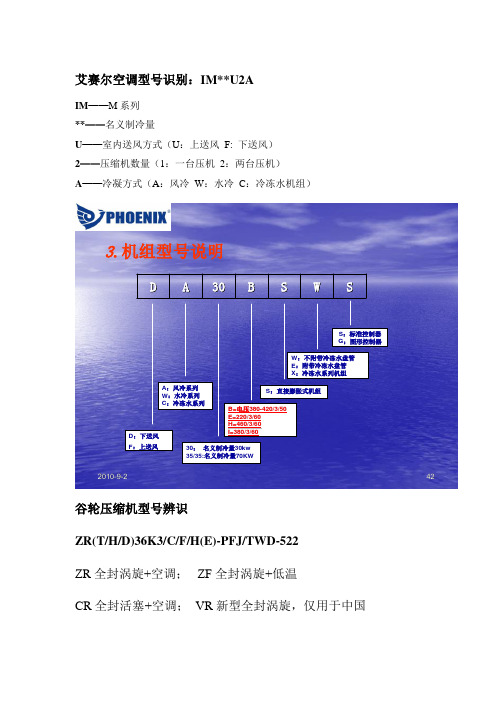
艾赛尔空调型号识别:IM**U2A
IM ——M 系列 **——名义制冷量
U ——室内送风方式(U :上送风 F: 下送风) 2——压缩机数量(1:一台压机 2:两台压机) A ——冷凝方式(A :风冷 W :水冷 C :冷冻水机组)
2010-9-242
3.机组型号说明
S
W
S
B
30
A
D
D :下送风F :上送风
A :风冷系列W :水冷系列C :冷冻水系列
30:名义制冷量30kw 35/35:名义制冷量70KW
B=电压380-420/3/50E=220/3/60H=460/3/60I=380/3/60
S :直接膨胀式机组
W :不附带冷冻水盘管E :附带冷冻水盘管X :冷冻水系列机组
S :标准控制器G :图形控制器
谷轮压缩机型号辨识
ZR(T/H/D)36K3/C/F/H(E)-PFJ/TWD-522 ZR 全封涡旋+空调; ZF 全封涡旋+低温
CR 全封活塞+空调; VR 新型全封涡旋,仅用于中国
T/H/D-并联机组/卧式/数码
36K或12M-制冷量36//12=3HP 120/12=10PH E-可使用新工艺制冷剂,无E只能用R22 PFJ-单相,内置保护,220V/50HZ
TWD-三相,模块保护,380V/50HZ
性能参数
ZR系列压缩机技术参数。
2018 阿特拉斯·科普柯工业动力材料去除工具说明书

工具名称 136备注产品目录使用指南随机附件此指南,为每种工具及其附件(接头、销和防护装置等)提供了详细参数。
操作手册和备用附件清单也包括在内。
可选附件你可在此可找到绝大多数附件的规格参数。
这些规格参数取决于使用工具的具体工位,并且需要单独订阅。
耗气量工具耗气量的单位为升/秒(l/s),与自由空气相关,即:膨胀为大气压力的压缩空气。
除非另有说明,数据为在6.3bar工作压力下的数值,且为最大耗气量。
最大耗气量在工具不配备调速器进行空转(即工具无负荷运转情况)也适用。
配备调速器的工具,在达到最大功率输出时实现最大耗气量。
速度工具速度单位为转数/分(r/min),显示为空转速度,(若无另外规定)即指工具在无负荷和6.3bar工作压力下的运转速度。
最大输出速度为工具无调速器空转速度的50%和配备调速器后空转速度的80%-90%。
订购维修套件在此标题下,列出了针对相关工具进行的最频繁维修工作的维修套件。
振动及噪音排放参照ISO28927的振动值总是作为测定的振动值和偏差给出。
偏差表示测量时的振动范围。
真实工作情况下,使用中工具振动排放范围至少处于同等幅度,通常会非常大。
在众多典型应用操作中使用工具时,大多数情况下,参考ISO28927给出的振动值也可对使用中工具的振动值进行粗略估算。
使用中工具的振动情况会受到非人为可控因素的影响,其中包括维护不当、盗版部件、不平衡的砂轮等。
在测量噪音时,阿特拉斯·科普柯采用了ISO15744标准。
本目录中给出的数值为测得声压等级。
若测得值超出80dB(A),则还会一并提供声功率级。
标准中还描述了如何计算该数值的方法。
不同测试方法和生产过程中数值的偏差为3dB(A)。
使用中工具靠近操作者耳边的噪音值可能与给定值有显著差异,而且在众多应用中,当操作加工声响高于无负载工具噪声时,情况更加突出。
在超出自身控制工作环境下个人风险评估中,因使用公布值,而非实际暴露值所造成的后果,我们阿特拉斯·科普柯公司概不承担责任。
1250W APS X Series 12V DC 230V AC 双口输出电源说明书
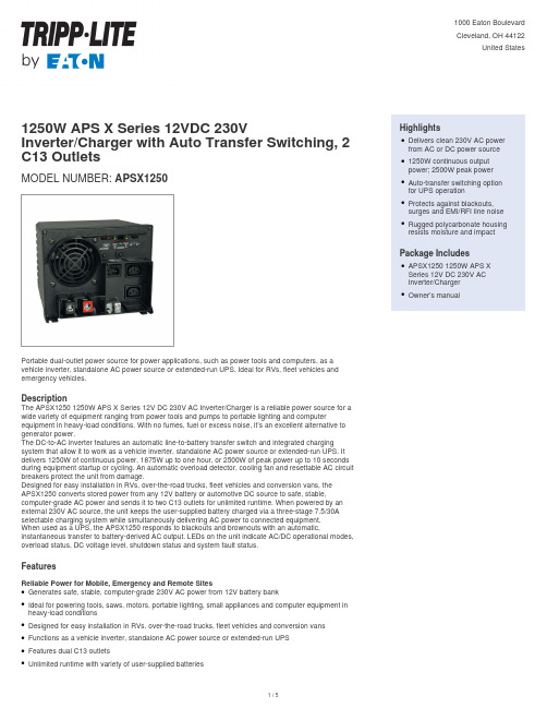
1250W APS X Series 12VDC 230VInverter/Charger with Auto Transfer Switching, 2 C13 OutletsMODEL NUMBER:APSX1250Portable dual-outlet power source for power applications, such as power tools and computers, as a vehicle inverter, standalone AC power source or extended-run UPS. Ideal for RVs, fleet vehicles and emergency vehicles.DescriptionThe APSX1250 1250W APS X Series 12V DC 230V AC Inverter/Charger is a reliable power source for a wide variety of equipment ranging from power tools and pumps to portable lighting and computer equipment in heavy-load conditions. With no fumes, fuel or excess noise, it’s an excellent alternative to generator power.The DC-to-AC inverter features an automatic line-to-battery transfer switch and integrated charging system that allow it to work as a vehicle inverter, standalone AC power source or extended-run UPS. It delivers 1250W of continuous power, 1875W up to one hour, or 2500W of peak power up to 10 seconds during equipment startup or cycling. An automatic overload detector, cooling fan and resettable AC circuit breakers protect the unit from damage.Designed for easy installation in RVs, over-the-road trucks, fleet vehicles and conversion vans, the APSX1250 converts stored power from any 12V battery or automotive DC source to safe, stable, computer-grade AC power and sends it to two C13 outlets for unlimited runtime. When powered by an external 230V AC source, the unit keeps the user-supplied battery charged via a three-stage 7.5/30A selectable charging system while simultaneously delivering AC power to connected equipment.When used as a UPS, the APSX1250 responds to blackouts and brownouts with an automatic, instantaneous transfer to battery-derived AC output. LEDs on the unit indicate AC/DC operational modes, overload status, DC voltage level, shutdown status and system fault status.FeaturesReliable Power for Mobile, Emergency and Remote SitesGenerates safe, stable, computer-grade 230V AC power from 12V battery bankqIdeal for powering tools, saws, motors, portable lighting, small appliances and computer equipment in heavy-load conditionsqDesigned for easy installation in RVs, over-the-road trucks, fleet vehicles and conversion vansqFunctions as a vehicle inverter, standalone AC power source or extended-run UPSqFeatures dual C13 outletsqUnlimited runtime with variety of user-supplied batteriesq HighlightsDelivers clean 230V AC power from AC or DC power source q1250W continuous outputpower; 2500W peak powerqAuto-transfer switching optionfor UPS operationqProtects against blackouts,surges and EMI/RFI line noise qRugged polycarbonate housing resists moisture and impactqPackage IncludesAPSX1250 1250W APS XSeries 12V DC 230V ACInverter/ChargerqOwner’s manualqSpecificationsMeets Normal and Peak Power Demands 1250W of continuous powerq 1875W of reserve power up to 1 hr.q 2500W of peak power up to 10 sec. to accommodate surge power demands during equipment startup and cyclingqAutomatic overload detector, built-in cooling fan and resettable AC circuit breaker protect unit from damageqAutomatic Transfer SwitchingTransfer relay switches to inverter power during blackout in 10 msq 3-position switch enables Auto, Charge Only or System Off mode q DIP switches configure high and low voltage auto-transferq3-Stage 7.5/30A Selectable Battery ChargerServes as battery charger when external 230V AC power is supplied and powering connected equipmentq Protects battery from overcharging and overdischarging q Low-battery protection prevents excessive battery depletion q DIP switches configure wet/gel charging profilesqOptional Remote Control CapabilityRJ45 communication port allows connection of optional remote control module, such as APSRM4q Front-Panel LEDsIndicate AC/DC operational modes, overload status, DC voltage level, shutdown status and system fault statusq Rugged Polycarbonate HousingResists moisture, vibration and impactq Built-in mounting feet for installation on any rigid horizontal surface q Detachable 2 m C13-to-C14 power cord connects to AC power sourceq© 2023 Eaton. All Rights Reserved. Eaton is a registered trademark. All other trademarks are the property of their respective owners.。
中国标准文献分类号CCS

U00/09
船舶综合
U
U10/19
船舶总体
U
U20/29
舾装设备
U
U30/39
船舶专用装备
U
U40/49
船用主辅机
U
U50/59
船舶管路附件
U
U60/69
船舶电气、观通、导航设备
U
U80/89
船舶制造工艺装备
U
U90/99
造船专用工艺设备
U
V00/09
航空、航天综合
V
V10/19
航空、航天材料与工艺
品位、储量及其分析方法分别入各矿产品类。
D80/89
地质勘探设备
D
通用仪器仪表入N91, 凿岩机械入J84, 通用运输、提升机械入J81。
D90/99
矿山机械设备
D
E00/09
石油综合
E
用于生产、流通过程中保证符合文字标准要求的石油产品标样分别入本类各有关类目。
E10/19
石油勘探、开发与集输
E
油气田地面建设、生产设施工程入P类。
F10/19
能源
F
F20/29
电力
F
电站、输配电工程入P类。
F40/49
核材料、核燃料
F
F50/59
同位素与放射源
F
F60/69
核反应堆
F
F70/79
辐射防护与监测
F
F80/89
核仪器与核探测器
F
通用的仪器、仪表入N类。
F90/99
低能加速器
F
G00/09
化工综合
G
造纸入Y30/39, 皮革入Y45/49, 食品发酵、酿造入X60/69, 绝缘漆入K15, 食品添加剂入X40/49, 合成饲料添加剂入B46, 建筑胶粘剂入Q27, 胶鞋入Y78。用于生产、流通过程中保证符合文字标准要求的化工标样分别入本类各有关类目。
- 1、下载文档前请自行甄别文档内容的完整性,平台不提供额外的编辑、内容补充、找答案等附加服务。
- 2、"仅部分预览"的文档,不可在线预览部分如存在完整性等问题,可反馈申请退款(可完整预览的文档不适用该条件!)。
- 3、如文档侵犯您的权益,请联系客服反馈,我们会尽快为您处理(人工客服工作时间:9:00-18:30)。
COP
目前接触到的单片机中都有看门狗模块,不过写过的程序也比较简单,程序能够稳定运行,所以就不怎么理会这看门狗,因此也不知道看门狗是怎么回事。
最近写了个超声波测距的程序,运行过程中程序老是会无故停止,就是死机了。
因此不得不重新面对看门狗,经过两天的奋斗,终于让看门狗顺利工作了。
下面记一下XS128的看门狗的相关寄存器及用法。
看门狗模块用于检测程序的正常运行,启动看门狗后,必须在看门狗复位之前向ARMCOP中依次写入0X55和0XAA ,这样看门狗就会重新启动计时。
如果在规定时间内没有完成向ARMCOP中依次写入0X55和0XAA的操作,就会引起看门狗复位。
这样可以使程序重新运行,减小程序跑死的危害。
看门狗的设置比较简单,只要配置好寄存器COPCTL即可用。
COPCTL的第七位为: WCOP。
若写入COPCTL_WCOP=1,则看门狗行运在窗口模式下,必须在看门狗周期的后25%时间内向ARMCOP依次写入0X55和0XAA。
若在其他时间写入,或写入其他值,都会让看门狗溢出,使单片机复位。
若写入COPCTL_WCOP=0,则看门狗运行在正常模式下。
当看门狗使能后,只要在看门狗溢出周期内依次向ARMCOP写入0X55和0XAA,使看门狗计数复零,即可。
第六位为:RSBCK,BDM模式下的COP和RTI 停止位。
若COPCTL_RSBCK=1,则只要进入BDM模式,就停止COP和RTI(实时中断)计数。
若COPCTL_RSBCK=0,则在BDM模式下允许COP和RTI运行。
低三位为:CR2、CR1、CR0。
这三位是看门狗时钟分频位。
当CR[2:0]=000时,看门狗COP不可用。
只要CR[2:0]不为000,看门狗就开启了。
当CR[2:0]=001时,分频值为(2的14次方)。
当CR[2:0]=010时,分频值为(2的16次方)。
当CR[2:0]=011时,分频值为(2的18次方)。
当CR[2:0]=100时,分频值为(2的20次方)。
当CR[2:0]=101时,分频值为(2的22次方)。
当CR[2:0]=110时,分频值为(2的23次方)。
当CR[2:0]=111时,分频值为(2的24次方)。
看门狗的溢出频率为:COP溢出频率=OSCCLK / CR[2:0]。
OSCCLK为晶振频率。
在正常运行模式下,只要配置好COPCTL,再写好喂狗程序,看门狗COP就可以工作了。
和看门狗COP相关的寄存器还有,不过一般情况下可以不管:
CLKSEL_COPWAI: 当CLKSEL_COPWAI=1时,COP在等待模式下不可用。
当CLKSEL_COPWAI=0时,COP在等待模式下可继续运行。
PLLCTL_PCE: 当PLLCTL_PCE=1时,COP在伪停止模式下可用。
当
PLLCTL_PCE=0时,COP要伪停止模式下不可用。
看门狗的初始化如下:
COPCTL_WCOP=0; //正常COP模式
COPCTL_RSBCK=0; //在BDM模式下允许COP和RTI运行
COPCTL_CR2=1; //CR[2:0]分频值为(2的23次方) COPCTL_CR1=1; //COP溢出周期=OSCCLK/CR[2:0]
COPCTL_CR0=0;
喂狗函数如下:
/////////////////////////////我的喂狗函数
void feeddog()
{
ARMCOP=0X55; //在特定时间内依次向ARMCOP写入0X55,0XAA;
ARMCOP=0XAA;
}。