MA1900机器人使用说明书-印刷版
ICM-1900ID说明书
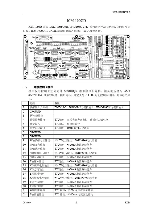
ICM-1900IDICM-1900D是为DMC-18xx/DMC-9940/DMC-21x2系列运动控制卡配套设计的信号接口板。
ICM-1900D与GALIL运动控制器之间通过100芯线缆连接。
一、连接控制卡接口接口板与控制卡之间通过SCSI100pin 槽形接口相连接。
接头的规格为AMP #2-178238-9 或兼容规格。
接口内各引脚定义与GALIL运动控制器相同,具体定义如二、编码器反馈信号接口编码器反馈信号接口接收5V编码器信号,可接收信号规格为TTL或RS422的旋转编码器、光栅尺以及伺服驱动器输出的类编码器信号。
建议采用差分输出的信号形式,并使用屏蔽双绞线传输编码器反馈信号。
如编码器不提供差分驱动,(只提供A、B、Index信号),GALIL也可接收,但此种信号本身极易受到干扰而使系统不能正常工作。
ICM-1900ID上编码器反馈信号接口为9孔D形接头(母),四轴的接口分别标注为:JXE、JYE、JZE、JWE。
在ICM-1900ID内部,对所有输入编码器信号进行了限压保护。
为便于用户连接编码器或光栅尺,在接口内提供了5V电源接口内引脚分配如下:INPUT 5A(6A/7A/8A):GALIL通用输入信号,为TTL电平信号,可选连接光栅尺状态输出信号(部分规格的光栅尺会提供报警信号)。
此引脚为TTL输入,悬空状态下为高电平,输入低电平为有效输入信号。
接口板内采用74LS07(U1)接收此信号。
如不需要从光栅尺/编码器接口接入此信号,请保持此引脚悬空,以避免引入干扰信号。
所有编码器输入采用如下保护电路,以避免由于外部干扰尖峰压导致GALIL控制器内部接收电路损坏。
三、电机放大器/驱动器接口电机放大器/驱动器接口提供用于控制电机放大/驱动器的控制信号,包括用于速度/电流控制的+/-10V 电压信号、用于位置控制的脉冲/方向信号、放大器使能信号以及可选的放大器报警信号。
ICM-1900ID上的电机放大器/驱动器接口为15孔高密度D形接头(母),四轴的接口分别标注为JXD、JYD、JZD、JWD。
(日)安川手册-安川机器人选型手册(全)
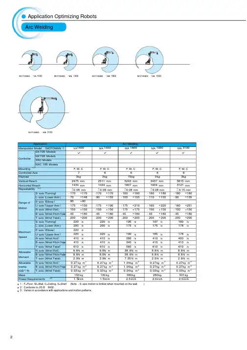
*1: F=Floor, W=Wall, C=Ceiling, S=Shelf (Note : S-axis motion is limited when mounted on the wall.)*2: Conforms to JIS B 8432.*3: Varies in accordance with applications and motion patterns.ApplicationArc Welding Manipulator Model (MOTOMAN -)VA 1400MA 1400MA 1800MA 1900MA 3100ControllerDX 100 Models NX 100 ModelsXRC ModelsNXC 100 Models Mounting *1F , W, C F , W, C F , W, C F , W, C F , W, CControlled Axis 76666Payload3kg3kg 15kg 3kg 3kg Vertical Reach 2475 mm2511 mm 3243 mm 3437 mm 5615 mm Horizontal Reach1434 mm 1434 mm 1807 mm 1904 mm 3121 mm Repeatability *2±0.08 mm±0.08 mm±0.08 mm±0.08 mm±0.15 mmRange ofMotion S -axis (Turning ) -170+170-170+170-180+180-180+180-180+180L -axis (Lower Arm ) -70+148-90+155-100+155-110+155-90+135E -axis (Elbow ) -90+90U -axis (Upper Arm ) -175+150-175+190-175+210-165+220-160+251R -axis (Wrist Roll ) -150+150-150+150-175+175-150+150-150+150B -axis (Wrist Pitch/Yaw) -45+180-45+180-45+180-45+180-45+180T -axis (Wrist Twist ) -200+200-200+200-200+200-200+200-200+200MaximumSpeedS -axis (Turning )220/s 220/s 195/s 197/s 180/s L -axis (Lower Arm )200/s 200/s 175/s 175/s 178/s E -axis (Elbow )220/sU -axis (Upper Arm )220/s 220/s 190/s 185/s 178/s R -axis (Wrist Roll )410/s410/s 380/s 410/s 400/s B -axis (Wrist Pitch/Yaw )410/s410/s 340/s 410/s 410/s T -axis (Wrist Twist )610/s 610/s 560/s 610/s 610/s Allowable MomentR -axis (Wrist Roll)8.8N m8.8N m 38.6N m 8.8N m 8.8N m B -axis (Wrist Pitch/Yaw )8.8N m8.8N m 38.6N m 8.8N m 8.8N m T -axis (Wrist Twist )2.9N m2.9N m 7.35N m 2.9N m 2.9N m Allowable R -axis (Wrist Roll )0.27kg m 20.27kg m 21.04kg m 20.27kg m 20.27kg m 2Inertia B -axis (Wrist Pitch/Yaw)0.27kg m 20.27kg m 21.04kg m 20.27kg m 20.27kg m 2(GD 2/4)T -axis (Wrist Twist )0.03kg m 20.03kg m 20.04kg m 20.03kg m 20.03kg m 2Mass 150kg130kg 380kg 280kg 501kg Power Requirements *31.5kVA1.5kVA2.5kVA2.0kVA2.5kVAApplication Optimizing Robots Arc WeldingMOTOMAN-VA 1400MOTOMAN -MA 3100MOTOMAN-MA 1400MOTOMAN-MA 1800MOTOMAN-MA 1900*1: F=Floor, W=Wall, C=Ceiling, S=Shelf (Note : S -axis motion is limited when mounted on the wall.)*2: Conforms to JIS B 8432.*3: Varies in accordance with applications and motion patterns.*4: When not used with an external cable.ApplicationSpot Welding Manipulator Model (MOTOMAN -)VS 50MS 80MS 120ES 165D ES 165RDES 200D ES 200RD ES 280DControllerDX 100 Models NX 100 ModelsXRC ModelsNXC 100 ModelsMounting *1F F F F S F S FControlled Axis 76666666Payload50kg80kg *4120kg 165kg *4165kg *4200kg *4200kg *4280kg Vertical Reach 2597 mm 3397 mm 2163 mm 3372 mm 4782 mm 3372 mm 4782 mm 3022 mm Horizontal Reach 1630 mm 2061 mm 1623 mm 2651 mm 3140 mm 2651 mm 3140 mm 2446 mmRepeatability *2±0.1 mm±0.07 mm ±0.2 mm ±0.2 mm±0.2 mm 0.2 mm±0.2 mm ±0.2 mm Range ofMotionS -axis (Turning )-180+180-180+180-150+150 -180+180-180+180-180+180-180+180-180+180L -axis (Lower Arm )-60+125-60+120-60+50-60+76-130+80-60+76-130+80-60+76E -axis (Elbow )-170+170U -axis (Upper Arm )-35+215-170+90-105+72 -142.5+230-112+208-142.5+230-107+208-142.5+230R -axis (Wrist Roll )-170+170-360+360*4-360+360-360+360*4-360+360*4 -360+360*4-360+360*4-360+360B -axis (Wrist Pitch/Yaw)-125+125-125+125*4-130+130-130+130*4-130+130*4 -125+125*4-125+125*4-125+125T -axis (Wrist Twist )-180+180-360+360*4-360+360-360+360*4-360+360*4-360+360*4-360+360*4-360+360MaximumSpeedS -axis (Turning )170/s 170/s 130/s 110/s 105/s 95/s 90/s *490/s L -axis (Lower Arm )130/s 140/s110/s 110/s105/s 90/s85/s *480/sE -axis (Elbow )130/sU -axis (Upper Arm )130/s 160/s 130/s 110/s105/s 95/s 85/s *490/s R -axis (Wrist Roll )130/s230/s 215/s 175/s 175/s 120/s 120/s 115/s B -axis (Wrist Pitch/Yaw )130/s230/s 180/s 150/s 150/s 120/s 120/s 110/s T -axis (Wrist Twist )200/s 350/s 300/s 240/s 240/s 190/s 190/s 190/s AllowableMomentR -axis (Wrist Roll )377N m392N m *4588N m 921N m *4921N m *41344N m *41344N m *41333N m B -axis (Wrist Pitch/Yaw )377N m392N m *4588N m 921N m *4921N m *41344N m *41344N m *41333N m T -axis (Wrist Twist )147N m196N m *4392N m 490N m 490N m 715N m 715N m 706N m A ll owab le R -axis (Wrist Roll )29.6kg m 228kg m 2*435kg m 285kg m 2*485kg m 2*4143kg m 2*4143kg m 2*4142kg m 2Inertia B -axis (Wrist Pitch/Yaw)29.6kg m 228kg m 2*435kg m 285kg m 2*485kg m 2*4143kg m 2*4143kg m 2*4142kg m 2(GD 2/4)T -axis (Wrist Twist )12.5kg m 211kg m 2*414.5kg m 245kg m 245kg m 280kg m 280kg m 279kg m 2Mass640kg 550kg 950kg 1100kg 1540kg 1130kg 1570kg 1120kg Power Requirements *35.0kVA 4.0kVA 4.5kVA 5.0kVA5.0kVA5.0kVA 5.0kVA 10kVAMOTOMAN -VS 50MOTOMAN -MS 80MOTOMAN -MS 120MOTOMAN -ES 165DMOTOMAN-ES 200DMOTOMAN-ES 200RDMOTOMAN-ES 280DMOTOMAN-ES 165RDApplication Optimizing Robots Spot WeldingApplicationMaterial Handling(General purpose)Manipulator Model (MOTOMAN -)HP 3JMH 5MH 5LMH 6MH 6SHP 20DHP 20D -6MH 50MH 50-20ControllerDX 100 ModelsNX 100 Models XRC Models NXC 100 Models*4*4Mounting *1F, W, CF , W, CF , W, CF , W, CF , W, CF, W, CF, W, CF , W, CF , W, CControlled Axis 666666666Payload 3kg 5kg 5kg 6kg 6kg 20kg 6kg 50kg 20kg Vertical Reach 804 mm 1193 mm 1560 mm 2486 mm 1597 mm 3063 mm 3459 mm 3578 mm 5585 mm Horizontal Reach 532 mm706 mm895 mm1422 mm997 mm1717 mm1915 mm2061 mm3106 mmRepeatability *2±0.03 mm ±0.02 mm ±0.03 mm ±0.08 mm ±0.08 mm ±0.06 mm ±0.06 mm ±0.07 mm ±0.15 mmRange of MotionS -axis (Turning )-160+160 -170+170 -170+170 -170+170 -170+170 -180+180 -180+180 -180+180 -180+180L -axis (Lower Arm) -85+90-65+150-65+150 -90+155 -80+133-110+155 -110+155-90+135 -90+135U -axis (Upper Arm) -105+260 -136+255 -138+255 -175+250 -130+165 -165+255 -160+255 -170+251 -160+251R -axis (Wrist Roll ) -170+170 -190+190 -190+190 -180+180 -180+180 -200+200 -200+200 -360+360 -190+190B -axis (Wrist Pitch/Yaw ) -120+120 -125+125 -125+125 -45+225 -45+225-50+230-50+230 -125+125-50+230T -axis (Wrist Twist) -360+360 -360+360 -360+360 -360+360 -360+360 -360+360 -360+360 -360+360 -360+360Maximum SpeedS -axis (Turning )200/s 376/s 270/s 220/s 220/s 197/s 197/s 180/s 180/s L -axis (Lower Arm )150/s350/s 280/s 200/s 220/s 175/s 175/s 178/s 178/s U -axis (Upper Arm )190/s 400/s 300/s 220/s 220/s 187/s 187/s 178/s 178/s R -axis (Wrist Roll )300/s 450/s 450/s 410/s 410/s 400/s 400/s 250/s 400/s B -axis (Wrist Pitch/Yaw )300/s 450/s 450/s 410/s 410/s 400/s 400/s 250/s 400/s T -axis (Wrist Twist)420/s 720/s 720/s 610/s 610/s 600/s 600/s 360/s 600/s Allowable Moment R -axis (Wrist Roll )5.39N m 12N m 12N m 11.8N m 11.8N m 39.2N m 11.8N m 216N m 39.2N m B -axis (Wrist Pitch/Yaw)5.39N m 12N m 12N m 9.8N m 9.8N m 39.2N m 9.8N m 216N m 39.2N m T -axis (Wrist Twist )2.94N m 7N m7N m5.9N m5.9N m19.6N m5.9N m147N m 19.6N m Allowable Inertia (GD 2/4)R -axis (Wrist Roll )0.1kg m 20.30kg m 20.30kg m 20.27kg m 20.27kg m 21.05kg m 20.24kg m 228kg m 21.05kg m 2B -axis (Wrist Pitch/Yaw)0.1kg m 20.30kg m 20.30kg m 20.27kg m 20.27kg m 21.05kg m 20.17kg m 228kg m 21.05kg m 2T -axis (Wrist Twist)0.03kg m 20.1kg m 20.1kg m 20.06kg m 20.06kg m 20.75kg m 20.06kg m 211kg m 20.75kg m 2Mass27kg28kg 30kg 130kg 120kg 268kg 273kg 550kg 495kg Power Requirements*30.5kVA1.0kVA1.0kVA1.5kVA1.5kVA2.0kVA2.0kVA4.0kVA3.5kVA*1: F=Floor, W=Wall, C=Ceiling, S=Shelf (Note : S-axis motion is limited when mounted on the wall.)*2: Conforms to JIS B 8432.*3: Varies in accordance with applications and motion patterns.*4: Only for handling.HandlingApplication Optimizing Robots MOTOMAN -HP 3J MOTOMAN-HP 20DMOTOMAN-HP 20D -6MOTOMAN-MH 50MOTOMAN-MH 50-20MOTOMAN-MH 5MOTOMAN-MH 5LMOTOMAN-MH 6MOTOMAN-MH 6SApplicationMaterial Handling(General purpose)Manipulator Model (MOTOMAN -)MH 80MH 165MH 200MH 215MH 250UP 350DUP 400RDUP 350D -500UP 350D -600ControllerDX 100 ModelsNX 100 Models XRC Models NXC 100 ModelsMounting *1F F F F F F S F FControlled Axis 666666666Payload 80kg 165kg *4200kg *4215kg 250kg 350kg 400kg 500kg 600kg Vertical Reach 3578 mm 3372 mm 3372 mm 3894 mm 3490 mm 2761 mm 4908 mm 2761 mm 2761 mm Horizontal Reach 2061 mm2651 mm2651 mm2912 mm2710 mm2542 mm3518 mm2542 mm2542 mmRepeatability *2±0.07 mm ±0.2 mm 0.2 mm ±0.2 mm 0.2 mm ±0.5 mm ±0.5 mm ±0.5 mm ±0.5 mmRange of Motion S -axis (Turning )-180+180 -180+180-180+180 -180+180 -180+180 -150+150 -150+150 -150+150 -150+150L -axis (Lower Arm)-90+135-60+76-60+76-60+76-60+76-55+61-122+20-55+61-55+61U -axis (Upper Arm ) -170+251 -142.5+230 -142.5+230 -142.5+230 -142.5+230-113+30-9+120-113+30-113+30R -axis (Wrist Roll ) -360+360 -360+360*4 -360+360*4 -360+360 -360+360 -360+360 -360+360 -360+360 -360+360B -axis (Wrist Pitch/Yaw ) -125+125 -130+130*4 -125+125*4 -125+125 -125+125 -125+125 -120+120 -125+125 -125+125T -axis (Wrist Twist ) -360+360 -360+360*4 -360+360*4 -360+360 -360+360 -360+360 -360+360 -360+360 -360+360Maximum SpeedS -axis (Turning )170/s 110/s 95/s 100/s 100/s 95/s 80/s 80/s 60/s L -axis (Lower Arm)140/s 110/s 90/s 90/s 90/s 95/s 80/s 80/s 70/s U -axis (Upper Arm )160/s 110/s 95/s 97/s 97/s 95/s 80/s 80/s 70/s R -axis (Wrist Roll )230/s 175/s 120/s 120/s 120/s 100/s 80/s 100/s 80/s B -axis (Wrist Pitch/Yaw )230/s 150/s120/s 120/s 120/s 100/s 80/s 100/s 80/s T -axis (Wrist Twist)350/s 240/s190/s190/s190/s 160/s 160/s 160/s 160/s Allowable Moment R -axis (Wrist Roll )392N m 921N m *41344N m *41176N m 1385N m 1960N m 1960N m 1960N m 2450N m B -axis (Wrist Pitch/Yaw)392N m 921N m *41344N m *41176N m 1385N m 1960N m 1960N m 1960N m 2450N m T -axis (Wrist Twist )196N m 490N m 715N m 710N m735N m 823N m 833N m 823N m 823N m Allowable Inertia (GD 2/4)R -axis (Wrist Roll )28kg m 285kg m 2*4143kg m 2*4317kg m 2317kg m 2150kg m 2150kg m 2150kg m 2200kg m 2B -axis (Wrist Pitch/Yaw)28kg m 285kg m 2*4143kg m 2*4317kg m 2317kg m 2150kg m 2150kg m 2150kg m 2200kg m 2T -axis (Wrist Twist)11kg m 245kg m 280kg m 2200kg m 2200kg m 290kg m 250kg m 290kg m 290kg m 2Mass555kg 1100kg 1130kg 1140kg 1130kg 2200kg 3600kg 2350kg 2400kg Power Requirements *34.5kVA5.0kVA5.0kVA6.0kVA6.0kVA5.5kVA12kVA5.5kVA7.0kVA*1: F=Floor, W=Wall, C=Ceiling, S=Shelf (Note : S-axis motion is limited when mounted on the wall.)*2: Conforms to JIS B 8432.*3: Varies in accordance with applications and motion patterns.*4: When not used with an external cable.MOTOMAN-MH 80MOTOMAN -MH 250MOTOMAN -UP 350D MOTOMAN -UP 400RDMOTOMAN -UP 350D -500MOTOMAN -UP 350D -600MOTOMAN-MH 165MOTOMAN-MH 200MOTOMAN-MH 215ApplicationPicking / Packing PalletizingManipulator Model(MOTOMAN -)MPK 2MPK 50MPL 80MPL 100MPL 160MPL 300MPL 500MPL 800ControllerDX 100 Models NX 100 ModelsXRC Models NXC 100 ModelsMounting *1F ,W,C F F F F F F FControlled Axis 54544444Payload2kg50kg 80kg 100kg 160kg 300kg 500kg 800kg Vertical Reach 1625 mm 1668 mm 3291 mm 3024 mm 3024 mm 3024 mm 3024 mm 3024 mm Horizontal Reach900 mm1893 mm 2061 mm 3159 mm 3159 mm 3159 mm 3159 mm 3159 mm Repeatability *2±0.5 mm±0.5 mm ±0.07 mm ±0.5 mm ±0.5 mm ±0.5 mm ±0.5 mm ±0.5 mm Range of MotionS -axis (Turning )-170+170-180+180-180+180-180+180 -180+180 -180+180 -180+180 -180+180L -axis (Lower Arm)-120+120-35+80-90+135-45+90-45+90-45+90-45+90-45+90U -axis (Upper Arm)-102+282-105+15-160+35-120+15.5-120+15.5-120+15.5-120+15.5-120+15.5R -axis (Wrist Roll )B -axis (Wrist Pitch/Yaw)-150+150 -15+15T -axis (Wrist Twist)-270+270 -350+350- 360+360-360+360 -360+360-360+360-360+360-360+360Maximum SpeedS -axis (Turning )320/s185/s 170/s 140/s 140/s 90/s85/s 65/s L -axis (Lower Arm )330/s215/s 170/s 140/s 140/s 100/s 85/s 65/s U -axis (Upper Arm )330/s215/s 170/s140/s 140/s110/s 85/s 65/sR -axis (Wrist Roll )B -axis (Wrist Pitch/Yaw )380/s 170/s T -axis (Wrist Twist )2000/s374/s350/s 305/s 305/s 195/s 195/s 125/sAllowableMoment R -axis (Wrist Roll )B -axis (Wrist Pitch/Yaw)3.5N m 78.4N m T -axis (Wrist Twist )1.5N m 20.5N m Allowable R -axis (Wrist Roll )Inertia B -axis (Wrist Pitch/Yaw)0.065kg m 216kg m 2(GD 2/4)T -axis (Wrist Twist)0.012kg m 25.5kg m 26.1kg m 280kg m 280kg m 2140kg m 2200kg m 2550kg m 2Mass75kg 670kg 550kg 1700kg 1700kg 1820kg 2300kg 2550kg Power Requirements *31.5kVA4.0kVA 4.0kVA9.5kVA9.5kVA 9.5kVA 9.5kVA 10kVA*1: F=Floor, W=Wall, C=Ceiling, S=Shelf (Note : S -axis motion is limited when mounted on the wall.)*2: Conforms to JIS B 8432.*3: Varies in accordance with applications and motion patterns.Picking / PackingPalletizingApplication Optimizing Robots MOTOMAN -MPK 2MOTOMAN -MPK 50MOTOMAN-MPL 80MOTOMAN -MPL 160MOTOMAN -MPL 300MOTOMAN -MPL 500MOTOMAN -MPL 800MOTOMAN-MPL 100ApplicationAssembly & Distributing Manipulator Model(MOTOMAN -)SIA 5D SIA 10D SIA 20DSIA 30D SIA 50DSDA 5D SDA 10D SDA 20DControllerDX 100 Models NX 100 ModelsXRC ModelsNXC 100 ModelsMounting *1F , W, C F, W, C F , W, C F F F , C F FDegrees of Freedom 77777151515Payload5kg 10kg 20kg 30kg 50kg 5kg/Arm 10kg/Arm 20kg/Arm Vertical Reach 1007 mm 1203 mm 1498 mm 2597 mm 2597 mm 1118 mm 1440 mm 1820 mm Horizontal Reach 559 mm 720 mm 910 mm 1485 mm 1630 mm 1604 mm 1970 mm 2590 mm Ripeatability*2±0.06 mm±0.1 mm±0.1 mm±0.1 mm±0.1 mm±0.06 mm ±0.1 mm ±0.1 mm Range of MotionRotation-170+170 -170+170 -180+180S -axis (Turning ) -180+180 -180+180-180+180 -180+180 -180+180 -90+270, -270+90 -180+180 -180+180L -axis (Lower Arm) -110+110 -110+110 -110+110 -125+125 -60+125 -110+110 -110+110 -110+110E -axis (Elbow ) -170+170 -170+170 -170+170 -170+170 -170+170 -170+170-170+170 -170+170U -axis (Upper Arm ) -90+115 -135+135 -130+130 -110+110 -35+215-90+115 -135+135 -130+130R -axis (Wrist Roll ) -180+180 -180+180 -180+180 -170+170 -170+170 -180+180 -180+180 -180+180B -axis (W rist Pitch/Yaw ) -110+110 -110+110 -110+110 -110+110 -125+125 -110+110 -110+110 -110+110T -axis (Wrist Twist) -180+180-180+180 -180+180 -180+180 -180+180-180+180 -180+180 -180+180Maximum SpeedRotation180/s 130/s 125/s S -axis (Turning )200/s 170/s130/s 130/s 170/s 200/s 170/s 130/s L -axis (Lower Arm )200/s170/s 130/s 130/s 130/s 200/s 170/s 130/s E -axis (Elbow )200/s170/s 170/s 130/s 130/s 200/s 170/s 170/s U -axis (Upper Arm )200/s 170/s 170/s 130/s 130/s 200/s 170/s 170/s R -axis (Wrist Roll )200/s 200/s 200/s 170/s 130/s 200/s 200/s 200/s B -axis (W rist Pitch/Yaw )230/s 200/s 200/s 170/s 130/s 230/s 200/s 200/s T -axis (Wrist Twist )350/s400/s 400/s 200/s 200/s 350/s 400/s 400/s AllowableMoment R -axis (Wrist Roll )14.7N m31.4N m 58.8N m 117.6N m 377N m 14.7N m 31.4N m 58.8N m B -axis (W rist Pitch/Yaw)14.7N m 31.4N m 58.8N m 117.6N m 377N m 14.7N m 31.4N m 58.8N m T -axis (Wrist Twist )7.35N m 19.6N m 29.4N m 58.8N m 147N m 7.35N m 19.6N m 29.4N m Allowable R -axis (Wrist Roll )0.45kg m 21.0kg m 24.0kg m 26.0kg m 229.6kg m 20.45kg m 21.0kg m 24.0kg m 2Inertia B -axis (W rist Pitch/Yaw)0.45kg m 21.0kg m 24.0kg m 26.0kg m 229.6kg m 20.45kg m 21.0kg m 24.0kg m 2(GD 2/4)T -axis (Wrist Twist )0.11kg m 20.4kg m 22.0kg m 23.0kg m 212.5kg m 20.11kg m 20.4kg m 22.0kg m 2Mass 30kg 60kg 120kg 345kg 640kg 110kg 220kg 380kg Power Requirements *31.0kVA1.5kVA2.2kVA 2.8kVA 5.0kVA1.4kVA2.7kVA4.4kVA*1: F=Floor, W=Wall, C=Ceiling, S=Shelf *2: Conforms to JIS B 8432.*3: Varies in accordance with applications and motion patterns.MOTOMAN-SIA 5DMOTOMAN-SIA 50DMOTOMAN-SDA 5DMOTOMAN-SDA 10DMOTOMAN-SDA 20DMOTOMAN-SIA 10DMOTOMAN-SIA 20DMOTOMAN-SIA 30DAssembly & DistributingApplication Optimizing RobotsApplicationPress Handling Manipulator Model (MOTOMAN -)EPH 130EPH 130REPH 130RLEPH 4000EP 4000NControllerDX 100 Models NX 100 ModelsXRC ModelsNXC 100 ModelsMounting *1F S S S SControlled Axis 66666Payload130kg 130kg 130kg 200kg 200kg Vertical Reach 3372 mm 3775 mm 4151 mm 2629 mm 2629 mm Horizontal Reach2651 mm3134 mm 3474 mm 3505 mm 3505 mm Repeatability *2±0.2 mm±0.2 mm ±0.3 mm ±0.5 mm ±0.5 mm Range of MotionS -axis (Turning ) -180+180 -180+180 -180+180 -150+150 -150+150L -axis (Lower Arm ) -60+76-130+70-130+70-122+25-122+25U -axis (Upper Arm ) -137.5+230-70+95-70+95-70+53-70+53R -axis (Wrist Roll ) -360+360 -360+360 -360+360 -360+360 -360+360B -axis (Wrist Pitch/Yaw) -130+130 -130+130 -130+130 -120+120 -120+120T -axis (Wrist Twist ) -360+360 -360+360 -360+360 -360+360-360+360Maximum SpeedS -axis (Turning )130/s 110/s 110/s 90/s 90/s L -axis (Lower Arm )130/s110/s 110/s 90/s 90/s U -axis (Upper Arm )130/s110/s 110/s 90/s 90/s R -axis (Wrist Roll )215/s 215/s 215/s 80/s 80/s B -axis (Wrist Pitch/Yaw )180/s180/s 180/s 80/s 80/s T -axis (Wrist Twist )300/s 300/s 300/s 160/s 160/s AllowableMomentR -axis (Wrist Roll )735N m735N m 735N m 1274N m 1274N m B -axis (Wrist Pitch/Yaw)735N m 735N m 735N m 2156N m 2156N m T -axis (Wrist Twist )421N m421N m 421N m 0N m 0N m Allowabl e R -axis (Wrist Roll )45kg m 245kg m 245-130kg m 2*484.5kg m 284.5kg m 2Inertia B -axis (Wrist Pitch/Yaw )45kg m 245kg m 245-130kg m 2*4330kg m 2330kg m 2(GD 2/4)T -axis (Wrist Twist )15kg m 215kg m 215-38kg m 2*480kg m 280kg m 2Mass 1495kg 1420kg 1445kg 3050kg 3100kg Power Requirements *310kVA 10kVA 10kVA 22kVA22kVA*1:F=Floor, W=Wall, C=Ceiling, S=Shelf (Note : S -axis motion is limited when mounted on the wall.)*2: Conforms to JIS B 84323.*3: Varies in accordance with applications and motion patterns.*4: Varies in accordance with load torque.Press HandlingApplication Optimizing Robots MOTOMAN-EPH 130MOTOMAN-EP 4000NMOTOMAN-EPH 130RMOTOMAN-EPH 130RLMOTOMAN-EPH 4000*1: F=Floor, W=Wall, C=Ceiling, S=Shelf (Note : S -axis motion is limited when mounted on the wall.)*2: Conforms to JIS B 8432.*3: Varies in accordance with applications and motion patterns.*4-130+90(S-axis -90+90)-130+30(S-axis +90+120)-130+30(S-axis -90-120)ApplicationPainting Manipulator Model (MOTOMAN -)EPX 1250EPX 2050PX 2750EPX 2700EPX 2800EPX 2800R EPX 2900ControllerDX 100 Models NX 100 ModelsXRC ModelsNXC 100 ModelsMounting *1F ,W,C F F W F S FControlled Axis 6666666Payload5kg 15kg 10kg 15kg 20kg 15kg 20kg Vertical Reach 1852 mm 2806 mm 3758 mm 5147 mm 4582 mm 4751 mm 4410 mm Horizontal Reach1256 mm 2054 mm 2729 mm 2700 mm 2778 mm 2825 mm 2900 mm Repeatability *2±0.15 mm±0.5 mm±0.5 mm±0.15 mm ±0.5 mm ±0.5 mm ±0.5 mm Range of MotionS -axis (Turning ) -170+170 -90+90 -150+150-125+25, -25+125 -150+150-120+120 -150+150L -axis (Lower Arm )-65+120 -50+100-40+90-65+140-45+120*4-50+110U -axis (Upper Arm )-165+205-163+5+10+168-65+90-85+90-70+90-70+90R -axis (Wrist Roll ) -190+190 -360+360 -260+260 -720+720-360+360 -360+360 -360+360B -axis (Wrist Pitch/Yaw) -145+145 -360+360 -270+270 -720+720-360+360 -360+360 -360+360T -axis (Wrist Twist ) -360+360 -360+360 -260+260 -720+720-360+360-360+360-360+360Maximum SpeedS -axis (Turning )185/s 2.0m/s 2.0m/s 2.0m/s 2.0m/s 2.0m/s155/s L -axis (Lower Arm )185/s 125/s U -axis (Upper Arm )185/s 155/s R -axis (Wrist Roll )360/s 450/s B -axis (Wrist Pitch/Yaw )410/s 550/s T -axis (Wrist Twist )500/s 650/s Allowable MomentR -axis (Wrist Roll )8.0N m 45.8N m 30.4N m 45.8N m 77.4N m 45.8N m 72.0N m B -axis (Wrist Pitch/Yaw)8.0N m 33.8N m 19.6N m 33.8N m 49.9N m 33.8N m 51.5N m T -axis (Wrist Twist )3.0N m 10.8N m 9.8N m 10.8N m 19.6N m 10.8N m 19.6N m Allowable R -axis (Wrist Roll )0.20kg m 21.45kg m 20.97kg m 21.45kg m 22.45kg m 21.45kg m 22.73kg m 2Inertia B -axis (Wrist Pitch/Yaw)0.20kg m 20.79kg m 20.40kg m 20.79kg m 21.20kg m 20.79kg m 21.63kg m 2(GD 2/4)T -axis (Wrist Twist )0.07kg m 20.10kg m 20.10kg m 20.10kg m 20.20kg m 20.10kg m 20.20kg m 2Mass110kg 540kg 560kg 590kg 650kg 820kg 1030kg Power Requirements*31.5kVA5.0kVA 5.0kVA 5.0kVA5.0kVA 5.0kVA5.0kVAType L Type RMOTOMAN -EPX 1250MOTOMAN -EPX 2800MOTOMAN -EPX 2800R MOTOMAN -EPX 2900MOTOMAN -EPX 2050MOTOMAN -PX 2750MOTOMAN -EPX 2700PaintingApplication Optimizing RobotsControllersController ModelDX 100DX 100(Assembly & Distributing )NX 100NXC 100Manipulator Model Small Model VA 1400, MA 1400, MA 1900MA 3100, MH 5, MH 5L, MH 6, MH 6S, HP 20D, HP 20D -6, MPK 2SIA 5D, SIA 10D, SIA 20DHP 3J, MH 5, MH 5LLarge Model MA 1800, VS 50, MS 80, MS 120, ES 165D, ES 165RD, ES 200D,ES 200RD, ES 280D *2, MH 50, MH 50-20, MH 80, MH 165, MH 200,MH 215*2,MH 250*2, UP 350D, UP 400RD, UP 350D -500, UP 350D -600, MPK 50*2, MPL 80*2, MPL 100*2, MPL 160*2, MPL 300*2, MPL 500*2, SIA 30D, SIA 50DSDA 5D, SDA 10D, SDA 20D EPH 130, EPH 130R,EPH 130RL, EPH 4000,EP 4000N Dimensions(W ×H ×D )Small Model425×1200×450 mm (Possible to control 3 external axes )500×580×580 mm (Possible to control 1 external axes )500×1200×500mm (Possible to control 2 external axes )485×183×300 mm (Possible to control 1 external axes )Large Model425×1200×450 mm (Possible to control 2 external axes )500×880×580 mm (Possible to control 1 external axes )600×1200×550 mm(Possible to control 2 external axes)Approximate Mass Small Model100kg 100kg 100kg 16kg Large Model 100kg *2150kg 150kg IEC Protection Class IP 54IP 54IP 51IP 20Dimensions (W ×H ×D )169×314.5×50 mm 169×314.5×50 mm 199×338×60 mm 199×338×60 mm Approximate Mass 0.990kg 0.990kg 1.320kg 1.320kg IEC Protection Class IP 65IP 65IP 65IP 65External Interface CF slot ×1USB Port (1.1)×1CF slot ×1USB Port (1.1)×1CF slot ×1CF slot ×1Number of Controlled Manipulators Up to 8 manipulators Up to 8 manipulators Up to 4 manipulators Up to 4 manipulators Number of Controlled Axes Up to 72 axes Up to 72 axes Up to 36 axes Up to 36 axesNumber ofJOBs Robot 16 JOBs 16 JOBs 8 JOBs 8 JOBs System 4 JOBs 4 JOBs 4 JOBs 4 JOBs Up to 32 groups Up to 32 groups Up to 16 groups Up to 16 groups Robot Up to 8 groups (R 1 to R 8)Up to 8 groups (R 1 to R 8)Up to 4 groups (R 1 to R 4)Up to 4 groups (R 1 to R 4)Base Up to 8 groups (B 1 to B 8)Up to 8 groups (B 1 to B 8)Up to 4 groups (B 1 to B 4)Up to 4 groups (B 1 to B 4)Station Up to 24 groups (S 1 to S 24)Up to 24 groups (S 1 to S 24)Up to 12 groups (S 1 to S 12)Up to 12 groups (S 1 to S 12)JOB CapacityJOB :200000 steps Robot command :10000 steps JOB :200000 steps Robot command :10000 steps JOB :60000 steps Robot command :10000 steps JOB :60000 stepsRobot command :10000 stepsCIO Ladder 20000 steps 20000 stepsStandard :10000 steps Extension :15000 steps Standard :10000 stepsExtension :15000 stepsI/OSystem Input :2048(max.)System Output :2048(max.)System Input :2048(max.)System Output :2048(max.)System Input :1024(max.)System Output :1024(max.)System Input :1024(max.)System Output :1024(max.)Number of JOB NamesUp to 32 digitsUp to 32 digitsUp to 8 digitsUp to 8 digits*1: These specifications and dimensions are for standard specifications and they are subject to change due to the optional installation.*2: When manipulator is ES 280D, MH 215, MH 250, MPK 50, MPL 80, MPL 100, MPL 160, MPL 300, and MPL 500, the regenerative resistor box (120 mm in depth, 50kg ) is mounted on the surface of the backside of the controller. Note : Contact YASKAWA regarding the dimension of the controller for MPL 800.Standard Specifi cations of Controller*1Small modelSmall model(for single -arm robots )Small modelLarge modelLarge model (for dual -arm robots)Large model DX 100NXC 100DX 100(Assembly & Distributing)NX 100Co n t r o l l e rs Pr o g r a m m i n g Pe n d a n t So f t w a r e Number of Controlled GroupsController Model NX 100(Painting )XRC (Painting )ManipulatorModel Standard Pendant EPX 2050, EPX 2700, EPX 2800, EPX 2800R, EPX 2900PX 2750Explosion-proof PendantEPX 2050, EPX 2700, EPX 2800, EPX 2800R, EPX 2900PX 2750Dimensions(W ×H ×D )Standard Pendant974×1200×600 mm(Possible to control 3 external axes )974×900×600 mm(Possible to control 3 external axes)Explosion-proof Pendant 974×1200×600 mm(Possible to control 3 external axes )974×1300×600 mm(Possible to control 3 external axes)Approximate Mass Standard Pendant 250kg 100kg Explosion -proof Pendant 250kg 200kg IEC Protection Class IP 41(Option : IP 54)IP 41Dimensions (W ×H ×D )Standard Pendant 199×338×60 mm 200×325×77 mm Explosion -proof Pendant 235×203×78 mm211×382×75 mmApproximate MassStandard Pendant1.32kg 1.2kgExplosion-proof Pendant 1.25kg 2.0kg IEC Protection Class IP 65IP 40External InterfaceCF slot ×1Standard RS 232C for Backup Explosion -proof N/ANumber of Controlled Manipulators Up to 4 robots Up to 3 robots Number of Controlled Axes Up to 36 axesUp to 27 axesNumber of JOBs Robot 8 JOBs 6 JOBsSystem4 JOBsUp to 16 groupsUp to 8 groupsRobot UP to 4 groups (R 1 to R 4)UP to 3 groups (R 1 to R 3)Base UP to 4 groups (B 1 to B 4)UP to 3 groups (B 1 to B 3)StationUP to 12 groups (S 1 to S 12)UP to 6 groups (S 1 to S6)JOB Capacity 60000 steps 10000 steps60000 steps 10000 steps CIO Ladder Standard :10000 steps Extension :15000 steps 1500 stepsI/OSystem Input :1024(max.)System Output :1024(max.)System Input :256(max.)System Output :256(max.)Number of JOB NamesUp to 8 digitsUp to 8 digits*: These specifications and dimensions are for standard specifications and they are subject to change due to the optional installation.Note : Contact YASKAWA regarding the dimension of the controller for EPX1250.Standard Specifi cations of Controller *Standard pendant model Standard pendant modelExplosion -proof pendant model Explosin -proof pendant modelNX 100(Painting )XRC (Painting )For PaintingCo n t r o l l e r s So f t w a r e Pr o g r a m m i n g Pe n d a n t Number of Controlled Groups。
安川机器人选型手册(全)

6 3 kg 2511 mm 1434 mm ±0. 08 mm + 170 - 170 + 155 - 90
- 175 - 150 - 45 - 200
6 15 kg 3243 mm 1807 mm ±0.08 mm + 180 - 180 + 155 - 100
- 175 - 175 - 45 - 200
6 6 4 200 kg * 200 kg * 280 kg 3372 mm 4782 mm 3022 mm 2651 mm 3140 mm 2446 mm ±0. 2 mm ±0 .2 mm 0.2 mm +180 - 180 +180 -180 +180 -180 +76 -60 + 76 -130 +80 -60 -107 - 360 - 125 - 360 90 85 +208 +360 *4 +125*4 +360*4 /s * 4 /s * 4 -142 .5 - 360 - 125 - 360 90 80 +230 +360 +125 +360
6
6 6 4 165 kg * 165 kg * 4 3372 mm 4782 mm 2651 mm 3140 mm ± ±0 .2 mm 0 .2 mm -180 +180 - 180 +180 +76 -60 -130 +80
-142 .5 +230 -360 +360*4 -130 +130*4 -360 +360*4 110 /s 110 /s
110 /s 175 /s 150 /s 240 /s 921 N m * 4 921 N m * 4 490 N m 85kg m 2 * 4 85kg m 2 * 4 45 kg m 2 1100 kg 5. 0kVA
LG L1900J 用户指南(电子版)说明书
dealer when you require service.
Important Precautions
This unit has been engineered and manufactured to ensure your personal safety, however improper use may result in potential electrical shock or fire hazards. In order to allow the proper operation of all safeguards incorporated in this display, observe the following basic rules for its installation, use, and servicing.
On Safety
Use only the power cord supplied with the unit. In case you use another power cord, make sure that it is certified by the applicable national standards if not being provided by the supplier. If the power cable is faulty in any way, please contact the manufacturer or the nearest authorized repair service provider for a replacement.
科姆龙1900说明书-变频器的安装配线
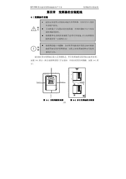
第四章第四章 变频器的安装配线变频器的安装配线变频器的安装配线4.1变频器的安装变频器的安装-16--17-②变频器的安装尺寸表(如下表4-1所示)-18--19-表4-1变频器安装尺寸表变频器安装尺寸表变频器型号变频器型号 G :恒转矩负载恒转矩负载 P :风机水泵负载风机水泵负载A (㎜)B (㎜) L (㎜) L1L1 (㎜) W (㎜)H (㎜)安装安装 孔径(㎜)外形外形 图号图号 毛重(kg )KV1900-G0007C-4T KV1900-G0015C-4T KV1900-G0022C-4T KV1900-G0004C-2S KV1900-G0007C-2S KV1900-G0015C-2S KV1900-G0004C-2T KV1900-G0007C-2T 108 175 1481561181855.5图4-5 2.5KV1900-G0037C-4T KV1900-G0055C-4T KV1900-P0055C-4T KV1900-G0022C-2S KV1900-G0015C-2T KV1900-G0022C-2T140 222 1541651502325.5图4-544.3变频器的配线变频器的配线 4.3.1注意事项注意事项::-20--21-4.3.2变频器端子说明及配线变频器端子说明及配线1、 主回路端子功能说明(见下表4-2)表4-2主回路端子功能说明主回路端子功能说明2、 主回路端子:端子R 、S 、T 及L 1、L 2接线示意图R S T 三相交流电源L1L2单相交流电源(单相单相220220220VA C VA C))(三相三相380380380//220220VAC VAC VAC))-22-3、 主回路端子:端子U 、V、W 及P+、DB 接线示意图P+DBU V W交流电动机制动电阻4、 主回路端子:端子G接线示意图G5、控制回路端子示意图图4-10控制回路端子控制回路端子功能说明见下表-23--24-表4-3控制回路端子功能说明控制回路端子功能说明类别 端子端子 标号标号 功能说明功能说明电气规格电气规格 内部电路内部电路FWDFWD-COM 之间短接时正转,开路时减速并停止 运行控制端子 RE V RE V -COM 之间短接时反转,开路时减速并停止 INPUT ,0~24V 电平信号,低电平有效,1m A X 1 X 2 X3 多功能输入端子X 4Xn (n=1,2,3,4)-COM 之间短接时有效,其功能分别由参数F 051~F 054设定INPUT ,0~24V 电平信号,低电平有效,1m AY 1多功能可编程集电极开路输出1,可编程定义为多种功能的开关量输出端子,参考地为COM OUTPUT ,最大负载电流I≤50m AV模拟电压信号输入1路,参考地为GNDINPUT ,0~10V 直流电压输入输出端子I模拟电流信号输入1路,参考地为GNDINPUT ,0~20m A (4~20m A)直流电流-25-类别 端子端子 标号标号 功能说明功能说明 电气规格电气规格 内部电路内部电路AM多功能可编程模拟电压输出,参考地为GNDOUTPUT ,0~10V 直流电压 输入输出端子FM多功能可编程频率输出,参考地为GND OUTPUT ,0~20kHz ,脉冲信号TATB故障输出端子TC故障继电器接点输出检测变频器保护功能的动作,变频器正常时:TA -TB 闭合,TA -TC 断开;变频器因故障而保护动作时:TA -TB 断开,TA -TC 闭合 触点额定值: 250V AC -3A (ϕcos =1) 250V AC -1A (ϕcos =0.4)30V DC -1AP 24 24V DC 电源输出(控制电源)COM 24V DC 电源的地端子 24V DC -100m AV RF10V DC 电源输出电源接口GND10V DC 电源的地端子10V DC -50m AA+RS 485信号+端通讯接口A -RS 485信号-端标准RS 485信号-26-6、 变频器的基本配线图①三相交流220V或三相交流380V 输入基本配线图适用机型:KV1900-G 0007C -4T~KV1900-G 0055C/P 0055C -4TKV1900-G 0004C -2T~KV1900-G 0022C -2T②单相交流220V 输入基本配线图适用机型:KV1900-G 0004C -2S~KV1900-G 0022C -2S-27--28-①三相交流220V 或三相交流380V 输入变频器外围配线图图 4-13变频器与选配器的连接一适用机型: KV1900-G 0007C -4T~KV1900-G 0037C/P 0055C -4TKV1900-G 0004C -2T~KV1900-G 0022C -2T②单相交流220V输入变频器外围配线图图 4-14变频器与选配器的连接二适用机型:KV1900-G0004C-2S~KV1900-G0022C-2S-29--30-。
1900A按键屏说明书(大豪)
Ⅱ
2. 安全注意事项/Safety Matters for Attention
Danger 打开控制箱时,先关闭电源开关并将电源插头从插座上拔下后,等待至少 5 分钟后,再打开控制箱盖。触摸带有高电压的区域会造成人员受伤。 For opening the control box, please turn off the power and take away the plug from socket firstly, and then wait for at least 5 minutes before opening the control box. Touching the part with high voltage will cause the person injury. Caution 使用环境 Usage Environment 应避免在强电气干扰源(如高频焊机)的附近使用本缝纫机。 强电气干扰源可能会影响缝纫机的正常操作。 Try not to use this sewing machine near the sources of strong disturbance like high-frequency welding machine. The source of strong disturbance will affect the normal operation of the sewing machine. 电源电压的波动应该在额定电压的±20%以内的环境下使用。 电压大幅度的波动会影响缝纫机的正常操作,需配备稳压器。 The voltage fluctuation shall be within 20% of the rated voltage. The large fluctuation of voltage will affect the normal operations of sewing machine, Therefore a voltage regulator is needed in that situation. 环境温度应在 0℃~50℃的范围内使用。 低温或高温会影响缝纫机的正常操作。 Working temperature: 0℃~50℃. The operation of the sewing machine will be affacted by environment with temperature beyond the above range. 相对湿度应在 5%~95%的范围内,并且设备内不会形成结露的环境下使用。 干燥、潮湿或结露的环境会影响缝纫机的正确操作。 Relative Humidity: 5%~95%(No dew inside the machine), or the operation of sewing machine will be affected. 压缩空气的供气量应大于缝纫机所要求的总耗气量。压缩空气的供气量不足 会导致缝纫机的动作不正常。 The supply of compressed gas shall be over the consumption required by the sewing machine. The insufficient supply of compressed gas will lead to the abnormal action of sewing machine. 万一发生雷电暴风雨时,关闭电源开关,并将电源插头从插座上拔下。雷电 可能会影响缝纫机的正确操作。 In case of thunder, lightning or storm, please turn off the power and pull plug out the socket. Because these will have influence on the operation of sewing machine.
发那科机器人操作说明书
FANUC机器人操作说明书1.概要………………………………………………………… (3)2.坐标系………………………………………………………… (7)3.程序创建…………………………………………………………114.动作指令…………………………………………………………125.焊接指令…………………………………………………………166.摆动指令…………………………………………………………187.寻点指令…………………………………………………………20概要•机器人•控制装置•示教器机器人机器人是由通过伺服电机驱动的轴和手腕构成的机构部件。
手腕叫做机臂,手腕的接合部叫做轴杆或者关节。
最初的3轴(J1.J2.J3)叫做基本轴。
机器人的基本构成,由该基本轴分别由几个直动轴和旋转轴构成而确定。
机械手腕轴对安装在法兰盘上的末端执行器(焊枪)进行操控。
如进行扭转、上下摆动、左右摆动之类的动作。
机械臂控制装置机器人控制装置,由电源装置、用户接口电路、动作控制电路、存储电路、I/O电路等构成。
用户在进行控制装置的操作时,使用示教操作盘和操作箱。
动作控制电路通过主cpu印刷电路板,对用来操作包含附加轴在内的机器人的所有轴之伺服放大器进行控制。
示教操作盘与菜单相关的键控开关与JOG相关的键控开关与执行相关的键控开关与编辑相关的键控开关2.坐标系坐标系是位确定机器人的位置和姿势而在机器人或空间上进行定义的位置坐标系统。
坐标系有关节坐标系、关节坐标系关节坐标系是设定在机器人的关节中的坐标系。
关节坐标系中的机器人的位置和状态,以各关节的底座侧的关节坐标系为基准而确定。
下图中的关节坐标系的关节值,处在所有轴都为0°的状态.关节坐标系刀具坐标系这是用来定义刀尖点(TCP)的位置和刀具姿势的坐标系.刀具坐标系必须事先进行设定.位定义时.将由机械接口坐标系代替刀具坐标系。
世界坐标系世界坐标系,是被固定在空间上的标准笛卡尔坐标系,其被固定在机器人事先确定的位置。
最新MF-1900中文说明书
数字卫星寻星仪使用说明书尊敬的顾客:感谢您选择我们的系列数字卫星寻星仪。
如果您是初次使用本产品的用户请仔细阅读本使用手册,并妥善保管以便日后用作参考。
本手册中所载技术规格和操作方法可能改变,恕不另行通告。
第一次使用之前仪器要充满电。
(建议第一次充电4小时,但不要超过6小时)警告:本产品采用锂聚合物电池为其供电,请不要将其置入高温、高湿环境,更不要将其至于火中,对于由于不当操作行为造成的损失,本公司不担负责任。
请不要擅自拆卸本仪器的任何部分,机身内没有用户可维修的部件,需要维修时请联系授权的维修人员,或邮寄给我们。
机器使用时请首先输入使用地经纬度,输入方法见操作说明。
目录简介...............................................4注意事项...........................................4电池的注意事项.....................................5充电器的注意事项...................................5清洁和维护.........................................6免责声明...........................................6功能介绍...........................................7一、屏幕显示内容介绍................................7(1)、角度计算区....................................7(2)、参数设置区....................................8(3)、自定义频道表和当地卫星频道表序号区............8(4)、经纬度设置和功能显示区........................9(5)、测量区.......................................9二、面板介绍.....................................10三、仪器首次使用.................................111、利用OUTPUT端口供电...........................122、开机和关机....................................133、输入当前坐标..................................13四、手动寻星.....................................151、输入参数......................................152、测量信号......................................163、搜索信号......................................16五、利用内置当地频道表寻星.......................18六、利用自定义频道表寻星.........................18七、将当地频道表某个参数调入到自定义频道表内.....19八、修改当地频道表和自定义频道表参数并保存.......19九、删除自定义频道表参数内容.....................20十、恢复出厂设置.................................20十一、技术参数...................................20十二、.随机附件..................................21十三、中国城市坐标...............................22简介:我公司数字卫星寻星仪,能够帮助您方便和快捷地完成卫星天线安装定位,该仪器信号响应速度快,弱信号时也能够显示S/N比,判断信号是否存在。
FANUC机器人操作说明书
示灯等发出警报,使机器人停下,由此来确保作业人员的安全。 (8) 应根据需要设置锁具,使得负责操作的作业人员以外者,不能接通机器人的电源。
控制装置上所使用的断路器,可以通过上锁来禁止通电。
(9) 在进行外围设备的个别调试时,务必断开机器人的电源后再执行。 (10) 在使用操作面板和示教器时,由于戴上手套操作有可能出现操作上的失误,因此,务必在摘下手套后再进行作业。 (11) 程序和系统变量等的信息,可以保存到存储卡等存储介质中(选项)。为了预防由于意想不到的事故而引起数据丢失
我们试图在本说明书中描述尽可能多的情况。 然而,对于那些不必做的和不可能做的情况,由于存在各种可能性,我们没有描述。 因此,对于那些在说明书中没有特别描述的情况,可以视为“不可能”的情况。
B-83624CM/01
为了安全使用
为了安全使用
感谢贵公司此次购买 FANUC(发那科)机器人。 本章说明为安全使用机器人而需要遵守的内容。 在使用机器人之前,务必熟读并理解本章中所载的内容。
的情形,建议用户定期保存数据(见控制装置操作说明书)。 (12) 搬运或安装机器人时,务必按照 FANUC 公司所示的方法正确地进行。如果以错误的方法进行作业,则有可能由于
机器人的翻倒而导致作业人员受重伤。 (13) 在安装好以后首次使机器人操作时,务必以低速进行。然后,逐渐地加快速度,并确认是否有异常。 (14) 在使机器人操作时,务必在确认安全栅栏内没有人员后再进行操作。同时,检查是否存在潜在的危险,当确认存在
GPR-1900中文操作手册
附:GPR-1900 简明菜单操作规程如下:
-7-
-8-
第六部分:维护
该仪器中无任何活动部件,因此几乎不需任何维护。只有更换传感器是该仪器仅 有的维护。 1.更换传感器
注意:不要试图打开传感器本身,以免接触到腐蚀性液体。 步骤:A.拧松仪器后面不锈钢传感器罩下面的螺钉。
B.左旋传感器顶部的信号接线端子,拿开传感器线。 C.里面露出聚四氟外壳的传感器。 D.将旧传感器取出,从新传感器包装盒中取出传感器,去除传感器上的小
-5-
4.“零”点校准 从原理上讲,该仪器的传感器当处于无氧气体中时输出为“0”,但由于实际应用
中管路不可避免的泄漏,传感器和元件中不可避免地有残存氧,所以输出可能不为“0”, 大约为 0-0.03PPM 之间,但一般可不用校准“零”点。 注意:1)“零”点校准必须在量程校准之前进行。
2)原则上校准零气需通气 24 小时方可校准。 3)“零”气需选择纯度优于 99.995%的高纯氮气,或者从传感器罩中取出传感
“Caution”:该标志提示用户一定按需求操作。 “Danger”: 该标志警告用户小心危险发生(如危险高压) 2.压力和流量: 入口压力:推荐 5~30psig(带流量计可到 150psi),最大不要超过 100psi。如小于 5
psig 或负压请选用内置抽气泵。 出口压力:应该排空,或接入其它管路但不能堵塞。 3.建立: A.氧传感器,不要试图打开传感器,因为传感器中含有腐蚀性液体,如果接触会
10.保修服务--------------------------------------------------------------------10
-1-
第一部分 概 述
该氧分析仪是一台高精度测量仪器,可在多种应用场合为用户提供多年的可靠使 用。它主要用来测量惰性气体、H2、碳氢化合物、CO2(需专用传感器)等气体中的微 量氧含度,是一台完整的设备,除连接管路外测量时无需其它辅助部件。
- 1、下载文档前请自行甄别文档内容的完整性,平台不提供额外的编辑、内容补充、找答案等附加服务。
- 2、"仅部分预览"的文档,不可在线预览部分如存在完整性等问题,可反馈申请退款(可完整预览的文档不适用该条件!)。
- 3、如文档侵犯您的权益,请联系客服反馈,我们会尽快为您处理(人工客服工作时间:9:00-18:30)。
请用 M16 的内六角螺栓 (推荐长度为 60mm)进行固定。六角螺栓和地角螺 栓要拧紧,确保设备在运行中不发生松动。
强制
• MOTOMAN-MA1900 机器人使用说明书是以机器人的机构内容为中心的 技术材料。为确保系统的正常应用和妥善保养及检修,其中包括安 全注意事项、使用注意事项、详细的规格说明、保养及检修的项目 等内容。请务必在认真阅读并充分理解和掌握的基础上使用。
• 另外,有关安全的详细内容记载在 《DX100 使用说明书》的 “第一 章 安全”中,阅读本使用说明书前,请务必熟读安全内容,以确保 正确使用。
HW0484970
注意
·起吊操作、天车或叉车的操作,请由有操作资格的人员进行。 否则可能发生人身伤害、设备损坏等事故。 ·搬运时,请避免过度振动或冲撞。 否则会影响精密设备的性能。
2.1.1 使用天车
2.1 搬运方法
机器人的开箱、移动和搬运,原则上要使用天车。 请利用附设的吊环及 2 根钢丝绳起吊机器人。 请务必用搬运夹具固定机器人后,按 「图 2-1 “搬运姿势”」所示姿势 (出厂姿态)起吊。
请确认机器人与 DX100 的订货号是否一致。订货号写在下图所示位置的标 签上。
图 1-1: 订货号标签位置
ᷛㅒᬒ
䇋ᇚϢϟ߫䅶䋻োⳌৠⱘ0RWRPDQᴎ఼ҎϢ ࠊᶰ䖯㸠䖲ᑊՓ⫼DŽ
14&'40Q
ᷛㅒϞݭ᳝䅶䋻োDŽ 䇋⹂䅸ᴎ఼Ҏⱘ䅶䋻োϢ'; ᷛㅒϞⱘ䅶䋻োᰃ৺ϔ㟈DŽ
Y
DX100
本书的表示 DX100 示教编程器 连接电缆
vi
HW0484970
MA1900
警告牌的说明
HW0484970
机器人上贴有如下警告牌。 请严禁遵守警告牌上记载的事项。 处警告牌外,机器人上还贴有打印机型号、订货号、重量等重要内容的铭 牌,请在充分确认以上内容基础上使用。 图 : 警告牌位置
䫁⠠
䄺ਞ⠠% 䄺ਞ⠠$
足够的强度和刚性,同时还应采取防坠落措施,以应对万一情况的 发生。 • 否则可能发生人身伤害、设备损坏等事故。
注意
• 请不要安装或运转受损及缺少零件的机器人。 否则,错误动作可能引起人身伤害、设备损坏等事故。 • 安装完成后,在初次接通电源前,请务必拆除搬运用固定夹具。( 请
参照 「2.2 “搬运用固定夹具” 页 2-2」) 否则可能使机器人的驱动部分受损。
危险 误操作时有危险,可能发生死亡或重伤事故。
注意 误操作时有危险,可能发生中等伤害或轻伤事故。 强制 必须遵守的事项。
禁止 禁止的事项。
另外,即使是 “注意”所记载的内容,也会因情况不同而产生严重后果, 因此任何一条注意事项极为重要,请勿不严格遵守。
重要 虽然不符合 “注意”、“危险”的内容,但也是用户必须严格
• 接通伺服电源时,要解除造成急停的事故后再接通伺服电源。 由于误操作造成的机器人动作,可能引发人身伤害事故。 图 : 解除急停状态
旋 转
• 在机器人动作范围内示教时,请遵守以下事项: –保持从正面观看机器人。 –遵守操作步骤。 –考虑机器人突然向自己所处方位运动时的应变方案。 –确保设置躲避场所,以防万一。
v
HW0484970
HW0484970
MA1900
本书常用词汇定义
「MOTOMAN」是安川电机工业机器人的商品名。
MOTOMAN 由机器人本体 “机器人”、机器人控制柜 “DX100”、“DX100 示 教编程器”和 “连接电缆 ”构成。
在这本书中,这些部分如下表所示。
机器人各部分
DX100 控制柜 DX100 示教编程器 机器人到控制柜的连接 电缆
MOTOMAN-MA1900 机器人使用说明书 DX100 使用说明书 DX100 操作要领书 DX100 维护保养说明书
「DX100 操作要领书」根据用途不同内容有异, 请一定确认与用途是否相同。
YASKAWA
SGM
SG-MOTOMAN
资料编号: HW0484970
HW0484970
MA1900
HW0484970
MA1900
3 安装
3 安装 3.1 设置安全栏
危险
• 请设置安全栏。 否则可能发生人身伤害、设备损坏等事故。 • 机器人安装后,要确保机器人的手臂即使完全伸展、其手腕工具或
工件前端不会碰到墙壁、安全栏等周边物体。 否则可能发生人身伤害、设备损坏等事故。 • 在机器人固定前,请不要接通电源运行。 • 当安装方式为倒挂及壁挂时,请确保固定机器人的天花板或墙壁有
螺栓M12(2处) (本体附带)
A
A处放大图
C
C处放大图
A处零件图
• 搬运用固定夹具 A 被漆成黄色。 • A 处用内六角螺栓 M8X1 进行固定。 • C 处夹有橡胶板。
重要
开箱、安装后,请务必将搬运用固定夹具拆除。
由于固定夹具在日后机器人搬家或搬移动时还需用到,所以, 请注意妥善保存。
2-3
HW0484970
/QVQOCPᧄߣࠦࡦ࠻ࡠߪޔਅ⸥ ࠝ࠳ߩห৻0Qߣធ⛯ߒᓮ↪㗿߹ߔޕ
ORDER NO.
NJ1529
E
ME RGE NC S T OP
PROGRAMMING PENDANT X81
˄D˅ǂ';˄ℷ䴶˅
˄E˅ᴎ఼Ҏ˄ջ䴶˅
1-2
HW0484970
MA1900
2 搬运
2 搬运 2.1 搬运方法
䫁⠠
䄺ਞ⠠$
MI
䄺ਞ⠠%
ߪߐ߹ࠇࠆᕟࠇࠅ นേㇱߦㄭߠߊߥ
ߌ߇ߩᕟࠇࠅ นേ▸࿐ߦࠆߥ
vii
HW0484970
MA1900
1 开箱检查 1.1 确认装箱内容
1 开箱检查
HW0484970
注意
确认机器人和 NX100 为同一订货号。在进行多台机器人的安装时,需要 特别注意。 如果订货号不匹配,机器人不能精确的运行,并可引发人员受伤或设备 损坏等危险。
1.1 确认装箱内容
到货之后,请确认装箱内容。标准规格的机器人包括以下 4 部分。(如有 选项,需要进行其它确认)
• 机器人本体 • DX100 • 示教编程器 • 机器人电缆 (机器人至 DX100 间电缆)
1-1
HW0484970
HW0484970
MA1900
1 开箱检查 1.2 确认订货号
1.2 确认订货号
注意
• 说明书中的图解,有的为了说明细节取下盖子或安全罩进行绘制, 运转此类部件时,务必按规定将盖子或安全罩还远后,再按说明书 要求运转。
• 说明书中的图片及照片,为代表性示例,可能与所购买产品不同。
• 说明书由于产品改进、规格变更及说明书自身更便于使用等原因而 进行适当的修改。修改后的说明书将更新封面右下角的资料号,并 已修订版发行。
由于误操作造成机器人动作,可能引发人身伤害事故。 • 进行以下作业时,请确认机器人的动作范围内没人,并且操作者处
于安全位置操作: –DX100 接通电源时。 –用示教编程器。操作机器人时。 –试运行时。 –自动再现时。 不慎进入机器人动作范围内或与机器人发生接触时,都有可能发生人身 伤害事故。另外,发生异常时,请立即按下急停键。 急停键位于 DX100 前门及示教编程器的右侧。
MOTOMAN-MA1900
机器人使用说明书
型号:YR-MA01900-A00 (标准型) YR-MA01900-A01 (S • L • U 轴装有限位开关)
YR-MA01900-A10 (倒挂型) YR-MA01900-A11 (倒挂 S • L • U 轴限位开关)
请确保使用说明书到达本产品的最终使用者手中。
表 3-2: 加减速时最大扭矩
加减速时水平面回转时最大扭矩 1700 N • m
(S 轴动作方向 )
(171 kgf • m)
加减速时垂直面回转时最大扭矩 3775 N • m
(LU 轴动作方向)
(385 kgf • m)
3.2.1 安装举例
首先把底板固定在地面上。底板必须具有足够的强度。
我们推荐底板的厚度应在 32mm 以上。请选用 M16 以上的地角螺栓把底板固 定在地面上。
图 2-2: 使用叉车时的方法
㶎ᷧ0 ໘˅ ᑩᵓ
ঝ䔺ঝᄤᦦܹষ
重要
• 搬运前请认真确认吊环已拧紧。
• 起吊重量约为 280 kg (含搬运用固定夹具)。请使用足够 强度的绳索。
• 附设的吊环按照承载该型号机器人的重量而设计。专用于 机器人的搬运,禁止其它用途的使用。
• 搬运时,请务必安装搬运用固定夹具。 (见 「图2-1 “搬运姿势” 页2-1」)
• 不使用吊车、叉车搬运时,请采取措施避免机器人手臂、 电机等部位受到外力作用。
2.2 搬运用固定夹具
为确保机器人在运输中避免受到外力作用,在 A 处安装了搬运用的固定夹 具。(「图 2-1 “搬运姿势” 页 2-1」)
2-2
HW0484970
MA1900
2 搬运 2.2 搬运用固定夹具
HW0484970
遵守的事项,在相关地方加以记载。
iห้องสมุดไป่ตู้i
HW0484970
HW0484970
MA1900
危险
• 操作机器人前,按下 DX100 前门及示教编程器上的急停键,并确认 伺服电源被切断。伺服电源切断后,示教编程器上的伺服通的灯熄 灭。
紧急情况下,若不能及时制动机器人,则可能引发人身伤害或设备损坏 事故。 图 : 急停键
TYPE
ERDR-
POWER SUPPLY
3PHASE AC200V 50/60Hz PEAK
kVA
AC220V 60Hz