M97可编程直流电子负载说明书
直流可编程电子负载 IT8500系列 用户手册
IT8500系列 用户手册
型号:IT8510/IT8511/IT8512/IT8512B/ IT8512C/IT8513B /IT8513C/IT8514B/IT8514C/IT8514F/IT8515B/IT8516B/IT85 15C/IT8516C/IT8516E/IT8518B/IT8518C/IT8518E/IT8518F 版本号:V3.0
保证限制
保固服务不适用于因以下情况所造成的损坏: 顾客自行安装的电路造成的损坏,或顾客使用自己的产品造成的瑕疵; 顾客自行修改或维修过的产品; 顾客自行安装的电路造成的损坏或在指定的环境外操作本产品造成的损坏; 产品型号或机身序列号被改动、删除、移除或无法辨认; 由于事故造成的损坏,包括但不限于雷击、进水、火灾、滥用或疏忽。
版权所有 © 艾德克斯电子有限公司
iv
IT8500 用户手册
目录
认证与质量保证................................................................................................................................................... 1 保固服务 .............................................................................................................................................................. 1 保证限制 .............................................................................................................................................................. 1 安全标志 .............................................................................................................................................................. 1 安全注意事项 ...................................................................................................................................................... 2 环境条件 .............................................................................................................................................................. 2 法规标记 .............................................................................................................................................................. 3 废弃电子电器设备指令(WEEE) .................................................................................................................... 3 符合性信息 .......................................................................................................................................................... 3 第一章 验货与安装 .............................................................................................................................................. 1
贝奇9710A电子负载说明书
目录一、概述 (1)1.1产品概要: (1)1.2技术指标 (2)1.2.1主要指标 (2)1.2.2工作环境 (3)1.2.3工作电源 (3)1.2.4外形尺寸 (3)1.2.5重量 (3)二、面板说明 (4)2.1前面板 (4)2.2后面板 (4)2.3按键 (5)2.4显示信息 (5)三、菜单操作 (7)3.1菜单概述 (7)3.2菜单说明 (7)3.3快捷菜单 (9)3.4菜单设置 (9)3.4.1系统配置(System Config) (9)3.4.2负载设置(Load Setup) (11)3.4.3电池测试设置(Battery Test Set) (13)3.4.4动态测试设置(Tran Test Set) (13)3.4.5列表测试设置(List Test Set) (14)3.4.6文件保存(Save File) (16)3.4.7文件调用(Recall File) (16)3.4.8退出菜单(Exit) (17)四、测试操作 (18)4.1定电流工作模式(CC) (18)4.2定电压工作模式(CV) (18)4.3定功率工作模式(CP) (19)4.4定电阻工作模式(CR) (19)4.5电池测试模式 (18)4.6短路测试模式 (19)4.7动态测试模式 (19)4.7.1 连续方式(CONT) (19)4.7.2脉冲方式(PULS) (22)4.7.3触发方式(TRIG) (22)4.8列表测试模式 (22)4.9 保护功能 (23)4.9.1过压保护 (24)4.9.2过流保护 (24)4.9.3过功率保护 (24)4.9.4输入极性反报警 (24)4.9.5过热保护 (24)5.0 设置数据快速调用功能 (25)五、应用实例 (25)5.1 电池测试: (25)5.1.1参数 (25)5.1.2设置 (25)5.1.3测试 (26)5.2动态测试 (26)5.2.1参数 (26)5.2.2设置 (27)5.2.3测试 (28)5.3列表测试 (28)5.3.1参数 (28)5.3.2设置 (28)5.3.3测试 (31)六、成套与保修 (32)附录A远端测量及外触发 (33)A1远端测量 (33)A2外触发 (33)A3引脚配置 (33)感谢您购买本公司产品!使用本仪器前请首先根据说明书最后“成套与保修”事项进行确认,若不符合请尽快与我公司联系,以维护您的权益。
超低电压大电流直流电子负载
1.2.
主要特点 ............................................................................................................ 1
1.3.
主机面板介绍 .................................................................................................... 2
2.6.2. 控制连接 ............................................................................................................ 6
2.6.3. 采样连接 ............................................................................................................ 6
3.1.
控制模式 ............................................................................................................ 8
3.2.
恒电流测试功能(CC) ................................................................................... 8
2.6.
连接方式 ............................................................................................................ 5
可编程直流电源说明书
(操作手册)手册使用事项声明本手册内容如有变更,恕不另行通知。
使用产品之前请仔细阅读本手册,阅后请将手册置于产品附近,以便需要的时候取阅,产品位置变动时,请附带该产品手册。
本手册虽经认真审阅,但纰漏在所难免,如发现错误及不明之处,请联系公司客服或仪器代理商。
故本公司将不对手册内容错误或使用本手册所造成的直接、间接、突发性或继续性的损害负任何责任。
版权声明:版权归本公司所有,未经许可不得翻印、抄袭、修改本用户手册。
校验及校正声明特别声明,本手册所列的电源设备完全符合本公司一般型录上所标称的规范和特性。
本电源在出厂前已经通过本公司的厂内校验。
校验的程序和步骤是符合电子检验中心的规范和标准。
品质保证1、本公司保证所生产制造的产品均经过严格的品质确认,出厂产品质量保证期为十二个月,在此期间出现的产品制造缺陷或故障,均免费给予修复。
2、对于用户自行更改线路、功能而造成的故障或超过质量保证期的产品,视实际状况收取维修成本费,对于不可抗力造成的故障及损毁,发生故障,例如地震、水灾、暴动、或火灾等非人力可控制的因素,本公司不予免费保修服务。
安全说明在整个操作、维护以及修理本产品的过程中必须遵循本节以及手册中的安全预防措施。
不遵循这些安全预防措施,厂家声明不对用户违反此类要求的操作负责任。
安全符号1、电气符号、安全标识以及警告标识定义符号描述符号描述AC 交流电禁止DC 直流电接通电源AC/DC 交流/直流电断开电源N N 中性导体表示用同一个操作件使电源接通/断开的开关。
通常使用的按键有两个稳定位置。
PE 保护导体接地高温:表示此处温度高于人体可接受范围,勿任意接触以免人员伤害注意安全:为避免人员伤害、或对仪器的损害,操作者必须参考手册中的说明当心触电该标识提示有风险,如果不能遵照操作说明使用,可能会造成人身伤害,在未理解说明指示前,请不要进行操作。
该标识提示有风险,如果不能遵照操作说明使用,可能导致人员伤亡,此标记唤起您对程序、惯例、条件等的注意2、安全简要在对本仪器操作或维护期间必须注意下列一般性安全预防措施,若顾客无法遵守这些预防措施或本手册中任何明确的警告而造成人员伤害或机器损坏,我们将不负任何赔偿责任。
M97系列说明书9710-9712C 2010-12-13
M97系列可编程直流电子负载用户使用手册适用型号M9710/M9711/M9712/M9712B/M9712CMaynuo Electronics 2009II版本号:V1.1南京美尔诺电子有限公司版权所有目录第一章简介 (1)第二章技术规格 (2)2.1主要技术规格 (2)2.2电子负载尺寸图 (4)第三章快速入门 (5)3.1开机自检 (5)3.2如果负载不能启动 (6)3.3前面板和后面板介绍 (7)3.4键盘说明 (8)3.5菜单操作 (9)第四章面板操作 (14)4.1基本操作模式 (14)4.1.1定电流操作模式(CC) (14)4.1.1.1标准定电流模式 (14)4.1.1.2加载卸载定电流模式 (15)4.1.1.3软启动定电流模式 (16)4.1.1.4定电流转定电压模式 (17)4.1.2定电阻操作模式(CR) (18)4.1.2.1 标准定电阻模式 (18)4.1.2.2 加载卸载定电阻模式 (19)4.1.2.3定电阻转定电压模式 (19)I4.1.3.1标准定电压模式 (20)4.1.3.2加载卸载定电压模式 (21)4.1.3.3软启动定电压模式 (22)4.1.4定功率操作模式(CW) (23)4.1.4.1标准定功率模式 (23)4.1.4.2加载卸载定功率模式 (24)4.2动态测试操作 (24)4.2.1连续模式(CONTINUOUS ) (24)4.2.2脉冲模式(PULSE) (25)4.2.3触发模式(TRIGGER) (25)4.2.4 动态测试参数设置 (26)4.2.5波形控制 (26)4.2.5.1方波 (26)4.2.5.2三角波 (26)4.2.5.3梯形波 (27)4.2.6 触发控制 (27)4.2.7 LIST功能 (27)4.2.7.1.编辑LIST列表 (28)4.2.7.2执行LIST功能 (29)4.2.8 自动测试功能 (29)4.2.8.1编辑自动测试列表 (29)4.2.8.2设置自动测试触发输出方式 (31)II4.3输入控制 (32)4.3.1 短路操作(SHORT) (32)4.3.2 输入开关操作 (32)4.4电子负载可操作范围 (32)4.5保护功能 (34)4.5.1 过电压保护(OV) (34)4.5.2 过电流保护(OC) (34)4.5.3 过功率保护(OW) (35)4.5.4 输入极性反接 (35)4.5.5 过温度保护(OH) (35)4.6远端测试功能 (35)4.7蓄电池放电测试操作 (36)4.8快捷方式功能说明 (37)4.9通讯协议 (38)4.9.1 概述 (38)4.9.2 通讯口DB9的定义 (39)4.9.3选择通讯波特率 (40)4.9.4 数据 (40)4.9.5 功能码 (40)4.9.6 差错校验 (40)4.9.7 完整命令帧解析 (41)4.9.8 线圈与寄存器地址分配 (45)III4.9.10 常用操作功能说明 (49)4.9.11 通讯线的选择 (55)IV第一章简介M97系列产品是美尔诺电子公司设计制造的新一代直流电子负载,采用高性能芯片,高速,高精度设计,提供0.1mV,0.01mA的解析度(基本精度为0.03%,基本电流上升速度2.5A/us), 外观新颖,生产工艺科学严谨,相比同类产品,更具性价比。
M97可编程直流电子负载说明书--英文版
M97可编程直流电子负载说明书--英文版Chapter 3 Quick Start3.1 Power-on self-checkingFirst, users need to connect the power correctly. The following are the specific steps of self-checking.You can use the following ways to solve the problems when you start the load.1) Check the power cord is connectedFirst check the power cord is connected, the load is being power supply, the power switch is started.2) Check the load voltage settingThe load working voltage is 110V or 220V, checking your load voltage setting is matching with the power supply voltage.3) Check if the fuse of the load is burnt.If the fuse of the load is burnt, please replace the fuse specifications from the table below.3.3 Front panel and back panel introductionThe front panel of M97 series electronic load is shown below.①The top half of the panel is a black VFD display screen and a switch.②The bottom half of the panel from left to right are 0~9 numberkeys, ESC, menu, move up(▲) and down(▼) keys, input and output terminals.The back panel of M97 series electronic load is shown below.①the electric current from 0 to full scale, corresponding 0~10V output; can connect the oscilloscope to observe the dynamic waveform②terminal for far-end measurement, trigger the interface of input and output③multifunctional communication interface, transfer GPIB, RS232, RS425, USB3.4 Keyboard introductionShift + Menu, enter into menu function →the VFD show the optional menu →▲or▼, overturn the VFD screen →Enter, enter into the function-option →▲or▼, overturn the VFD screen →Enter, enter into the next level submenu →Esc, return to the higher level menu.Chapter 4 Panel operation4.1 Basic operating modesThe electronic load can be operated in the following four modes.1. Constant current operation mode (CC).2. Constant voltage operation mode (CV).3. Constant resistance operation mode (CR).4. Constant power operation mode (CW).4.1.1 Constant current operation mode(CC)As shown in the following figure, in the constant current mode, the electronic load consumes a constant current regardless of whether the input voltage changes. Please note that if the maximum current value of the source is less than the given constant current value, the load will not be guaranteed to be set to the given current value and the voltage to be tested will also be pulled down.4.1.1.1 Standard constant current modePress the I-SET button, the load shows "STANDARD CURR = xxxxxxxxA", showing the current value. Then you can press the number keys and decimal point keys on the panel and input the required constant current value from high to low, and p ress “Enter” to confirm that the load goes to the standard constant current mode.If the input status is ON, the upper right corner of the display panel shows "OFF". If you want to change the input state to “ON”, press the On / Off button, then "CC" or "Unreg" is displayed in the upper right corner of the display panel. The display "CC" indicates the expected constant current value; "Unreg" indicates thatthe load cannot be correctly adjusted to the given current value. Please check whether the source to be tested is properly connected and turned on or whether the source to be measured can output a preset current value.At this point, if you want to fine-tune the set current value, you canuse the rotary encoder in upper right corner, clockwise adjustment to increase, counterclockwise adjustment to reduce, please note that if the given current value has reached the maximum which is limited by load, the current value cannot be adjusted upwards. In this case, the current value is indicated on the lower right side of the display panel, and one of the numbers has a cursor, Indicating that the current fine fineness is one unit of the current position. If the user wishes to change the fineness of the adjustment, the rotary encoder can be pressed down. The rotary encoder contains a key, once this button is pressed, the cursor will movea grid In order to achieve the adjustment of fineness adjustment.4.1.1.2 Loading and unloading constant current modeThe loading and unloading mode is a kind of protection to the measured source. When the source voltage is just beginning to climb, the load is automatically adjusted to the open state until the source voltage reaches the ONSET and the load is adjusted to set the constant current value. When the source voltage to be measured begins to fall and falls to the OFFSET unloading voltage, the load is automatically adjusted to an open state. If the ONSET load voltage is greater than the OFFSET unloading voltage, the load will likely avoid frequent loading and unloading near the critical point of the unloading voltage, which can better protect the source to be tested.In the standard constant current mode, press the Shift + 1 (V_Level)key to enter the loading and unloading constant current mode. At this time, the load display "ONSETVOLT = xxxxxxxxV", prompting the current load voltage. At this time, press the numeric key and the decimal key, and thenpress the Enter key from the high to the low order, and press the Enter key to confirm, then the load shows "OFFSET VOLT = xxxxxxxxV", prompting the current unloading voltage, then you can press the number keys and the decimal keys on the panel, and enter the desired unloading voltage value in turn and press Enter to confirm that the load enters the loading and unloading constant current mode.At this time, if the input status is OFF, the upper right corner of the display panel shows "OFF". If you want to change the input status to ON, press the On / Off button, then CC_UN" or "Unreg" is displayed in the upper right corner of the display panel. "Unreg" indicates that the load cannot be correctly adjusted to the given current value. Please check whether the source to be tested is properly connected and turned on or whether the source to be measured can output a preset current value.At this time, press the Shift + 1 (V_Level) key in the loading and unloading constant current mode and the load will return to the standard constant current mode.4.1.1.3 Soft start constant current modeSoft start constant current mode, equivalent to an inductive load, the analog inductance size is proportional to the length of the soft startrise time, in this mode, the source to be measured will likely avoid the impact of large current instantaneous.In the standard constant current mode, press the Shift + 2 (S_Start) key to enter the soft start constant current mode. At this time, the load display "RISINGTM = xxxxxxxxvmS" prompts the current rising edge time, and you can press the numeric key and the decimal point Key, enter the desired rising edge time from high to low, and press Enter to confirm that the load enters soft start constant current mode.At this time, if the input status is OFF, "OFF" appears in the upper right corner of the display panel. If you want to change the input status to ON, press the On / Off button, and the upper right corner of the displaypanel shows "CC_S" or "Unreg". "CC_S" indicates that the expected constant current value is reached. "Unreg" indicates that the load cannot be correctly adjusted to the preset current value. Please check whether the source to be tested is properly connected and turned on, or whether the source to be measured can output the preset current value.At this time, press the Shift + 2 (S_Start) key in the load unloading constant current mode and the load will return to the standard constant current mode.Note that the rising edge time will be automatically scaled to an integer multiple of 20uS.4.1.1.4 Constant current transfer voltage modeConstant current transfer voltage mode can better protect the source to be measured due to over discharge and damage.In the standard constant current mode, press Shift + 4 (CC + CV) key to enter the constant current transfer voltage mode. At this time, the load shows "CC TO CVVOLT = xxxxxxxxV" prompting the current constant voltage value, The number key and the decimal point key, from the high to the low order in order to enter the required constant voltage value, and press the Enter key to confirm, then load into the constant current transfer voltage mode.At this time, if the input state is OFF, the upper right corner of the display panel to display "OFF", to change the input state is ON, press the On / Off button, then the right upper corner panel displays "CC + CV" or "Unreg" , displays "CC + CV" represents a constant current value to achieve the desired display "Unreg" means the load to properly preset current value, check the source under test is properly connected and turned on, the voltage is within the normal range.At this time, press the Shift + 4 (CC + CV) key in the loading and unloading constant current mode and the load will return to the standard constant current mode.4.1.2 Constant resistance operation mode(CR)In the constant resistance mode, the electronic load is equivalent toa constant resistance, as shown in the following figure; the electronic load consumes a current that changes linearly with the change in input voltage. Please note that when the source voltage to be measured is too high and the set resistance is too small, the current consumed by it is greater than the maximum output current of the source to be measured, or the maximum load current of the load will not be equivalent to constant resistance, may cause the shock of the load.4.1.2.1 Standard resistance modePress the R-SET button, the load shows "STANDARD RESI = xxxxxxxxΩ", prompting the current resistance value, then you can press the number keys on the panel and decimal point, from high to low, enter the required constant resistance, Key to confirm that the load enters the standard constant resistance mode.If the input status is ON, press the On / Off button, and "CR" or "Unreg" appears in the upper right corner of the display panel, and the display status is displayed. If the input status is ON, "CR" means the expected constant resistance value, and "Unreg" indicates that the load cannot be correctly adjusted to the preset resistance value. Please check whether the source to be tested is connected and turned on properly, or whether the source to be measured can output the preset resistance Current.At this time, if you want to fine-tune the set resistance value, youcan use the upper right corner of the rotary encoder, clockwise adjustment to increase, counterclockwise adjustment to reduce. In the lower rightside of the display panel for the set resistance value indication, where a digit under the cursor prompt, indicating the current fine-tuning fineness of the current location of a unit, if the user wants to change the adjustment fineness, you can press the rotary encoder , The rotary encoder contains a button, this button is pressed once, suggesting that the cursor will move a grid, in order to achieve the adjustment of fineness.4.1.2.2 Loading and unloading constant resistance modePlease refer to the description of 4.1.1.2 for the principle of loading the unload mode.In the standard resistive mode, press Shift + 1 (V_Level) to enter the load unloading resistor mode. The load display "ONSETVOLT = xxxxxxxxV" prompts the current load voltage. At this time, press the numeric key and the decimal point on the panel, The load shows "OFFSET VOLT = xxxxxxxxV" prompts the current unloading voltage, then you can press the number keys on the panel and the decimal point key, from high to low order in order to enter the value of the load, The required unloading voltage value, and press Enter to confirm that the load is loaded Unload the resistive mode.If the input status is ON, press the On / Off button, and "CR_UN" or "Unreg" is displayed in the upper right corner of the display panel to display "CR_UN". If the input status bit is ON, "Indicates that the expected constant current value is displayed." Unreg "indicates that the load cannot be correctly adjusted to the preset current value. Please check whether the source to be tested is properly connected and turned on. Whether the voltage is within the normal range or whether the source set the resistance to absorb the current value.In the loading and unloading resistor mode, press the Shift + 1(V_Level) key, the load will return to the standard constant resistance mode.4.1.2.3 Constant resistance transfer voltage modeIn the constant resistance transfer voltage mode, it can better protect the measured source which is not damaged due to over discharge.In the standard constant resistance mode, press the Shift + 5 (CR + CV) key to enter the constant resistance variable voltage mode. The load display "CR TO CVVOLT = xxxxxxxxV" prompts the current constant voltage value. At this time, press the number key And the decimal point key, from the high to the low order, enter the required constant voltage value, and press the Enter key to confirm, the load into the constant resistance to change the voltage mode."Unreg" is displayed in the upper right corner of the display panel to display "CR + CV". If the input status is ON, "Indicates that the expected constant resistance value is displayed." Unreg "indicates that the load can not be correctly adjusted to the preset current value. Please check whether the source to be measured is connected and turned on and the voltage is within the normal range.In this mode, press the Shift + 5 (CR + CV) key and the load will return to the standard constant resistance mode.4.1.3 Constant voltage operation mode(CV)In the constant voltage mode, the electronic load will consume enough current to keep the input voltage at the set voltage. Note that the load may not be able to stabilize the voltage at the set value when the source voltage to be measured is below the set voltage or the maximum output current exceeds the maximum current that can be absorbed by the load.4.1.3.1 Standard constant voltage modePress the V-SET button, the load shows "STANDARD VOLT = xxxxxxxxV", prompting the current constant voltage value, then you can press the number keys on the panel and decimal point, from high to low, enter the required constant voltage value, Key to confirm, then load into the standard constant voltage mode."Unreg" is displayed in the upper right corner of the display panel to display the CV "Indicates that the expected constant voltage value is displayed." Unreg "indicates that the load cannot be correctly adjusted to the preset voltage value. Please check whether the source to be measured is connected and turned on properly or whether the source voltage to be measured is too low or the output current capacity exceeds the load Maximum load current.If you want to fine-tune the set voltage, you can use the rotary encoder in the upper right corner, adjust it clockwise to increase, and adjust it counterclockwise. Please note that if the set voltage value has reached the maximum voltage of the load setting, Adjust the voltage value. At this time, in the lower right side of the display panel for the set voltage value indication, where a digit under the cursor prompt, indicating the current fine fineness of the current location of a unit, if the user wants to change the adjustment fineness, you can press Rotary encoder, rotary encoder contains a button, this button is pressed once, suggesting that the cursor will move a grid, in order to achieve adjust the adjustment of fineness.4.1.3.2 Loading and unloading constant voltage modePlease refer to the description of 4.1.1.2 for the principle of loading the unload mode.In the standard constant voltage mode, press Shift + 1 (V_Level) key, enter the load unloading constant voltage mode, then the load shows "ONSETVOLT = xxxxxxxxV" prompt the current load voltage, then you can press the number keys and the decimal point , Press the Enter key from the high to the low order, and press the Enter key to confirm that the load shows "OFFSET VOLT = xxxxxxxxV" prompting the current unloading voltage, then you can press the number keys on the panel and the decimal point, from high to low Enter the desired unloading voltage in turn, and press Enter to confirm that the load enters the load unloading resistor mode.If the input status bit is ON, press the On / Off button, and "CV_UN" or "Unreg" is displayed in the upper right corner of the display panel. The display shows "CV_UN". If the input status bit is ON, press “unrigged” Indicates that the expected constant current value is displayed." Unreg "indicates that the load cannot be correctly adjusted to the preset current value. Please check whether the source to be tested is properly connected and turned on. Whether the voltage is in the normal range or the maximum whether the current exceeds the maximum load current of the load.In the load u。
DH高功率可编程交流电源用户说明书
产品目录60电子负载直流电源可选附件测试系统DH18600系列是一款性能卓越的交流稳压电源,采用PWM 变频方式,实现了高水平高效率,体积小重量轻等特点。
该系列采用7寸高清触摸显示屏,标准的机架尺寸。
可提供稳定的输出电压,并可测量电压、电流、功率、功率因数、峰值系数等多种数据,具有AC/DC/AC+DC 三种输出模式,功能更强大,同时还具有存储功能和完善的保护功能,为您提供高可靠性的电源。
系列_ 7寸高清触摸显示屏_ 多种输出模式AC,DC,AC+DC _ 可调的输出频率,范围0~500Hz _ 更宽的输入范围,85~250Vac _ 可储存和调用多组电压和频率_ 可测量电压、电流、功率、功率因数、 峰值系数等多种数据_ 自定义电压、电流、频率的上下限,防止误操作_ 远端测量功能_ 输入欠压/过压保护,过热保护,输出过载保护_ 标配RS232和LAN 接口_ 可设定输出ON 相位,测试冲击电流型号规格接口DH18611300Vac/5A/500VA 单相RS232/LAN DH18612300Vac/10A/1KVA 单相RS232/LAN DH18614300Vac/20A/2KVA 单相RS232/LAN DH18615300Vac/40A /4KVA 单相RS232/LAN DH18616300Vac/80A /8KVA 单相RS232/LANDH18617300Vac/120A /12KVA 单相RS232/LAN附件DH-UG-18600 用户手册×1 DH-CA-POWER 电源线×1DH-CA-LAN 网线×1DH-CA-USB 连接线×1产品目录61电子负载直流电源可选附件测试系统额定输入电压90~250相数单相频率47~63Hz视在功率约700VA约1.4kVA约2.8kVA 功率因数0.950.950.97额定输出AC电压1~150V/2~300V(输出100V/200V量程)(注3)最大电流(注4)5A/2.5A10A/5A20A/10A 相数单相功率容量500VA1kVA2kVA 最大峰值电流(注5)最大电流(有效值)的4倍负载功率因数0~1(超前或延迟)(注4)频率1~500Hz(注4,6)额定输出DC电压 1.4~212V/2.8~424V(输出100V/200V量程)(注3)最大电流(注4) 2.5A/1.25A5A/2.5A10A/5A 功率容量250W500W1000W输出电压稳定度额定输入电压变动±0.15%以内输出额定电流变动±0.15V/±0.3以内(输出100V/200V量程)(注7)输出额定频率变动±0.5V以内(注8)周围额定温度变动100ppm/℃(注9)输出频率稳定度±0.005%以内,设定误差:±0.01%以内输出电压波形失真度(注10)0.5%以下输出电压响应速度(注11)60μS(标准值)效率(注2)65%75%电压表(注12)分辨率0.1V(RMS);0.2(0~±212V)/0.3V(±212~±424V)(PEAK,AVE)(注13)误差(10~424V,25±5℃下)±(1%of rdg+2d)以内(RMS,AVE);±(2%of rdg+2d)以内(PEAK)(注13)电流表(注12)分辨率0.01A(RMS);0.02A(PEAK,AVE)误差(最大额定电流5%至最大额定电流,25±5℃)±(1%of rdg+2d)以内(RMS,AVE);±(2%of rdg+4d)以内(PEAK)(注13)功率表(注14)分辨率1W误差((额定功率10%至额定功率,负载功率因数为1,25±5℃))±(1%of rdg+3d)以内(注13)频率表(注15)分辨率0.1Hz绝缘电阻10MΩ DC500V,1min隔离耐压输入,输出及机壳间,AC1500V电路方式PWM逆变器方式工作温度及湿度0~+50℃/10%RH~90%RH 无凝结重量约20KG体积438*132*570(3U)注:( 1)输入100V/200V量程通过开关选择。
M97使用手册
M97系列可编程直流电子负载用户使用手册适用型号M9711/M9712/M9712B/M9712C/M9712B30Maynuo Electronics 2009II版本号:V1.1南京美尔诺电子有限公司版权所有目录第一章简介 (1)第二章技术规格 (2)2.1主要技术规格 (2)2.2电子负载尺寸图 (6)第三章快速入门 (7)3.1开机自检 (7)3.2如果负载不能启动 (8)3.3前面板和后面板介绍 (9)3.4键盘说明 (10)3.5菜单操作 (11)第四章面板操作 (16)4.1基本操作模式 (16)4.1.1定电流操作模式(CC) (16)4.1.1.1标准定电流模式 (16)4.1.1.2加载卸载定电流模式 (17)4.1.1.3软启动定电流模式 (18)4.1.1.4定电流转定电压模式 (19)4.1.2定电阻操作模式(CR) (19)4.1.2.1 标准定电阻模式 (20)4.1.2.2 加载卸载定电阻模式 (20)4.1.2.3定电阻转定电压模式 (21)4.1.3定电压操作模式(CV) (21)4.1.3.1标准定电压模式 (22)4.1.3.2加载卸载定电压模式 (22)4.1.3.3软启动定电压模式 (23)4.1.4定功率操作模式(CW) (24)4.1.4.1标准定功率模式 (24)4.1.4.2加载卸载定功率模式 (25)4.2动态测试操作 (26)4.2.1连续模式(CONTINUOUS ) (26)4.2.2脉冲模式(PULSE) (26)4.2.3触发模式(TRIGGER) (27)4.2.4 动态测试参数设置 (27)4.2.5波形控制 (28)4.2.5.1方波 (28)4.2.5.2三角波 (28)4.2.5.3梯形波 (28)I4.2.6 触发控制 (28)4.2.7 LIST功能 (29)4.2.7.1.编辑LIST列表 (29)4.2.7.2执行LIST功能 (30)4.2.8 自动测试功能 (30)4.2.8.1编辑自动测试列表 (31)4.2.8.2设置自动测试触发输出方式 (32)4.2.8.3执行自动测试功能 (33)4.3输入控制 (33)4.3.1 短路操作(SHORT) (33)4.3.2 输入开关操作 (33)4.4电子负载可操作范围 (34)4.5保护功能 (34)4.5.1 过电压保护(OV) (34)4.5.2 过电流保护(OC) (35)4.5.3 过功率保护(OW) (35)4.5.4 输入极性反接 (36)4.5.5 过温度保护(OH) (36)4.6远端测试功能 (36)4.7蓄电池放电测试操作 (36)4.8快捷方式功能说明 (38)4.9通讯协议 (39)4.9.1 概述 (39)4.9.2 通讯口DB9的定义 (40)4.9.3 选择通讯波特率 (41)4.9.4 数据 (41)4.9.5功能码 (41)4.9.6 差错校验 (41)4.9.7 完整命令帧解析 (42)4.9.8 线圈与寄存器地址分配 (46)4.9.9 命令寄存器CMD定义 (49)4.9.10常用操作功能说明 (50)4.9.11 通讯线的选择 (56)II第一章简介M97系列产品是美尔诺电子公司设计制造的新一代直流电子负载,采用高性能芯片,高速,高精度设计,提供0.1mV,0.01mA的解析度(基本精度为0.03%,基本电流上升速度2.5A/us), 外观新颖,生产工艺科学严谨,相比同类产品,更具性价比。
美尔诺M9711-9712系列电子负载使用手册
M97系列可编程直流电子负载用户使用手册适用型号M9711/M9712/M9712B/M9712C/M9712B30Maynuo Electronics 2009II版本号:V1.1南京美尔诺电子有限公司版权所有目录第一章简介 (1)第二章技术规格 (2)2.1主要技术规格 (2)2.2电子负载尺寸图 (6)第三章快速入门 (7)3.1开机自检 (7)3.2如果负载不能启动 (8)3.3前面板和后面板介绍 (9)3.4键盘说明 (10)3.5菜单操作 (11)第四章面板操作 (16)4.1基本操作模式 (16)4.1.1定电流操作模式(CC) (16)4.1.1.1标准定电流模式 (16)4.1.1.2加载卸载定电流模式 (17)4.1.1.3软启动定电流模式 (18)4.1.1.4定电流转定电压模式 (19)4.1.2定电阻操作模式(CR) (19)4.1.2.1 标准定电阻模式 (20)4.1.2.2 加载卸载定电阻模式 (20)4.1.2.3定电阻转定电压模式 (21)4.1.3定电压操作模式(CV) (21)4.1.3.1标准定电压模式 (22)4.1.3.2加载卸载定电压模式 (22)4.1.3.3软启动定电压模式 (23)4.1.4定功率操作模式(CW) (24)4.1.4.1标准定功率模式 (24)4.1.4.2加载卸载定功率模式 (25)4.2动态测试操作 (26)4.2.1连续模式(CONTINUOUS ) (26)4.2.2脉冲模式(PULSE) (26)4.2.3触发模式(TRIGGER) (27)4.2.4 动态测试参数设置 (27)4.2.5波形控制 (28)4.2.5.1方波 (28)4.2.5.2三角波 (28)4.2.5.3梯形波 (28)I4.2.6 触发控制 (28)4.2.7 LIST功能 (29)4.2.7.1.编辑LIST列表 (29)4.2.7.2执行LIST功能 (30)4.2.8 自动测试功能 (30)4.2.8.1编辑自动测试列表 (31)4.2.8.2设置自动测试触发输出方式 (32)4.2.8.3执行自动测试功能 (33)4.3输入控制 (33)4.3.1 短路操作(SHORT) (33)4.3.2 输入开关操作 (33)4.4电子负载可操作范围 (34)4.5保护功能 (34)4.5.1 过电压保护(OV) (34)4.5.2 过电流保护(OC) (35)4.5.3 过功率保护(OW) (35)4.5.4 输入极性反接 (36)4.5.5 过温度保护(OH) (36)4.6远端测试功能 (36)4.7蓄电池放电测试操作 (36)4.8快捷方式功能说明 (38)4.9通讯协议 (39)4.9.1 概述 (39)4.9.2 通讯口DB9的定义 (40)4.9.3 选择通讯波特率 (41)4.9.4 数据 (41)4.9.5功能码 (41)4.9.6 差错校验 (41)4.9.7 完整命令帧解析 (42)4.9.8 线圈与寄存器地址分配 (46)4.9.9 命令寄存器CMD定义 (49)4.9.10常用操作功能说明 (50)4.9.11 通讯线的选择 (56)II第一章简介M97系列产品是美尔诺电子公司设计制造的新一代直流电子负载,采用高性能芯片,高速,高精度设计,提供0.1mV,0.01mA的解析度(基本精度为0.03%,基本电流上升速度2.5A/us), 外观新颖,生产工艺科学严谨,相比同类产品,更具性价比。
电子负载仪适用说明
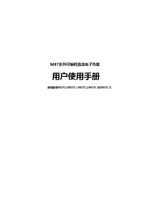
M97系列可编程直流电子负载
用户使用手册
适用型号M9711/M9712/M9712B/M9712C/M9712B30
Maynuo Electronics 2009
目录
第一章 简介...............................................................................................................................................1
4.1.4 定功率操作模式(CW) .......................................................................................................24 4.1.4.1 标准定功率模式...............................................................................................................24 4.1.4.2 加载卸载定功率模式.......................................................................................................25
- 1、下载文档前请自行甄别文档内容的完整性,平台不提供额外的编辑、内容补充、找答案等附加服务。
- 2、"仅部分预览"的文档,不可在线预览部分如存在完整性等问题,可反馈申请退款(可完整预览的文档不适用该条件!)。
- 3、如文档侵犯您的权益,请联系客服反馈,我们会尽快为您处理(人工客服工作时间:9:00-18:30)。
M97系列可编程直流电子负载用户使用手册适用型号M9710/M9711/M9712/M9712B/M9712C版本号:V1.1南京美尔诺电子有限公司版权所有目录第一章 简介 (1)第二章 技术规格 (2)2.1主要技术规格 (2)2.2电子负载尺寸图 (4)第三章 快速入门 (5)3.1开机自检 (5)3.2如果负载不能启动 (5)3.3前面板和后面板介绍 (6)3.4键盘说明 (6)3.5菜单操作 (7)第四章 面板操作 (10)4.1基本操作模式 (10)4.1.1定电流操作模式(CC) (10)4.1.1.1标准定电流模式 (10)4.1.1.2加载卸载定电流模式 (10)4.1.1.3软启动定电流模式 (11)4.1.1.4定电流转定电压模式 (12)4.1.2定电阻操作模式(CR) (12)4.1.2.1 标准定电阻模式 (12)4.1.2.2 加载卸载定电阻模式 (13)4.1.2.3定电阻转定电压模式 (13)4.1.3定电压操作模式(CV) (13)4.1.3.1标准定电压模式 (14)4.1.3.2加载卸载定电压模式 (14)4.1.3.3软启动定电压模式 (14)4.1.4定功率操作模式(CW) (15)4.1.4.1标准定功率模式 (15)4.1.4.2加载卸载定功率模式 (15)4.2动态测试操作 (15)4.2.1连续模式(CONTINUOUS ) (16)4.2.2脉冲模式(PULSE) (16)4.2.3触发模式(TRIGGER) (16)4.2.4 动态测试参数设置 (16)4.2.5波形控制 (17)4.2.5.1方波 (17)4.2.5.2三角波 (17)4.2.5.3梯形波 (17)4.2.6 触发控制 (17)4.2.7 LIST功能 (17)4.2.7.1.编辑LIST列表 (17)4.2.7.2执行LIST功能 (18)4.2.8 自动测试功能 (18)4.2.8.1编辑自动测试列表 (18)4.2.8.2设置自动测试触发输出方式 (19)4.2.8.3执行自动测试功能 (19)4.3输入控制 (20)4.3.1 短路操作(SHORT) (20)4.3.2 输入开关操作 (20)4.4电子负载可操作范围 (20)4.5保护功能 (20)4.5.1 过电压保护(OV) (20)4.5.2 过电流保护(OC) (21)4.5.3 过功率保护(OW) (21)4.5.4 输入极性反接 (21)4.5.5 过温度保护(OH) (21)4.6远端测试功能 (21)4.7蓄电池放电测试操作 (22)4.8快捷方式功能说明 (22)4.9通讯协议 (23)4.9.1 概述 (23)4.9.2 选择通讯波特率 (24)4.9.3 数据 (24)4.9.4 功能码 (24)4.9.5 差错校验 (24)4.9.6 完整命令帧解析 (24)4.9.7 线圈与寄存器地址分配 (26)4.9.8 命令寄存器CMD定义 (28)4.9.9 常用操作功能说明 (28)第一章 简介M97系列产品是美尔诺电子公司设计制造的新一代直流电子负载,采用高性能芯片, 高速,高精度设计,提供0.1mV,0.01mA的解析度(基本精度为0.03%, 基本电流上升速度2.5A/us), 外观新颖,生产工艺科学严谨,相比同类产品,更具性价比。
广泛用于生产线(手机充电器,手机电池,电动车电池,开关电源,线性电源),科研机构,汽车电子,航空航天, 船舶,太阳能电池,燃料电池等行业。
主要特点恒流, 恒阻, 恒压,恒功率, 恒流+恒压, 恒阻+恒压, 六种高速动作模式;过流, 过压, 过功率, 过热,极性反接保护;高亮度,真空,VFD屏, 双排,四路同步显示;根据温度变化,无极伺服, 智能风扇系统;电路软启动时间设定, 可根据设定电压值带载;电池测试及短路功能;提供动态测试,上升下降斜率设定;提供任意波形编辑能力(LIST功能);支持自动测试功能;支持外部触发输入, 输出;提供外部电流波形监视端子;支持远端电压补偿, 多个数据存储;开机自检, 软件校正, 标准仪器架设计;支持GPIB,RS232, RS485, USB通讯。
第二章 技术规格 2.1 主要技术规格2.2 电子负载尺寸图第三章 快速入门3.1开机自检首先用户需要把电源线正确连接并上电,下面是自检的具体步骤。
步骤VFD 显示详细内容当电子负载电源上电后 SYSTEM SELF TESTVx.x 系统自检,并显示软件版本号EPROM ERROR如果EEPROM 损坏或存在EEPROM 中的上次负载的状态丢失,则VFD 显示提示信息(约2S)大约1S 后ERROR CAL.DATA如果存在EEPROM 中的校准数据丢失,则VFD 显示提示信息(约2S)如下如果有有错误提示,则大约2秒后xxxxxxxV xxxxxxxAxxxxxxxW xxxxxxxX VFD显示为实际输入电压、电流、功率、设置参数值及当前状态。
3.2如果负载不能启动用下面的方法可以帮助来解决在打开负载时您可能遇到的问题。
1) 检查电源线是否接好应先检查电源线是否接好,负载是否已经被供电,电源开关是否被打开。
2) 检查负载的电源电压设定负载的工作电压为110V或220V两种方式,检查您的负载的电压设置是否和供电电压相匹配。
3) 检查负载的保险丝是否烧坏若保险丝烧坏,请您用下表中的保险丝规格来替换。
型号 保险丝规格(110VAC) 保险丝规格(220VAC) M9710 T0.5A 250V T0.3A 250V M9711 T0.5A 250V T0.3A 250V M9712 T0.5A 250V T0.3A 250V M9712B T0.5A 250V T0.3A 250V M9712CT0.5A 250VT0.3A 250V4).保险丝的更换方法用平口螺丝刀将负载的后面板上电源输入插座下方的小塑料盖打开,就可以看见保险丝,请使用上述规格相符的保险丝。
(保险丝的位置如下图)图3.1 保险丝位置3.3前面板和后面板介绍M97系列电子负载前面板如下图所示图3.2 前面板图① 面板的上半部分为黑色VFD 显示屏和旋钮② 面板的下半部分从左至右依次为0-9数字键和ESC 退出键 ,功能按键,上下移动键和Enter 键,输入和输出端子。
M97系列电子负载后面板如下图所示0-满量程电流,对应0-10V 输出,可接示波器,看动态波形远端量测端子,触发输入输出接口多功能通讯接口,GPIB, RS232, RS425, USB 转接3.4键盘说明1233.5菜单操作按下Shift+Menu键后进入菜单功能,此时VFD上显示出可选择菜单,可使用上下操作键▽ 和 △或旋钮来翻转VFD屏幕,将依序出现以下功能。
此时按下Enter键,将会进入光标所在位置的功能选项,可使用上下操作键▽ 和 △或旋钮来翻转VFD屏幕,按下Enter键就可以进入下一级子菜单。
按 Esc键返回上一层菜单。
MENUCONFIGINPUT RECALL 设置负载上电时的输入状态为上次关机时的状态或者为OFF 状态ON 负载开机时,恢复为关机前的状态。
OFF 负载开机时,输入状态为OFF,工作模式为CC。
KEY SOUND SET 键盘声音设置ON 键盘有声音OFF 键盘无声音CONNECT MODE 连接模式MAXTIDLEXING 多台SEPARATE 单台BAUDRATE SET 设置通讯波特率24009600144002880057600115200COMM.PARITY 设置通讯校验方式NONE 无校验EVEN 偶校验ODD 奇校验ADDRESS SET 设置负载通讯地址1~200KEY LOCK SET 设置键盘解锁密码(为空或0时表示不设密码)EXITSYSTEM SETMAX CURRENT SET 设置软件电流上限,若电流上限大于最大电流的1/10,电流为高量程,否则为低量程(如120A机器,12A以下为低量程档)MAX VOLTAGE SET 设置电压上限,若电压上限大于20V,则电压为高量程,否则为低量程MAX POWER SET 设置功率上限TERMINAL SEL 输入端子选择FRONT 选择前面板端子输入BACK 选择后面板端子输入EXITLISTLOAD LIST 选择LIST文件,1~8EDIT LIST 编辑LIST文件MINIMUM TIME 编辑最小时间细度(0.02~1310.7mS)LIST MODE LIST输出模式CONTINUOUS 连续输出END HOLD 输出结束保持最后的输出电平END RESET 输出结束保持空载输出STEP LENGTH 总步长(1~200)STEP n 1~总步长CURRENT 设置电流TIME 持续时间EXITAUTO TESTLOAD AUTO TEST 选择自动测试文件1~8EDIT AUTO TEST 编辑自动测试文件STEP LENGTH 设置总步长STEP nWORK MODELOAD OFF MODE 空载模式CC MODE 定电流模式CV MODE 定电压模式CP MODE 定功率模式CR MODE 定电阻模式SHORT MODE 短路模式TEST MODE 合格性测试模式TEST CURRENT 测试电流TEST VOLTAGE 测试电压TEST POWER 测试功率TEST RESI 测试电阻DELAY TIME 测试延时时间(0.2~25.5S)INPUT xxxx 输入设定参数,比如CC模式1AMINIMUM xxxx 输入测试参数下限MAXIMUM xxxx 输入测试参数上限SETUP AUTO TESTTRIGGER 触发输出选择WHEN PASS 当测试通过时,启动触发输出WHEN FAIL 当测试失败时,启动触发输出WHEN TEST END 当测试完成时,启动触发输出DISABLE 禁止触发输出OUTPUT 输出电气特性选择PULSE 脉冲输出LEVEL 电平输出EXITEXIT第四章 面板操作4.1基本操作模式电子负载可以工作在下面四种模式中:1. 定电流操作模式 (CC).2. 定电压操作模式 (CV).3. 定电阻操作模式 (CR).4. 定功率操作模式 (CW)4.1.1定电流操作模式(CC)在定电流模式下,不管输入电压是否改变,电子负载消耗一个恒定的电流,如下图所示。
请注意,如果待测源能够输出的最大电流值小于设定的定电流值,负载将不能保证调整为设定电流值,待测源电压也可能会被拉低。
Load currentIVLoad voltage图4.1 定电流模式4.1.1.1标准定电流模式按I-SET按键,负载显示“STANDARD CURR=xxxxxxxxA”,提示当前定电流值,此时可以按面板上的数字键与小数点键,从高位到低位依次输入所需的定电流值,并按Enter键确认,负载进入标准定电流模式。