
模拟式控制器(精选)
REX-C100 系列 模拟式温度控制器 说明书

Notes:Make sure that this Instruction Manual is always readily available to personnel who use the REX-C100 series.The contents of the Instruction Manual are subject to change without notice. If you have any questions regarding the manual,contact one of our sales people, our nearest sales office, or the place where you have purchased the controller.1.PRODUCT CHECKCheck whether the delivered product is as specified by referring to the following model code list.OModel codeC100 QQQ - Q ~ QQÎ Ï Ð Ñ Ò ÓÎControl actionÓSecond alarm [ALM2]F : PID action [Reverse action]N : No second alarmD : PID action [ Direct action]A : Deviation high alarm *2B : Deviation low alarm *2ÏInput typeC : Deviation high / low alarm *2See input range table “Model code” page 9D : Band alarmE : Deviation high alarm *3ÐInput rangeF : Deviation low alarm *3See input range table “Model code” page 9G : Deviation high / low alarm *3H : Process high alarm *2ÑControl output [OUT]J : Process low alarm *2M : Relay contact K : Process high alarm *3V : Voltage pulseL : Process low alarm *38 : Current 4 to 20mA DCP : Heater break alarm (CTL-6)G : Trigger (for triac driving) *1S : Heater break alarm (CTL-12)R : Control loop break alarm *4ÒFirst alarm [ALM1]N : No first alarm*1When control output is trigger output A : Deviation high alarm *2for triac driving, only the first alarm isB : Deviation low alarm *2available.C : Deviation high / low alarm *2*2Without hold action.D : Band alarm*3With hold actionE : Deviation high alarm *3*4As control loop break alarm, only eitherF : Deviation low alarm *3the first alarm or second alarm is G : Deviation high / low alarm *3selected.H : Process high alarm *2J : Process low alarm *2CConfirm that power supply voltage is alsoK : Process high alarm *3the same as that specified when ordering.L : Process low alarm *3R : Control loop break alarm *4Accessories C Mounting brackets (2 pcs.)CInstruction manual(1 copy)REX-C100SERIESINSTRUCTION MANUALFig. 1Fig. 22.MOUNTING •DimensionsUnit : mm (inch)* Dimensions in inches are shown for reference•Mounting proceduresThickness of panel board:1 to 5mm or 5 to 9mm (0.04 to 0.20 inch or 0.20 to 0.35 inch)uWhen the controllers are mounted on panel with 1 to 5mm in thickness ÎMake a rectangular cutout corresponding to thenumber of controllers to be mounted on panel by referring to the panel cutout dimensions.ÏSince the mounting brackets are already installed onthe controller, insert the controller into the panel from the panel front without removal of the brackets (Fig. 1).uWhen the controllers are mounted on panel with 5 to 9m in thickness ÎRemove the mounting brackets from the controllerwith a slotted screwdriver.ÏEngage each mounting bracket with holes markedwith “5.9" on the housing (Fig. 2) and then insert the controller into the panel from the panel front.OCautions for mountingMo untingbracketAvoid the following location where the controller is mounted.C Location where ambient temperature is more than 50E C (122E F) or less than 0E C (32E F).C Location where humidity is high.C Location where corrosive gas is generated.C Location where strong vibration and shock exist.C Location where flooding and oil splash exist.C Location where much dust exists.CLocation where inductive disturbance is large and otherlocation where bad influence is exerted on electric instrument.3.WIRING•Rear terminalsNotes1.Terminals which are not used according to the controller type are all removed.2.For thermocouple input, no metal piece is attached to terminal No. 10. Instead, the temperature compensationelement in the internal assembly is projected through a hole at terminal No. 10.Do not damage the above temperature compensation element when the internal assembly is removed from the case.O Cautions for wiring(1)Conduct input signal wiring away from instrument, electric(3)For wiring, use wires conforming to domesticequipment power and load lines as such as possible to avoid standard of each country.noise induction.(4)About 5 to 6 sec. are required as the(2)Conduct instrument power wiring so as not to be influenced preparation time of contact output duringby noise from the electric equipment power.power ON. Use a delay relay whenthe outputIf it is assumed that a noise generation source is located near line, is used for an external interlock circuit.the controller and the controller is influenced by noise, use anoise filter (select the filter by checking instrument power(5)The figures below show the REX-C100 circuit supply voltage.)configuration. When connecting wires, notethat the power, input, MCU and output circuitsC Sufficient effect may not be obtained depending on the are isolated independently, while the inside offilter. Therefore, select the filter by referring to its the input and outputcircuits are not isolated.frequency characteristic, etc.ÎFor instrument power wiring, if it is assumed that noiseexerts a bad influence upon the controller, shorten thedistance between twisted power supply wire pitches.(The shorter the distance between the pitches, the moreeffective for noise reduction).ÏInstall the noise filter on the panel which is alwaysgrounded and minimize the wiring distance between thenoise filter output side and the controller power terminals.Otherwise, the longer the distance between output sideand instrument power terminals, the less effective for REX-C100 circuit configurationnoise.ÐDo not install fuses and / or switches on the filter outputsignal since this may lessen filter effect.WIRING AND NAME OF PARTS•Wiring exampleREX-C100F GG-M*-~2N-HA OF PARTSÑSet-value increment keyC Used when the number needs to be increasedfor set-value change.ÒMeasured-value (PV) display unit [Green]C Displays measured-value (PV)C Displays a parameter symbol in the parametersetting mode.ÓSet-value (SV) display unit [Orange]C Displays set-value (SV)C Displays set-value corresponding to theparameter symbol displayed on the measured-value (PV) display unit.ÎSet (SET) keyC The set-value thus changed is enteredÔControl output (OUT) lamp [Green]C Parameters in the parameter setting mode are C Lights up when the control output is turnedON.selected in due order.C Can select PV / SV display mode, SV settingÕAuto-tuning (AT) lamp [Green]mode, and parameter setting modes.C Flashes during auto-tuning.ÏSetting digit shift keyÖFirst alarm (ALM1) lamp [Red]C Used when the cursor (brightly lit) is moved to C Lights up when the first alarm is turned ON.the digit whose number needs to be changed for C When a control loop break alarm (LBA) is set-value change.selected as the first alarm, this lamp lights up.ÐSet-value decrement key×Second alarm (ALM2) lamp [Red]C Used when the number needs to be decreased C Lights up when second alarm is turned ON.for set-value change.C When either a heater break alarm (HBA) orcontrol loop break alarm (LBA) is selected asthe second alarm, this lamp lights up.5.OPERATION•Calling-up procedure of each mode:Press the key.Input type code / input range displayThis controller, with the power turned ON, displaysautomatically the input type code on the measured-value (PV)display unit and the input range, on the set-value (SV) displayunit, respectively.Example : For a controller with the K thermocouple inputtype and input range from 0 to 1372E C.ÎDisplays the input type code.: Indicates input abbreviation.unit. ( : E F)input type code table).ÏDisplays the input range.< Input type code >Code Input Type Code Input typeRSBW5Re/W26RePLIIPt100JPt100PV / SV display modeC Displays measured-value (PV) on the measured-value(PV) display unit and set-value (SV) on the set-value (SV)display unit. Usually the control is set to this modeexcepting that the set-value (SV) and/or the parameter set-value are changed.PV / SV display modeC Pressing the key lights the least significant digit onvalue (SV).In order to register the value whose setting was changed,always press the key after the value is changed.sec. in the PV / SV display or SV setting mode, thecontroller is set to the parameter setting mode.C Parameters in the parameter setting mode changes in dueorder every time the key is pressed (See page 6).and keys are pressed.C In order to register the value whose setting was changed,press the key after change to shift to the nextsec.•When no key is operated for more than 1 minute.•Parameter typesThe following parameter symbols are displayed one by one every time the key is pressed.Current transformer input (CT)Setting is not possible.Set heater break alarm value byreferring to this value.Display input value from thecurrent transformerCTSecond alarm Set alarm set-value of second alarm.AL2Control loopbreak alarm (LBA)0.0 to 200.0 min.Set control loop break alarmset-value.Cannot be set to “0.0".8.0LbAAuto-tuning (AT)0 : Auto-tuning end or stop1 : Auto-tuning startTurns the auto-tuningON/OFF.ATUIntegral time (I)1 to 3600 sec.Eliminates offset occurringcontrol is performed. I actionturns OFF with I set to “0".240IAnti-reset windup (ARW)1 to 100% of proportional band.Prevents overshoot and/orundershoot caused by integralaction. I action turns OFFwith this action set to “0".100ArSet data lock 0100 : No set data locked (Allparameters changeable)0101 : Set data locked (All parametersnot changeable)0110 : Only the set-value (SV) ischangeable with the set data locked.Performs set data changeenable / disable.0100LCK* The second alarm (or first alarm), heater break alarm, control loop break alarm parameter symbols are not simultaneously displayed. * Heater break alarm is not available on a current output.C Parameter setting procedure Setting set-value (SV)Following is an example of setting the set-value (SV) to 200E C. (PV : 30E C)Î Set to the set modeÏ Shift of the digit brightly litÐ Set-value increase or decrease ÑSet-value entryPress the key to Press the key to shift Press the key to set “2".After finishing the setting,enter the SV setting mode.the digit which lights brightlypress thekey. All ofController returns to the PV/SV display mode.Example : When a temperature of 199E C is changed to 200E C.Set-value increase or decreasePress the key to shift the digit brightly lit to the least significant digit. Press the key to change “9" to “0", therebyobtaining 200E C. The same applies to set-value decrease.Example : For changing 200 to -100.Minus (-) value settingPress the key to shift the digit brightly lit to the hundreds digit. Press the key to decrement figures in order of÷ 0 ÷ -1.Setting parameters other than set-value In the PV/SV display modeIn the parameter setting modeKey operational cautions CFor this controller, the value whose setting was changed is not registered. It is registered for the first time it is shifted to the next parameter by pressing the key.setting mode, set data lock is activated.In this case, change the “” parameter set-value to “0100".the parameter setting mode.Press thekey by the required number of times untilkey after the setting is finished in the parameters).When no parameter setting is required, return the controller to the PV/SV display mode.¬Pay attention to the following when the parameters described below are set.Auto-tuning (AT)C Prior to starting the auto-tuning function, end all the parameter settings other than PID and control loop break alarm(LBA).Heater break alarm (HBA)C Set heater break alarm set-value to a value about 85% current transformer input value. However, when power supplyvariations are large, set the alarm to a slightly smaller value.In addition, when two or more heaters are connected in parallel, set the alarm to a slightly larger value so that it is activated even with only one heater is broken. (However, within the value of a current transformer input value).C When the heater break alarm set-value is set to “0.0" or the current transformer is not connected, the heater breakalarm is turned ON.Control loop break alarm (LBA)C Usually set the set-value of the LBA to a value twice the integral time (I).O Set data locking procedureThis controller is provided with a set data locking function which disables each set-value change by the front key and also the auto-tuning function. Use this function for malfunction prevention at the end of each setting.C Press the key by the required number of(PV) display unit.C Press the , and keys to set the•Display at error occurrence< Heater break alarm >Display CauseMeasure(Lights)C Controlled object trouble (No power supply,incorrect wiring, etc).C Sensor trouble (Sensor disconnected, shorted, etc).C Actuator trouble (Weld relay contact, incorrectwiring, relay contact not closed, etc).C Output circuit trouble (Weld internal relay contact,relay contact not opened or closed, etc).C Input circuit trouble (The measured-value does notchange even if input changes, etc).Control system check(Error cause cannot bespecified)Check whether there is no effectby disturbances (Other heatsource, etc).LBA set time check< Overscale, Underscale >Input type Input display rangeTCK-30 to +1372E C -30 to +2502E F J-30 to +1200E C -30 to +2192E F R, S-30 to +1769E C -30 to +3216E F B-30 to +1820E C -30 to +3308E F E-30 to +1000E C -30 to +1832E F T-199.9 to +400.0E C -199.9 to +752.0E F N-30 to +1300E C -30 to +2372E F PLII-30 to +1390E C -30 to +2534E F L-30 to +800E C -30 to +1600E F U-199.9 to +600.0E C -199.9 to +999.9E F W5Re/W26Re-30 to +2320E C -30 to +4000E FRTDPt100JPT100-199.9 to +649.0E C Pt100-199.9 to +999.9E F。
模拟式控制器
将变速器送来的1-5V.DC的测量信号,与1-5V.DC的给 定信号进行比较得到偏差信号,然后再将其偏差信号 进行PID运算,输出4-20mA.DC信号,传递给执行器, 实现对过程参数的自动控制。
5.3 DDZ—Ⅲ型电动控制器的组成与操作 Ⅲ
图4-3-13 DTL-3110型调节器正面图 1—自动-软手动-硬手动切换开关;2—双针垂直指示器;3—内给定设定轮; 4—输出指示器;5—硬手动操作杆;6—软手动操作板键;7—外给定指示 灯;8—阀位指示器;9—输出记录指示;10—位号牌;11—输入检测插孔; 12—手动输出插孔
13
5.3 模拟式控制仪表
(3)Ⅲ型仪表统一由电源箱供给24V DC电源,并有蓄电 型仪表统一由电源箱供给24V DC电源 电源, 池作为备用电源。 池作为备用电源。
优点
各单元省掉了电源变压器,没有工频电源进入 单元仪表,既解决了仪表发热问题,又为仪表的 防爆提供了有利条件。 在工频电源停电时备用电源投入,整套仪表在 一定时间内仍可照常工作,继续进行监视控制作 用,有利于安全停车。
12
5.3 模拟式控制仪表
(2)广泛采用集成电路,可靠性提高,维修工作量减少。 广泛采用集成电路,可靠性提高,维修工作量减少。
优点
由于集成运算放大器均为差分放大器,且输入 对称性好,漂移小,仪表的稳定性得到提高。 由于集成运算放大器有高增益,因而开环放大 倍数很高,这使仪表的精度得到提高。 由于采用了集成电路,焊点少,强度高,大大 提高了仪表的可靠性。
15
DDZ-II型仪表 - 型仪表 调节器) (包括调节器) 包括调节器
DDZ一III型仪表 一 型仪表 调节器) (包括调节器) 包括调节器
III型仪表优点 型仪表优点
pid控制PPT课件
k
Kpe(k)Ki e(j)Kde(k)e(k1) j0
式中,u(k)为第k次采样时刻的控制器的输出值; e (k-1)和e (k)分别为第(k-1)次和第k次采样时刻的偏差值。
只要采样周期T足够小,数字PID控制与模拟PID控制就会十分
精确的接近。
ppt精选版
12
1.2.2 增量式PID控制算法
e(k )
0 e(k )
e(k) e0 e(k) e0
式中,e(k)为位置跟踪偏差,e0是一个可调参数,其 具体数值可根据实际控制对象由实验确定。若e0值 太小,会使控制动作过于频繁,达不到稳定被控对象
的目的;若e0太大,则系统将产生较大的滞后。
ppt精选版
35
1.2.9 带死区的PID控制算法
1.1 PID控制原理
闭环控制系统原理框图
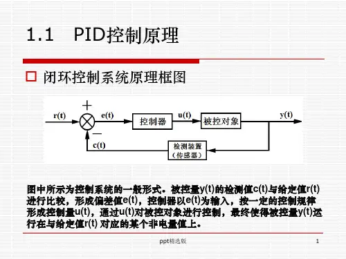
图中所示为控制系统的一般形式。被控量y(t)的检测值c(t)与给定值r(t) 进行比较,形成偏差值e(t),控制器以e(t)为输入,按一定的控制规律 形成控制量u(t),通过u(t)对被控对象进行控制,最终使得被控量y(t)运 行在与给定值r(t) 对应的某个非电量值上。
ppt精选版
1
1.1 PID控制原理
模拟PID控制系统原理框图
ppt精选版
2
ppt精选版
3
1.1 PID控制原理
PID控制器各环节的作用如下:
(1)比例环节的数学式表示是:
Kp e(t)
在模拟PID控制器中,比例环节的作用是对偏差量e(t)瞬间 作出反应, 产生相应的控制量u(t),使减少偏差e(t)向减小的 方向变化。控制作用的强弱取决于比例系数Kp, Kp越大, 控制作用越强,则过渡过程越快,控制过程的静态偏差ess 也就越小,但是Kp越大,也越容易产生振荡,增加系统的超 调量,系统的稳定性会变差。
3.2 模拟及数字控制器
它吸收了整体式和模块式PLC的优点,其基本单元、扩展 单元等高等宽,它们不用基板,仅用扁平电缆连接,紧密拼装 后组成一个整齐的体积小巧的长方体,而且输入、输出点数的 配置也相当灵活。
按功能分类:
低档PLC,中档PLC,高档PLC
特点:
• 可靠性高、抗干扰能力强。 • 编程简单、使用方便。 • 功能完善、通用型强。 • 设计安装简单、维护方便。 • 体积小、质量轻、能耗低。
二、数字式控制器的基本构成
1.硬件电路
图4-19 数字式控制器的硬件电路
(1)主机电路 主机电路是数字式控制器的核心,用于实现仪表数据运算
处理及各组成部分之间的管理。 (2)过程输入通道
过程输入通道包括模拟量输入通道和开关量输入通道,模拟量输 入通道用于连接模拟量输入信号,开关量输入通道用于连接开关量输 入信号。 (3)过程输出通道
当低于液位下限时,下限开关与上限开关均断开,0.00与0.01常闭 触点闭合,使输出继电器10.00导通,注水电磁阀打开;一旦超过下限 液位,虽然0.01触点断开,但由于10.00触点的自锁作用,仍保证注水 阀打开,直至上限检测开关闭合,0.00的常闭触点断开,输出继电器 10.00断开,注水阀关闭。
三、XMGA5000/XMGA6000系列数字控制器
可以接收四个模拟输入 信号,两个模拟量输出信号, 1个开关量输入,三个继电器 输出和先进的专家自整定PID 控制算法。
XMGA5000/XMGA6000的外形图
优点
功能强大;
能用于单回路的简单控制系 统与复杂的串级控制系统;
控制精度高、使用方便灵活;
小型PLC分为C120和C200H两种,C120最多可扩 展256点I/O,是紧凑型整体结构。
S7-300程序设计方法(模拟量控制)本月修正简版

S7-300程序设计方法(模拟量控制)S7-300程序设计方法(模拟量控制)1. 简介本文档旨在介绍S7-300程序设计中的模拟量控制方法。
S7-300是西门子(Siemens)公司生产的一种工业自动化控制器,广泛应用于工业控制领域。
2. 模拟量控制概述模拟量控制是指对连续变化的物理量进行监测和调节的过程。
在工业自动化中,模拟量通常用来表示温度、压力、液位等连续变化的物理量。
S7-300控制器具备良好的模拟量输入和输出接口,可实现对模拟量的监测和调节。
3. S7-300模拟量输入配置在S7-300控制器中,模拟量输入通过配置模拟量输入模块来实现。
下面介绍一般的模拟量输入配置过程:3.1. 选择适当的模拟量输入模块根据需求选择合适的模拟量输入模块,通常有不同的输入通道数和精度可供选择。
3.2. 连接模拟量输入模块将模拟量输入模块与控制器连接。
通常采用总线或直接连接方式。
3.3. 配置模拟量输入模块在S7-300控制器的编程软件中,进行模拟量输入模块的参数配置。
包括输入通道数、量程范围、采样周期等。
3.4. 读取模拟量输入数值在PLC程序中,通过相应的指令读取模拟量输入模块的数值。
可以根据需要进行处理和判断,进一步实现对模拟量的监测和控制。
4. S7-300模拟量输出配置S7-300控制器不仅支持模拟量输入,还支持模拟量输出。
下面介绍一般的模拟量输出配置过程:4.1. 选择适当的模拟量输出模块根据需求选择合适的模拟量输出模块,通常有不同的输出通道数和分辨率可供选择。
4.2. 连接模拟量输出模块将模拟量输出模块与控制器连接。
通常采用总线或直接连接方式,需要注意与输入模块的通道对应。
4.3. 配置模拟量输出模块在S7-300控制器的编程软件中,进行模拟量输出模块的参数配置。
包括输出通道数、输出范围、初始值等。
4.4. 写入模拟量输出数值在PLC程序中,通过相应的指令将需要的模拟量输出数值写入输出模块。
可以根据需要实现对模拟量的精确控制。
第4章 控制器

8
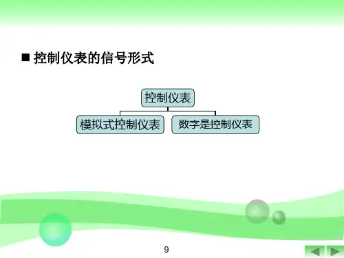
20世纪80年代以来,又发展了数字调节器:可编程调节器、智 能调节器,基于集散控制系统或者现场总线的控制器等。以微处理 器为基础,功能完善,性能优越,能够解决模拟式仪表难以解决的 问题。近二十年来数字式控制仪表不断涌现新品种应用于过程控制 中,以提高控制质量,对整个控制系统产生革命性变革。 电动模拟式、数字式调节器,具有反应快,信号易远传,容易与 其他仪表相配套,功能丰富,符合当今仪表的发展趋势。基于集散控 制系统或者现场总线的控制器,它们除了控制功能外,还具有网络 通信等功能,适应信息社会大规模生产需要。
27
想一想,为什 么不从0开始?
特点——
1)采用统一信号标准:4~20mA DC和1~5V DC。 这种信号制的主要优点是电气零点不是从零开始, 容易识别断电、断线等故障。同样,因为最小信号 电流不为零,可以使现场变送器实现两线制。 2)广泛采用集成电路,仪表的电路简化、精度提高、 可靠性提高、维修工作量减少。 3)可构成安全火花型防爆系统,用于危险现场。
手/自动双向切换 手动操作 无扰动切换 Kp/Ti/Td的设置 Kp/Ti/Td的设置
一般在刚刚开车时采用手动控制,待系统正常时切换到自动控制。 可以调整手操拨盘或者手操扳键来改变调节器的输出 手自动切换时都希望不给控制系统带来扰动,即调节器的输出信号 不发生突变(即必须要求无扰动切换) 改变控制器的特性
DV
21
22
比例积分微分调节规律(PID): 同时具有比例、积分、微分三种控制作用的控制器称为比例积分 微分控制器。 微分控制器 1 dDv Mv Kp Dv Dvdt T D T dt I 对阶跃偏差:微分先起主导作用,使输出 大幅度变化,产生强烈的调节作用之后微 分作用消失,积分逐渐占主导地位,直到 余差完全消失,积分作用才停止。 若将TD=0,微分作用消失——PI调节器 TI=无穷大,积分作用消失——PD调节器 TD=0,TI=无穷大——P调节器。
AHU系统中模糊自整定PID控制器模拟
AH U系统中模糊自整定PID控制器模拟华中科技大学沈国民m舒刚中南建筑设计院王春香摘要以M atlab/Simulink为基础,对集中空调常用的AH U控制系统进行了仿真研究。
设计了一种模糊自整定Fuzzy-PID控制器,并与传统的PID控制器进行了比较,指出模糊PID 控制器具有控制精度高、超调量小的优点,对对象参数的变化具有很好的适应性和鲁棒性,适合在具有非线性、时变性和时间滞后性的空调温控系统中应用。
关键词空气处理机组PID控制模糊自整定温度控制Simulation of fuzzy sel-f tuning PID control in AHU systemB y S hen G uomin n,S hu G ang and Wang Ch unxiangAbstract Ba sed on the M atla b/Simulink,sim ulates a ir handle units(A HU)comm only used in centra l air condit io ning sy stem,and dev elo ps a fuzzy se lf-tuning PID co ntr o l sy stem.By co mpar ing f uzzy-PID contr o l and conv entional PI D co ntr ol,f inds that the f or mer contr o l has higher pr ecisio n,sma ller o ver sho o t, and the me thod has f avo r able a da pt ability,r o bustness and disturbance-r ejectio n espec ially w he n the para meter s o f the o bject ar e change d,and can ef fec tiv ely contr ol the air co nditio ning syste m which is nonlinear,fr equently va riable a nd time-delaying.Keywords A HU,PI D co ntr ol,f uzzy self-tuning,temper atur e co ntr oln Huaz hong University of Sci ence and Technology,Wuhan,China0引言空气处理机组AH U是集中空调系统中最常见的设备,集中空调系统的控制很大程度上也是对AH U的控制。
模拟式PID调节电路
模拟式P I D调节电路(总24页)-CAL-FENGHAI.-(YICAI)-Company One1-CAL-本页仅作为文档封面,使用请直接删除湖南文理学院课程设计报告课程名称:电子技术课程设计院系:电气与信息工程学院专业班级:学生姓名:指导教师:完成时间:报告成绩:模拟式PID 调节电路的研究目录摘要........................................................................................................................................................................ ABSTRACT . (I)第一章模拟式PID调节电路结构 01.1基于PID调节规律的PID调节电路结构 01.2PID调节电路结构之比较 0第二章并联式模拟PID调节电路单元分析 (2)2.1PID调节电路单元的基石 (2)2.1.1 反相比例电路 (2)2.1.2 积分电路 (3)2.1.3 基本微分电路 (4)2.2调节单元电路分析 (5)2.2.1 比例调节(P调节) (5)2.2.2 比例积分调节(PI调节) (6)2.2.3 比例微分调节(PD调节) (7)2.2.4比例积分微分调节 (8)2.3数字式调节模式选择单元分析 (9)第三章基于MULTISIM10的模拟式PID调节电路的仿真 (10)3.1积分、微分电路的仿真 (10)3.1.1 积分电路的阶跃响应及频率特性 (10)3.2.2 微分电路的阶跃响应及频率特性 (11)3.2并联式模拟PID调节单元仿真 (11)3.2.1 数字式调节模式选择单元仿真 (11)3.2.2 P调节电路的阶跃响应 (12)3.2.3 PD调节电路的阶跃响应 (12)3.2.4 PI调节电路的阶跃响应 (12)3.2.5 PID调节电路的阶跃响应 (12)总结 (15)参考文献 (16)致谢 (17)附录1 并联式模拟PID调节仿真电路 (18)附录2 并联式模拟PID调节电路 (19)附录3 并联式模拟PID调节电路元件明细表 (20)PID调节规律是自动控制系统中常见而典型的控制策略,其中模拟式PID器是最基本的实现手段与方式。
thx11-模拟式控制器
1. 数字式控制器的主要特点
1.数字式控制器的主要特点 • 实现了模拟仪表与计算机一体化; • 具有丰富的运算控制功能; • 使用灵活方便,通用性强; • 具有通讯功能,便于系统扩展; • 可靠性高,维护方便。 2.数字式控制器的基本构成 • 由硬件电路和软件两大部分组成,其控制功能主要是由软 件所决定。 (1)硬件电路:由主机电路、过程输入通道、过程输出通道、 人机接口电路以及通信接口电路等部分组成。 图4-19(P123)数字式控制器的硬件电路
2. 数字式控制器的基本构成
2. 数字式控制器的基本构成
• 主机电路用于实现仪表数据运算处理及各组成部分之间的 管理; • 过程输入通道包括模拟量输入通道和开关量输入通道,分 别用于连接模拟量输入信号和开关量输入信号。 • 过程输出通道包括模拟量输出通道和开关量输出通道,分 别用于输出模拟量信号和开关量信号。 • 人机接口电路用于人机联系。(有按钮、数据显示和状态 显示等) • 通信接口电路用于信号的发送和接收。 (2)软件:包括系统软件和用户软件。 • 系统软件:由监控程序和功能模块组成,分别管理控制器 各部分的工作和提供各种功能; • 用户软件:是用户根据控制系统的要求,进行组态,以完 成预定的控制与运算功能。
§4 数字式控制器
【引】数字式控制器采用数字技术,以微处理机为核心部 件;备有A/D和D/A器件,而在外观、体积、信号制上都与 DDZⅢ型控制器相似或一致,也可装在仪表盘上使用,且 经常只用来控制一个回路(包括复杂控制回路),故又常 称之为单回路数字控制器。
1. 数字式控制器的主要特点 2. 数字式控制器的基本构成★ 3. 智能调节仪
Chap5自动控制仪表
§3 模拟式控制器 §4 数字式控制器
§3 模拟式控制器
第三章模拟式控制器
比例积分调节器是比例作用和积分作用的叠加,其动态方程 为:
0 edt
t
或写成
1 1 e Ti
0 edt
t
KP 其中:Ti KI
比例积分(PI)调节器的传递函数为:
WPI
KI 1 1 1 s KP s Ti s
μ的变化,使被调量最终等于给定值。调节器的输出量与输
入量之间的动态关系, 称作调节器的控制规律。调节器和被
控对象组成的一个闭合控制回路如下图所示: λ
EXIT
+
r
e
调节器
μ
被控对象
y
第15页
3.1 .1 基本调节作用
调节器的控制规律中最基本的调节作用是比例、积分和微分 作用 , 它们各有其独特的作用,下面分别讨论。
操作转换器
手动 自动
Ii If
伺服放大器
伺服 电动机
位置变送器
电流表
机 械 减 速 器
第11页
伺服放大器
EXIT
执行机构
伺服放大器作用:综合输入信号和反馈信号,并将该结果 信号加以放大,使之有足够大的功率来控制伺服电动机的转动。 根据综合后结果信号的极性,放大器应输出相应极性的信 号,以控制电动机的正、反运转。 伺服电机:是执行机构的动力部分 减速器 :将高转速、低转矩变成低转速、高转矩 位置变送器:根据差动变压器的工作原理,利用输出轴 的位移来改变铁芯在差动线圈中的位置,以产生反馈信号和 位置信号。
EXIT
第28页
对下图所示单回路系统,保持控制对象不变化,当调节器 分别采用P、PI控制时,若保证稳定性相同(ψp= ψ PI=0.75)
r + e WT (s)