如何防止ISE综合时信号被优化掉
网络优化的常见问题与解决方法

网络优化的常见问题与解决方法网络优化是指通过技术手段对网络进行改进,以提高网络的性能、稳定性和可用性。
随着互联网的快速发展,网络优化也变得越来越重要。
然而,在进行网络优化的过程中,常常会遇到一些问题。
本文将介绍网络优化的常见问题,并给出相应的解决方法。
一、网络延迟问题网络延迟是指数据传输过程中所需的时间延迟。
网络延迟较高会导致网络连接变慢,影响用户的体验。
造成网络延迟的原因有很多,比如网络拥塞、数据包丢失、网络设备故障等。
解决网络延迟问题的方法包括以下几点:1. 使用CDN加速技术:CDN(内容分发网络)可以将用户请求的资源分发到离用户最近的节点,减少数据传输的距离,从而提高性能。
2. 优化网络设备:及时升级网络设备的固件版本,确保设备工作在最新的性能状态下。
3. 避免网络拥塞:对于网络拥塞的情况,可以增加带宽、分流流量、限制某些特定的网络服务等方式来解决。
二、数据丢失问题数据丢失是指在数据传输过程中,部分或全部数据丢失的情况。
数据丢失会导致网络连接不稳定,影响数据的完整性和可靠性。
以下是几种解决数据丢失问题的方法:1. 使用可靠的传输协议:例如TCP(传输控制协议)具有数据校验和流量控制的功能,可以保证数据的可靠传输。
2. 使用冗余技术:通过冗余技术,可以将数据在多个路径上传输,当某一路径发生故障时,可以通过其他路径传输数据,从而避免数据丢失。
3. 定期备份数据:为了防止数据丢失,应该定期备份重要数据,以确保数据的安全性和可恢复性。
三、网络安全问题网络安全问题是指网络在数据传输和通信过程中面临的安全隐患。
网络安全问题可能导致数据泄露、黑客攻击、病毒传播等风险。
以下是几种解决网络安全问题的方法:1. 使用防火墙:设置防火墙可以过滤非法的入侵请求,保护网络和数据的安全。
2. 更新安全补丁:定期更新操作系统和软件的安全补丁,以修复已知的安全漏洞,加强系统的能力。
3. 加密数据传输:使用SSL(安全套接层)协议对数据进行加密,确保数据在传输过程中不被窃取或篡改。
优化与防止被优化
注册登录•论坛•搜索•帮助•导航SoC Vista -- IC/FPGA设计家园» 30分钟必答 - 无限制提问专区» 设计未完成阶段进行面积评估如何防止被优化12下一页返回列表回复发帖mentor00超级通吃版主1#打印字体大小: t T发表于 2009-11-8 09:48 | 只看该作者设计未完成阶段进行面积评估如何防止被优化(本文来自anthonyyi的来信。
请大家一起来解答。
)为了对整个设计进行性能和面积的评估在模块尚未全部完成的阶段进入FPGA综合阶段在顶层设计中instance了所有已完成的模块但这些模块中有的由于后续模块没有完成,其输出悬空,即没有load在Synplify下使用Syn_noprune属性发现在compile阶段能保留上述模块,其RTL view显示模块存在在map之后观测Technology view发现上述模块已经被优化掉只剩下输入端口,且无drive故综合报告无实际意义和参考价值想请教在如何不改变顶层模块的输出管脚而使综合保留上述无输出的模块个人想到一种,用syn_probe将输出net probe出来,但这样会有风险因为综合工具似乎只会保留这些与该输出有关的逻辑而优化掉其他的部分而且该步骤没有进行实战确认:(本主题由 admin 于 2009-12-2 07:56 加入精华收藏分享评分回复引用订阅 TOPmentor00超级通吃版主2#发表于 2009-11-8 10:04 | 只看该作者我想可以参考一下下面的转载内容提问:我使用的是synplify pro综合verilog语言,例化了一个BUF,在综合结果里也看到了这个BUF,但是在MAP是这个BUF还是被优化掉了,请问用什么方法将这个BUF保留下来?解答:在这个BUF两端的信号线上加上下面的属性——wire bufin /* synthesis syn_keep=1 xc_props="X" */;wire bufout /* synthesis syn_keep=1 xc_props="X" */;解释下:1、syn_keep=1就是保留这个信号线,是它成为一个instance(synplify的),然后就可以对它添加XILINX的约束属性;2、xc_props=“”是synplify为XILINX保留留的约束属性,可以透传到ISE的实现中去,从而约束实现过程。
quartus中如何保持信号不被综合掉
quartus中如何保持信号不被综合掉在一些应用中,有些特定的信号我们需要保留,用于进行采集检测,而综合器会自动优化把它综合掉,那么,应该怎样告诉综合器,不让它优化掉我们需要保留的信号呢?对这种情况的处理是增加约束,共有2种情况:1、需要保留的信号是引线Verilog HDL—定义的时候在后面增加/* synthesis keep */。
例如:wire keep_wire /* synthesis keep */;VHDL—需要麻烦些,多写几行定义约束。
例如:signal keep_wire : std_logic;attribute keep: boolean;attribute keep of keep_wire: signal is true;2、需要保留是的寄存器Verilog HDL—定义的时候在后面增加/* synthesis preserve */。
例如:reg reg1 /* synthesis preserve */;VHDL—同样需要麻烦些,多写几行定义约束。
例如:signal reg1: stdlogic;attribute preserve: boolean;attribute preserve of reg1: signal is true;后面附上ALTERA的帮助文件,以供更加详细的了解!整理收集:王兵洋Email:wby010@keep Verilog HDL Synthesis AttributeA Verilog HDL synthesis attribute that directs Analysis & Synthesis to keep a particular wire intact. You can use this synthesis attribute to keep a combinational node so you can observe the node during simulation or with,the SignalTap II Logic Analyzer.Note: Analysis & Synthesis also recognizes the synonymous synthesis attributesyn_keep. This synthesis attribute behaves identically to the keep synthesis attribute.You cannot use this synthesis attribute for nodes that have no fan-out.To use the keep synthesis attribute, you can specify the keep synthesis attribute in a comment that is on the same line as the combinational node you want Analysis & Synthesis to keep. In the comment, precede the synthesis attribute with the synthesis keyword. For example, in the following code, the comment /* synthesis keep */ directs Analysis & Synthesis to not minimize the keep_wire combinational node:wire keep_wire /* synthesis keep */;keep VHDL Synthesis AttributeA VHDL synthesis attribute that directs Analysis & Synthesis to keep a particular wire intact. You can use this synthesis attribute to keep combinational logic so you can observe the combinational logic during simulation or with the SignalTap II Logic Analyzer.Note: Analysis & Synthesis also recognizes the synonymous synthesis attributesyn_keep. This synthesis attribute behaves identically to the keep synthesis attribute. Use an Attribute Declaration and Attribute Specifications to use the keep synthesis attribute in a design. You must associate the keep synthesis attribute only with signals, and you mustspecify the synthesis attribute as true. For example, in the following code, the Attribute Declaration and Attribute Specification directs Analysis & Synthesis to not minimize the keep_wire signal. The Attribute Declaration declares the keep synthesis attribute, and the Attribute Specification associates the keep synthesis attribute with the keep_wire signal and specifies the synthesis attribute as true:signal keep_wire : std_logic;attribute keep: boolean;attribute keep of keep_wire: signal is true;You cannot use this synthesis attribute for signals that have no fan-out.preserve Verilog HDL Synthesis AttributeA Verilog HDL synthesis attribute that prevents Analysis & Synthesis from minimizing or removing a particular register. You can use this synthesis attribute to preserve a register for later observation with the Quartus II Simulator or the SignalTap II Logic Analyzer. You can also use this synthesis attribute to prevent register optimizations to a preliminary version of your design. For example, if a register's input is a constant VCC, Analysis & Synthesis may use the Power-Up Don't Care logic option to minimize the register away completely. By setting the pre serve synthesis attribute on the register, you can prevent this optimization.Note: Analysis & Synthesis also recognizes the synonymous synthesis attributesyn_preserve. This synthesis attribute behaves identically to the preserve synthesis attribute.There are two important limitations of the preserve synthesis attribute:•It prevents a register from being inferred as a state machine.•It does not preserve fanout-free registers. Use the noprune synthesis attribute to prevent Analysis & Synthesis from removing fanout-free registers.To use the preserve synthesis attribute, embed the attribute in a block comment that follows the variable declaration for the register you wish to preserve. You can also set the attribute on a module, which directs Analysis & Synthesis to preserve all registers in the module, except for those registers that infer state machines.For example, in the following code, the comment /* synthesis preserve */ directs Analysis & Synthesis to preserve the reg1 register:reg reg1 /* synthesis preserve */;You can also use Verilog 2001 attribute syntax to preserve a register, as shown in the following code:(*preserve*) reg reg1;preserve VHDL Synthesis AttributeA VHDL synthesis attribute that prevents Analysis & Synthesis from minimizing or removing a particular register. You can use this synthesis attribute to preserve a register for later observation with the Quartus II Simulator or the SignalTap II Logic Analyzer. You can also use this synthesis attribute to prevent register optimizations to a preliminary version of your design. For example, if a register's input is a constant VCC, Analysis & Synthesis may use the Power-Up Don't Care logic option to minimize the register away completely. By setting the preserve synthesis attribute on the register, you can prevent this optimization.Note: Analysis & Synthesis also recognizes the synonymous synthesis attributesyn_preserve. This synthesis attribute behaves identically to the preserve synthesis attribute.There are two important limitations of the preserve synthesis attribute:•It prevents a register from being inferred as a state machine.•It does not preserve fanout-free registers. Use the noprune synthesis attribute to prevent Analysis & Synthesis from removing fanout-free registers.You cannot use this synthesis attribute for registers that have no fan-out.To use the preserve synthesis attribute, you must first declare the attribute in the local scope or import its declaration from the altera_syn_attributes package in the altera library. You can then use an attribute specification to associate the attribute with a signal or variable that infers a register in your design. For example, in the following code, the attribute declaration declares the preserve attribute as a boolean object in the local scope, and the attribute specification associates the preserve synthesis attribute with the signal reg1:signal reg1: stdlogic;attribute preserve: boolean;attribute preserve of reg1: signal is true;You can also set the preserve synthesis attribute on an entity or architecture, causing Analysis & Synthesis to preserves all registers in the entity or architecture, except registers that infer state machines.。
Synplify-Pro使用手册
4.5.1 Synplify Pro软件旳使用在FPGA设计中,许多设计人员都习惯于使用综合工具Synplify Pro。
虽然ISE软件可以不依赖于任何第三方EDA软件完毕整个设计,但Synplify Pro软件有综合性能高以及综合速度快等特点,无论在物理面积上还是工作频率都能到达较理想旳效果。
因此怎样在ISE中调用Synplify Pro综合工具,并进行无缝旳设计连接仍然是设计人员需要处理旳一种设计流程问题。
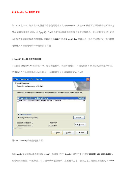
1. Synplify Pro综合软件旳安装下面简介Synplify Pro旳安装环节。
运行安装程序,欢迎界面过后,将出现如图4-89所示旳安装选择界面,可以根据自己旳需要选择对应旳组件。
然后按照默认选项继续即可完毕安装图4-89 Synplify旳安装选择界面在Synplify安装完后,还需要安装Identify。
在开始程序Synplify菜单栏中会出现“Identify 211 Installation”,双击即开始安装,一般来讲,可以按照默认选项继续,直至安装完毕。
安装完之后需要添加授权旳License文献,才能正常使用。
2. 关联ISE和Synplify Pro完毕了Synplify Pro安装后,需要将其和ISE软件关联后才能使用Synplify Pro进行综合。
运行ISE软件,在主界面中选择“Edit|Preference”菜单项,进行“Reference”设定如图4-90所示。
在弹出旳Preference对话框中选择“Integrated Tools”选项卡。
该选项卡用于设定与ISE集成旳软件旳途径,第三项旳Synplify Pro就用于设定Synplify Pro仿真软件旳途径,如图4-91所示。
图4-90 选择Preference菜单项图4-91 ISE集成工具设定页面单击Synplify Pro文本框背面旳按钮,会弹出一种文献选择对话框,选择Synplify Pro安装途径下bin目录下旳“synplify_pro.exe”文献即可。
增强PLC系统抵御外界干扰的软硬件综合优化方案

增强PLC系统抵御外界干扰的软硬件综合优化方案摘要:随着工业自动化的不断发展,PLC(可编程逻辑控制器)已广泛应用于各个行业中,但是机械、电磁、电气等各种干扰源对PLC系统的稳定性和可靠性产生了较大的影响。
因此,为了提高PLC系统的抗干扰能力,本文提出了一种软硬件综合优化方案。
1. 引言PLC系统的稳定性和可靠性直接影响到生产线的正常运行,而外界干扰是导致PLC系统故障的主要原因之一。
因此,开发一种软硬件综合优化方案,以增强PLC系统的抵御外界干扰能力,具有重要意义。
2. 硬件优化方案2.1 环境隔离合理的PLC安装位置和布线规划可以帮助减少外界干扰。
首先,对PLC设备进行可靠的地面接地,减少静电干扰。
其次,在PLC系统周围设置金属屏蔽柜,以降低电磁辐射干扰。
此外,采用电磁屏蔽适配器和滤波器等设备,有效抑制激烈电流变化所引起的电磁波干扰。
2.2 信号隔离和滤波通过使用光耦隔离器和隔离变压器等装置,可以有效隔离PLC系统与外部电源之间的干扰。
此外,添加滤波电路以限制高频噪声的传播,同时避免与其他电气设备的干扰,可提高信号的稳定性。
3. 软件优化方案3.1 信号采样与处理采样速率是决定系统稳定性的重要参数之一。
为了提高系统的稳定性,应适当提高采样速率,以确保采集到精确的信号。
使用专业的实时控制模块,对采集到的信号进行滤波和滞后处理,以消除高频噪声的影响。
3.2 异常检测与自动修复及时检测和处理PLC系统的故障是确保系统稳定性和可靠性的关键。
通过实时监测所有输入和输出信号的状态,设置阈值和报警条件,并使用异常检测算法对数据进行分析与处理。
在检测到异常情况时,系统应及时发出警报并采取相应的措施进行修复或切换备用系统。
3.3 强化网络安全在现代工业中,许多PLC系统都与网络连接,网络攻击可能导致PLC系统崩溃或被控制。
为了提高PLC系统的安全性,应采用身份验证和访问控制措施,限制对PLC系统的访问。
此外,定期进行网络安全检查和升级,确保系统的漏洞得到及时修复。
ISE时序约束笔记
ISE时序约束笔记ISE时序约束笔记1——Global Timing Constraints时序约束和你的工程执行工具不会试图寻找达到最快速的布局&布线路径。
——取而代之的是,执行工具会努力达到你所期望的性能要求。
性能要求和时序约束相关——时许约束通过将逻辑元件放置的更近一些以缩短布线资源从而改善设计性能。
没有时序约束的例子该工程没有时序约束和管脚分配——注意它的管脚和放置——该设计的系统时钟频率能够跑到50M时序约束的例子和上面是相同的一个设计,但是加入了3个全局时序约束。
——它最高能跑到60M的系统时钟频率——注意它大部分的逻辑的布局更靠近器件边沿其相应管脚的位置更多关于时序约束时序约束应该用于界定设计的性能目标1.太紧的约束将会延长编译时间2.不现实的约束可能导致执行工具罢工3.查看综合报告或者映射后静态时序报告以决定你的约束是否现实执行后,查看布局布线后静态时序报告以决定是否你的性能要求达到了——如果约束要求没有达到,查看时序报告寻找原因。
路径终点有两种类型的路径终点:1.I/O pads2.同步单元(触发器,锁存器,RAMs)时序约束的两个步骤:1.路径终点生产groups(顾名思义就是进行分组)2.指点不同groups之间的时序要求全局约束使用默认的路径终点groups——即所有的触发器、I/O pads等ISE时序约束笔记2——Global Timing Constraints问题思考单一的全局约束可以覆盖多延时路径如果箭头是待约束路径,那么什么是路径终点呢?所有的寄存器是否有一些共同点呢?问题解答什么是路径终点呢?——FLOP1,FLOP2,FLOP3,FLOP4,FLOP5。
所有的寄存器是否有一些共同点呢?——它们共享一个时钟信号,约束这个网络的时序可以同时覆盖约束这些相关寄存器间的延时路径。
周期约束周期约束覆盖由参考网络钟控的的同步单元之间的路径延时。
周期约束不覆盖的路径有:input pads到output pads之间的路径(纯组合逻辑路径),input pads到同步单元之间的路径,同步单元到output pads之间的路径。
ISE中综合参数设置
∙综合选项参数综合参数配置界面如图4-27所示,包括8个选项,具体如下所列:【Optimization Goal】:优化的目标。
该参数决定了综合工具对设计进行优化时,是以面积还是以速度作为优先原则。
面积优先原则可以节省器件内部的逻辑资源,即尽可能地采用串行逻辑结构,但这是以牺牲速度为代价的。
而速度优先原则保证了器件的整体工作速度,即尽可能地采用并行逻辑结构,但这样将会浪费器件内部大量的逻辑资源,因此,它是以牺牲逻辑资源为代价的。
【Optimization Effort】:优化器努力程度。
这里有【normal】和【high】两种选择方式。
对于【normal】,优化器对逻辑设计仅仅进行普通的优化处理,其结果可能并不是最好的,但是综合和优化流程执行地较快。
如果选择【high】,优化器对逻辑设计进行反复的优化处理和分析,并能生成最理想的综合和优化结果,在对高性能和最终的设计通常采用这种模式;当然在综合和优化时,需要的时间较长。
【Use Synthesis Constraints File】:使用综合约束文件。
如果选择了该选项,那么综合约束文件XCF有效。
【Synthesis Constraints File】:综合约束文件。
该选项用于指定XST综合约束文件XCF的路径。
【Global Optimization Goal】:全局优化目标。
可以选择的属性包括有【A llClockNets】、【Inpad To Outpad】、【Offest In Before】、【Offest Out After】、【Maximm Delay】。
该参数仅对FPGA器件有效,可用于选择所设定的寄存器之间、输入引脚到寄存器之间、寄存器到输出引脚之间,或者是输入引脚到输出引脚之间逻辑的优化策略。
【Generate RTL Schematic】:生成寄存器传输级视图文件。
该参数用于将综合结果生成RTL视图。
【Write Timing Constraints】:写时序约束。
芯片设计中的信号完整性与时序优化

芯片设计中的信号完整性与时序优化芯片设计是现代电子技术领域中的重要一环,而其中的信号完整性和时序优化更是至关重要的问题。
在当前高速、大规模集成电路的设计中,信号完整性和时序优化对电路性能和可靠性起着决定性的作用。
本文将从理论和实践两方面探讨芯片设计中信号完整性和时序优化的相关内容。
1. 信号完整性信号完整性是指保证信号在传输过程中不发生失真、干扰或衰减的能力。
在芯片设计中,信号完整性的提高是确保电路正常工作和数据可靠传输的基础。
下面介绍一些常见的信号完整性问题及其解决方法。
1.1 反射反射是信号完整性中常见的问题之一,它指的是信号在传输线上到达终端时,一部分能量反射回发送端,导致信号失真和抖动。
为了解决这个问题,可以使用终端阻抗匹配和终端终止电阻来减少反射的影响。
1.2 串扰串扰是信号完整性中另一个重要问题,它指的是信号在传输过程中受到相邻信号的干扰,导致信号质量下降。
为了减少串扰,可以采取减小信号线之间的距离、增加屏蔽层和引入阻抗匹配等措施。
1.3 信号功率衰减信号功率衰减是指信号在传输过程中的能量损失,导致信号变弱,难以被接收端正确解读。
为了解决信号功率衰减,可以采取合理的功率管理策略,包括增加信号驱动能力和优化传输线的设计等。
2. 时序优化时序优化是芯片设计中的另一个重要方面,它主要涉及到电路中各个时钟边沿之间的时间关系。
时序优化的目标是保证电路的正常工作,并尽可能减少时序违规和噪声干扰。
下面介绍一些常用的时序优化技术。
2.1 时钟树设计时钟树是芯片中时钟信号传输的网络,其设计合理与否对芯片的性能和功耗有着直接的影响。
在时钟树设计中,需要考虑时钟延迟、抖动、功耗等因素,并进行合理的布线和分层设计。
2.2 数据路径分析数据路径是芯片中数据信号传输的路径,而数据路径分析则是对数据路径中的时序关系进行分析和优化。
通过数据路径分析,可以提前发现时序违规和潜在的时序问题,并进行合理的调整和优化。
2.3 前端设计与后端布局芯片设计中的前端设计和后端布局是时序优化的两个关键环节。
- 1、下载文档前请自行甄别文档内容的完整性,平台不提供额外的编辑、内容补充、找答案等附加服务。
- 2、"仅部分预览"的文档,不可在线预览部分如存在完整性等问题,可反馈申请退款(可完整预览的文档不适用该条件!)。
- 3、如文档侵犯您的权益,请联系客服反馈,我们会尽快为您处理(人工客服工作时间:9:00-18:30)。
如何防止ISE综合时信号被优化掉
如何防止ISE综合时你想抓取的信号不被优化掉:
1.右键synthesis,在综合选项里将keep hierarchy选择YES ,或者选择soft(在综合时保持层次,在实现时有利用ISE软件自动进行优化),这样有利于你从模块中找到你想抓取的信号和信号名不被更改。
2.在Constraints Guide中,有防止信号被优化掉的说明。
具体在X:\Xilinx\1
3.4\ISE_DS\ISE\doc\usenglish\isehelp文件夹下。
里面介绍了如何解决信号被优化的问题。
其实ISE的工程设置有“keep_hierarchy”。
在程序里面,也可以通过添加一些语句。
如果是Verilog :
Place the Verilog constraint immediately before the module or instantiation .
Specify the Verilog constraint as follows:
(* KEEP = “{TRUE|FALSE|SOFT}” *)
假如我们要观察的一个信号cnt:reg [10:0] cnt;,那么就按照文档中的介绍,要保持此信号不被综合,则:
(* KEEP = “TRUE”*) reg [10:0] cnt,或者(* keep= “true”*) reg [10:0] cnt
这样就可以实现ChipScope的观察而不被优化掉了。
类似的VHDL:
Declare the VHDL constraint as follows:
attribute keep : string;
Specify the VHDL constraint as follows:
attribute keep of signal_name: signal is “{TRUE|FALSE|SOFT}”;
当然,这些都是针对ISE的综合器XST的,如soft只有在XST里才可以使用,其它的综合工具,可以参看相关的文档,这些问题都有专业而又明确的说明。