MAX4456CQH+D中文资料
MAX4460中文资料
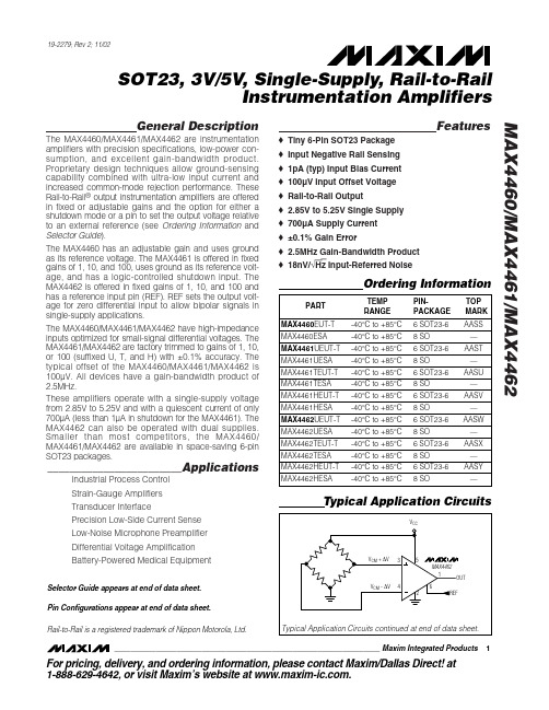
General DescriptionThe MAX4460/MAX4461/MAX4462 are instrumentation amplifiers with precision specifications, low-power con-sumption, and excellent gain-bandwidth product.Proprietary design techniques allow ground-sensing capability combined with ultra-low input current and increased common-mode rejection performance. These Rail-to-Rail ®output instrumentation amplifiers are offered in fixed or adjustable gains and the option for either a shutdown mode or a pin to set the output voltage relative to an external reference (see Ordering Information and Selector Guide ).The MAX4460 has an adjustable gain and uses ground as its reference voltage. The MAX4461 is offered in fixed gains of 1, 10, and 100, uses ground as its reference volt-age, and has a logic-controlled shutdown input. The MAX4462 is offered in fixed gains of 1, 10, and 100 and has a reference input pin (REF). REF sets the output volt-age for zero differential input to allow bipolar signals in single-supply applications.The MAX4460/MAX4461/MAX4462 have high-impedance inputs optimized for small-signal differential voltages. The MAX4461/MAX4462 are factory trimmed to gains of 1, 10,or 100 (suffixed U, T, and H) with ±0.1% accuracy. The typical offset of the MAX4460/MAX4461/MAX4462 is 100µV. All devices have a gain-bandwidth product of 2.5MHz.These amplifiers operate with a single-supply voltage from 2.85V to 5.25V and with a quiescent current of only 700µA (less than 1µA in shutdown for the MAX4461). The MAX4462 can also be operated with dual supplies.Smaller than most competitors, the MAX4460/MAX4461/MAX4462 are available in space-saving 6-pin SOT23 packages.________________________ApplicationsIndustrial Process Control Strain-Gauge Amplifiers Transducer InterfacePrecision Low-Side Current Sense Low-Noise Microphone Preamplifier Differential Voltage Amplification Battery-Powered Medical EquipmentFeatureso Tiny 6-Pin SOT23 Package o Input Negative Rail Sensing o 1pA (typ) Input Bias Current o 100µV Input Offset Voltage o Rail-to-Rail Outputo 2.85V to 5.25V Single Supply o 700µA Supply Current o ±0.1% Gain Erroro 2.5MHz Gain-Bandwidth Product o 18nV/√Hz Input-Referred NoiseMAX4460/MAX4461/MAX4462SOT23, 3V/5V , Single-Supply, Rail-to-RailInstrumentation Amplifiers________________________________________________________________Maxim Integrated Products119-2279; Rev 2; 11/02For pricing, delivery, and ordering information,please contact Maxim/Dallas Direct!at 1-888-629-4642, or visit Maxim’s website at .Ordering InformationRail-to-Rail is a registered trademark of Nippon Motorola, Ltd.Pin Configurations appear at end of data sheet.Typical Application CircuitsSelector Guide appears at end of data sheet.M A X 4460/M A X 4461/M A X 4462SOT23, 3V/5V , Single-Supply, Rail-to-Rail Instrumentation Amplifiers 2_______________________________________________________________________________________ABSOLUTE MAXIMUM RATINGSStresses beyond those listed under “Absolute Maximum Ratings” may cause permanent damage to the device. These are stress ratings only, and functional operation of the device at these or any other conditions beyond those indicated in the operational sections of the specifications is not implied. Exposure to absolute maximum rating conditions for extended periods may affect device reliability.Supply Voltage (V DD to V SS ) ...................................-0.3V to +6V All Other Pins...................................(V SS - 0.3V) to (V DD + 0.3V)Output Short-Circuit Duration to Either Supply.........................1s Continuous Power Dissipation (T A = +70°C)6-Pin SOT23 (derate 8.7mW/°C above +70°C)............695mW 8-Pin SO (derate 5.9mW/°C above +70°C)..................470mWOperating Temperature Range ...........................-40°C to +85°C Junction Temperature......................................................+150°C Storage Temperature Range.............................-65°C to +150°C Lead Temperature (soldering, 10s)....................................300°CELECTRICAL CHARACTERISTICS—MAX4460/MAX4461(V DD = 5V, V CM = 0V, V DIFF = V IN+- V IN-= 50mV to 100mV for G = 1, 20mV to 100mV for G = 10, 2mV to 48mV for G =100,MAX4460 is configured for G = 10, R L = 200k Ωto GND, T A = +25°C , unless otherwise noted.)MAX4460/MAX4461/MAX4462SOT23, 3V/5V , Single-Supply, Rail-to-RailInstrumentation AmplifiersELECTRICAL CHARACTERISTICS —MAX4460/MAX4461 (continued)ELECTRICAL CHARACTERISTICS —MAX4460/MAX4461M A X 4460/M A X 4461/M A X 4462SOT23, 3V/5V , Single-Supply, Rail-to-Rail Instrumentation Amplifiers 4_______________________________________________________________________________________ELECTRICAL CHARACTERISTICS —MAX4460/MAX4461 (continued)(V DD = 5V, V CM = 0V, V DIFF = V IN+- V IN-= 50mV to 100mV for G = 1, 20mV to 100mV for G = 10, 2mV to 48mV for G = 100,MAX4460 is configured for G = 10, R L = 200k Ωto GND, T A = T MIN to T MAX , unless otherwise noted.)MAX4460/MAX4461/MAX4462SOT23, 3V/5V , Single-Supply, Rail-to-RailInstrumentation Amplifiers_______________________________________________________________________________________5ELECTRICAL CHARACTERISTICS —MAX4462(V DD = 5V, V SS = 0V, V CM = V REF = V DD /2, R L = 100k Ωto V DD /2, T A = +25°C , unless otherwise noted. V DIFF = V IN+- V IN-= -100mVM A X 4460/M A X 4461/M A X 4462SOT23, 3V/5V , Single-Supply, Rail-to-Rail Instrumentation Amplifiers 6_______________________________________________________________________________________ELECTRICAL CHARACTERISTICS —MAX4462 (continued)ELECTRICAL CHARACTERISTICS —MAX4462MAX4460/MAX4461/MAX4462SOT23, 3V/5V , Single-Supply, Rail-to-RailInstrumentation Amplifiers_______________________________________________________________________________________7ELECTRICAL CHARACTERISTICS —MAX4462 (continued)Specifications section).Note 2:Guaranteed by design, not production tested.Note 3:Output swing high is measured only on G = 100 devices. Devices with G = 1 and G = 10 have output swing high limited bythe range of V REF , V CM , and V DIFF (see Output Swing section).Note 4:Short-circuit duration limited to 1s (see Absolute Maximum Ratings).Note 5:SOT23 units are 100% production tested at +25°C. Limits over temperature are guaranteed by design.M A X 4460/M A X 4461/M A X 4462SOT23, 3V/5V , Single-Supply, Rail-to-Rail Instrumentation Amplifiers 8_______________________________________________________________________________________Typical Operating Characteristics(V DD = 5V, V SS = 0V, V IN + = V IN-= V REF = V DD /2, R L = 100k Ωto V DD /2, T A = +25°C, unless otherwise noted. V DIFF = V IN+- V IN-= -100mV to +100mV for G = 1 and G = 10, -20mV to +20mV for G = 100.)10,00010001001010.11001101k10k100kINPUT VOLTAGE NOISE vs. FREQUENCYM A X 4460 t o c 07FREQUENCY (Hz)I N P U T V O L T A G E N O I S E (n V /H z )PEAK-TO-PEAK NOISE (0.1Hz TO 10Hz)1s/div2µV/divINPUT REFERRED G = 1, 10, OR 1000.0100.0050.0150.0200.0250.0300.0350.0400.045101001k 10k100kTOTAL HARMONIC DISTORTION PLUS NOISE vs. FREQUENCYFREQUENCY (Hz)T H D + N (%)042108612141618-300-200-150-250-100-5050100150200250300VOLTAGE OFFSET HISTOGRAMVOLTAGE OFFSET (µV)P E R C E N T A G E O F U N I T S42612141081600.020.030.040.050.010.060.070.080.090.10GAIN-LINEARITY HISTOGRAMLINEARITY (%)P E R C E N T A G E O F U N I T S426121410816-5-3-2-10-412345VOLTAGE OFFSET DRIFT HISTOGRAMVOLTAGE OFFSET DRIFT (µV/°C)P E R C E N T A G E O F U N I T S42861012-0.50GAIN ERROR HISTOGRAMGAIN ERROR (%)P E R C E N T A G E O F U N I TS-0.4-0.2-0.10.10.20.30.40.5-0.3-130-120-90-100-110-80-70-60-50-40-30-200.11011001k10kCOMMON-MODE REJECTION RATIOvs. FREQUENCYFREQUENCY (Hz)C M R R (d B )POWER-SUPPLY REJECTION RATIOVS. FREQUENCYFREQUENCY (Hz)0.01101001k 0.1110kP S R R (d B )-120-100-80-60-20-40MAX4460/MAX4461/MAX4462SOT23, 3V/5V , Single-Supply, Rail-to-RailInstrumentation Amplifiers_______________________________________________________________________________________930065040080075070090095085010002.75 3.503.753.003.25 4.004.254.504.755.00SUPPLY CURRENTVS. SUPPLY VOLTAGESUPPLY VOLTAGE (V)S U P P L Y C U R R E N T (µA )60055050045035004286121014SHUTDOWN CURRENT VS. SUPPLY VOLTAGESUPPLY VOLTAGE (V)S U P P L Y C U R R E N T (n A )2.753.503.753.003.254.004.254.504.755.0000.040.020.080.060.120.100.140.180.160.200.20.30.40.10.50.60.70.90.8 1.0MAX4462HNORMALIZED OUTPUT ERROR vs. COMMON-MODE VOLTAGEV CM (V)N O R M A L I Z E D O U T P U T E R R O R (%)-0.30-0.16-0.18-0.20-0.22-0.24-0.26-0.28-0.12-0.14-0.08-0.10-0.06-0.02-0.040-2.7-2.1-1.8-2.4-1.5-1.2-0.9-0.60-0.3MAX4462HNORMALIZED OUTPUT ERROR vs. COMMON-MODE VOLTAGEV CM (V)N O R M A L I Z E D O U T P U T E R R O R (%)040208060120100140180160200023415679810OUTPUT SWING HIGHVS. OUTPUT CURRENTOUTPUT CURRENT (mA)V D D - V O U T (m V )10050200150300250350450400500023*********OUTPUT SWING LOW vs. OUTPUT CURRENTOUTPUT CURRENT (mA)V O U T - V S S (m V )Typical Operating Characteristics (continued)(V DD = 5V, V SS = 0V, V IN + = V IN-= V REF = V DD /2, R L = 100k Ωto V DD /2, T A = +25°C, unless otherwise noted. V DIFF = V IN+- V IN-= -100mV to +100mV for G = 1 and G = 10, -20mV to +20mV for G = 100.)-1010030204050GAIN vs. FREQUENCYFREQUENCY (Hz)G A I N (d B)0.011100.11001k10k 222325242627-4010-15356085GAIN BANDWIDTH vs. TEMPERATURETEMPERATURE (°C)-3d B B A N D W I D T H (k H z )SETTLING TIME (GAIN = 100)MAX4460 toc1840µs/divINPUT 10mV/divOUTPUT 500mV/divOUTPUT 10mV/divM A X 4460/M A X 4461/M A X 4462SOT23, 3V/5V , Single-Supply, Rail-to-Rail Instrumentation Amplifiers 10______________________________________________________________________________________Typical Operating Characteristics (continued)(V DD = 5V, V SS = 0V, V IN + = V IN-= V REF = V DD /2, R L = 100k Ωto V DD /2, T A = +25°C, unless otherwise noted. V DIFF = V IN+- V IN-= -100mV to +100mV for G = 1 and G = 10, -20mV to +20mV for G = 100.)LARGE-SIGNAL PULSE RESPONSE(GAIN = 1V/V)MAX4460 toc19INPUTOUTPUT50mV/div1µs/div LARGE-SIGNAL PULSE RESPONSE(GAIN = 100V/V)MAX4460 toc20INPUT 10mV/divOUTPUT 1V/div20µs/divSMALL-SIGNAL PULSE RESPONSE(GAIN = 1V/V)MAX4460 toc21INPUTOUTPUT10mV/div1µs/divSMALL-SIGNAL PULSE RESPONSE(GAIN = 1V/V)1µs/divINPUT 10mV/divOUTPUTC L = 100pFSMALL-SIGNAL PULSE RESPONSE(GAIN = 100V/V)MAX4460 toc23INPUT 1mV/div OUTPUT 100mV/div20µs/divSMALL-SIGNAL PULSE RESPONSE(GAIN = 100V/V)X 4460 t o c 2420µs/divINPUT 1mV/divOUTPUT 100mV/divGAIN = +100V/V C L = 100pFC L = 100pFMAX4460/MAX4461/MAX4462SOT23, 3V/5V , Single-Supply, Rail-to-RailInstrumentation Amplifiers______________________________________________________________________________________11Pin DescriptionsM A X 4460/M A X 4461/M A X 4462SOT23, 3V/5V , Single-Supply, Rail-to-Rail Instrumentation Amplifiers 12______________________________________________________________________________________Detailed DescriptionThe MAX4460/MAX4461/MAX4462 family of instrumen-tation amplifiers implements Maxim ’s proprietary indi-rect current-feedback design to achieve a precision specification and excellent gain-bandwidth product.These new techniques allow ground-sensing capability combined with an ultra-low input current and an increased common-mode rejection.The differential input signal is converted to a current by an input transconductance stage. An output transcon-ductance stage converts a portion of the output voltage (equal to the output voltage divided by the gain) into another precision current. These two currents are sub-tracted and the result is fed to a loop amplifier with a class AB output stage with sufficient gain to minimize errors (Figure 1).The MAX4461U/T/H and MAX4462U/T/H have factory-trimmed gains of 1, 10, and 100, respectively. The MAX4460 has an adjustable gain, set with an external pair of resistors between pins OUT, FB, and GND (Figure 2).The MAX4462U/T/H has a reference input (REF) which is connected to an external reference for bipolar opera-tion of the device. The range for V REF is 0.1V to (V DD -1.7V). For full output-swing capability, optimal perfor-mance is usually obtained with V REF = V DD /2.The MAX4460/MAX4461/MAX4462 operate with single-supply voltages of 2.85V to 5.25V. It is possible to use the MAX4462U/T/H in a dual-supply configuration with up to ±2.6V at V DD and V SS , with REF connected to ground.The MAX4461U/T/H has a shutdown feature to reduce the supply current to less than 1µA. The MAX4461U/T/H output is internally referenced to ground, making the part suitable for unipolar operations.The MAX4460 has an FB pin that can be used to exter-nally set the gain through a pair of resistors (see Setting the Gain (MAX4460) section). The MAX4460 output is internally referenced to ground, making the part suitable for unipolar operations.Figure 1. Functional DiagramsFigure 2. MAX4460 External Resistor ConfigurationFunctional DiagramsMAX4460/MAX4461/MAX4462SOT23, 3V/5V , Single-Supply, Rail-to-RailInstrumentation Amplifiers______________________________________________________________________________________13Input Common-Mode and OutputReference RangesMAX4460/MAX4461/MAX4462 have an input common-mode range of 100mV below the negative supply to 1.7V below the positive supply.The output reference voltage of MAX4462U/T/H is set by REF and ranges from 100mV above the negative supply to 1.7V below the positive supply. For maximum voltage swing in a bipolar operation, connect REF to V DD /2. The output voltages of the MAX4460 and MAX4461U/T/H are referenced to ground. Unlike the traditional three-op-amp configuration of common instrumentation amplifiers, the MAX4460/MAX4461/MAX4462 have ground-sensing capability (or to V SS in dual-supply configuration) in addition to the extremely high input impedances of MOS input differential pairs.Input Differential Signal RangeThe MAX4460/MAX4461/MAX4462 feature a proprietary input structure optimized for small differential signals.The unipolar output of the MAX4460/MAX4461 is nomi-nally zero-for-zero differential input. However, these devices are specified for inputs of 50mV to 100mV for the unity-gain devices, 20mV to 100mV for gain of 10devices, and 2mV to 48mV for gain of 100 devices. The MAX4460/MAX4461 can be used with differential inputs approaching zero, albeit with reduced accuracy.The bipolar output of the MAX4462 allows bipolar input ranges. The output voltage is equal to the reference voltage for zero differential input. The MAX4462 is specified for inputs of ±100mV for the unity gain and gain of 10 devices, and ±20mV for gain of 100 devices.The gain of 100 devices (MAX4462H) can be operated beyond 20mV signal provided the reference is chosen for unsymmetrical swing.Output SwingThe MAX4460/MAX4461/MAX4462 are designed to have rail-to-rail output voltage swings. However,depending on the selected gain and supply voltage (and output reference level of the MAX4462), the rail-to-rail output swing is not required.For example, consider the MAX4461U, a unity-gain device with its ground pin as the output reference level.The input voltage range is 0 to 100mV (50mV minimum to meet accuracy specifications). Because the device is unity gain and the output reference level is ground,the output only sees excursions from ground to 100mV.Devices with higher gain and with bipolar output such as the MAX4462, can be configured to swing to higherlevels. In these cases, as the output approaches either supply, accuracy may degrade, especially under heavy output loading.Shutdown ModeThe MAX4461U/T/H features a low-power shutdown mode. When the SHDN pin is pulled low, the internal transconductance and amplifier blocks are switched off and supply current drops to typically less than 0.1µA (Figure 1).I n shutdown, the amplifier output is high impedance.The output transistors are turned off, but the feedback resistor network remains connected. If the external load is referenced to GND, the output drops to approximate-ly GND in shutdown. The output impedance in shut-down is typically greater than 100k Ω. Drive SHDN high or connect to V CC for normal operation.A User Guide to Instrumentation Amplifier Accuracy SpecificationsAs with any other electronic component, a complete understanding of instrumentation amplifier specifica-tions is essential to successfully employ these devices in their application circuits. Most of the specifications for these differential closed-loop gain blocks are similar to the well-known specifications of operational ampli-fiers. However, there are a few accuracy specifications that could be confusing to first-time users. Therefore,some explanations and examples may be helpful.Accuracy specifications are measurements of close-ness of an actual output response to its ideal expected value. There are three main specifications in this category:G Gain errorG Gain nonlinearity errorGOffset errorIn order to understand these terms, we must look at the transfer function of an ideal instrumentation amplifier. As expected, this must be a straight line passing through origin with a slope equal to the ideal gain (Figure 3). I f the ideal gain is equal to 10 and the extreme applied input voltages are -100mV and +100mV, then the value of the output voltages are -1V and +1V, respectively.Note that the line passes through the origin and therefore a zero input voltage gives a zero output response.The transfer function of a real instrumentation amplifier is quite different from the ideal line pictured in Figure 3.Rather, it is a curve such as the one indicated as the typical curve in Figure 4, connecting end points A and B.M A X 4460/M A X 4461/M A X 4462SOT23, 3V/5V , Single-Supply, Rail-to-Rail Instrumentation Amplifiers 14______________________________________________________________________________________Looking at this curve, one can immediately identify three types of errors.First, there is an obvious nonlinearity (curvature) when this transfer function is compared to a straight line.More deviation is measured as greater nonlinearity error. This is explained in more detail below.Second, even if there was no nonlinearity error, i.e., the actual curve in Figure 4 was a straight line connecting end points A and B, there exists an obvious slope devi-ation from that of an ideal gain slope (drawn as the “ideal ” line in Figure 4). This rotational error (delta slope) is a measure of how different the actual gain (G A ) is from the expected ideal gain (G I)and is called gain error (GE) (see the equation below).Third, even if the actual curve between points A and B was a straight line (no nonlinearity error) and had the same slope as the ideal gain line (no gain error), there is still another error called the end-point offset error (OE on vertical axis), since the line is not passing through the origin.Figure 5 is the same as Figure 4, but the ideal line (CD)is shifted up to pass through point E (the Y intercept of end-points line AB).This is done to better visualize the rotational error (GE),which is the difference between the slopes of end points line AB and the shifted ideal line CD. Mathematically:GE (%) = 100 x (G A - G I ) / G IFigure 5. Typical Transfer Function for a Real Instrumentation Amplifier (Ideal Line (CD) Is Shifted by the End-Points Offset (OE) to Visualize Gain Error)MAX4460/MAX4461/MAX4462SOT23, 3V/5V , Single-Supply, Rail-to-RailInstrumentation Amplifiers______________________________________________________________________________________15The rotational nature of gain error, and the fact that it is pivoted around point E in Figure 5, shows that gain-error contribution to the total output voltage error is directly proportional to the input voltage. At zero input voltage, the error contribution of gain error is zero, i.e.,the total deviation from the origin (the expected zero output value) is only due to end-points OE and nonlin-earity error at zero value of input (segment EZ on the vertical axis).The nonlinearity is the maximum deviation from a straight line, and the end-point nonlinearity is the devia-tion from the end-point line. As shown in Figure 5, it is likely that two nonlinearities are encountered, one posi-tive and the other a negative nonlinearity error, shown as NL+ and NL- in Figure 5.Generally, NL+ and NL- have different values and this remains the case if the device is calibrated (trimmed)for end-points errors (which means changing the gain of the instrumentation amplifier in such a way that the slope of line AB becomes equal to that of CD, and the offset becomes trimmed such that OE vanishes to zero). This is an undesirable situation when nonlinearity is of prime interest.The straight line shown in Figure 6 is in parallel to end-points line AB and has a Y intercept of OS on the verti-cal axis. This line is a shifted end-points line such that the positive and negative nonlinearity errors with respect to this line are equal. For this reason, the line is called the best straight line (BSL). Maxim internally trims the MAX4460/MAX4461/MAX4462 with respect to this line (changing the gain slope to be as close as possible to the slope of the ideal line and trimming the offset such that OS gets as close to the origin as possi-ble) to minimize all the errors. The total accuracy error is still the summation of the gain error, nonlinearity, and offset errors.As an example, assume the following specification for an instrumentation amplifier:Gain = 10GE = 0.15%Offset (BSL) = 250µV NL = 0.05%V DIF (input) = -100mV to +100mVWhat is the maximum total error associated with the GE, offset (BSL), and NL? With a differential input range of -0.1V to +0.1V and a gain of 10, the output voltage assumes a range of -1V to +1V, i.e., a total full-scale range of 2V.The individual errors are as follows:GE = (0.15%) (10) (100mV) = 1.5mV Offset (BSL) = (250µV) (10) = 2.5mVNL = (0.05%) (2V) = 1mVMaximum Total Error = 1.5mV + 2.5mV + 1mV= 5mVSo, the absolute value of the output voltage, consider-ing the above errors, would be at worst case between 0.995V to 1.005V. Note that other important parameters such as PSRR, CMRR, and noise also contribute to the total error in instrumentation applications. They are not considered here.Figure 6. To Minimize Nonlinearity Error, the MAX4460/MAX4461/MAX4462 are Internally Trimmed to Adjust Gain and Offset for the Best Straight Line so NL- = NL+M A X 4460/M A X 4461/M A X 4462SOT23, 3V/5V , Single-Supply, Rail-to-Rail Instrumentation Amplifiers 16______________________________________________________________________________________Applications InformationSetting the Gain (MAX4460)The MAX4460 gain is set by connecting a resistive-divider from OUT to GND, with the center tap connect-ed to FB (Figure 2). The gain is calculated by:Gain = 1 + R2 / R1Because FB has less than 100pA IB, high-valued resis-tors can be used without significantly affecting the gain accuracy. The sum of resistors (R1 + R2) near 100k Ωis a good compromise. Resistor accuracy directly affects gain accuracy. Resistor sum less than 20k Ωshould not be used because their loading can slightly affect output accuracy.Capacitive-Load StabilityThe MAX4460/MAX4461/MAX4462 are capable of dri-ving capacitive loads up to 100pF.Applications needing higher capacitive drive capability may use an isolation resistor between OUT and the load to reduce ringing on the output signal. However this reduces the gain accuracy due to the voltage drop across the isolation resistor.Output LoadingFor best performance, the output loading should be to the potential seen at REF for the MAX4462 or to ground for the MAX4460/MAX4461.REF Input (MAX4462)The REF input of the MAX4462 can be connected to any voltage from (V SS + 0.1V) to (V DD - 1.7V). A buffered voltage-divider with sink and source capability works well to center the output swing at V DD /2. Unbuffered resistive dividers should be avoided because the 100k Ω(typ) input impedance of REF causes amplitude-depen-dent variations in the divider ’s output.Bandgap references, either series or shunt, can be used to drive REF. This provides a voltage and temper-ature invariant reference. This same reference voltage can be used to bias bridge sensors to eliminate supply voltage ratiometricity. For proper operation, the refer-ence must be able to sink and source at least 25µA.I n many applications, the MAX4462 is connected to a CODEC or other device with a reference voltage out-put. In this case, the receiving device ’s reference out-put makes an ideal reference voltage. Verify the reference output of the device is capable of driving the MAX4462’s REF input.Power-Supply Bypass and LayoutGood layout technique optimizes performance by decreasing the amount of stray capacitance at the instrumentation amplifier ’s gain-setting pins. Excess capacitance produces peaking in the amplifier ’s fre-quency response. To decrease stray capacitance, min-imize trace lengths by placing external components as close to the instrumentation amplifier as possible. For best performance, bypass each power supply to ground with a separate 0.1µF capacitor.Microphone AmplifierThe MAX4462’s bipolar output, along with its excellent common-mode rejection ratio, makes it suitable for pre-cision microphone amplifier applications. Figure 7 illus-trates one such circuit. I n this case, the electret microphone is resistively biased to the supply voltage through a 2.2k Ωpullup resistor. The MAX4462 directly senses the output voltage at its noninverting input, and indirectly senses the microphone ’s ground through an AC-coupling capacitor. This technique provides excel-lent rejection of common-mode noise picked up by the microphone lead wires. Furthermore, ground noise from distantly located microphones is reduced.The single-ended output of the MAX4462 is converted to differential through a single op amp, the MAX4335. The op amp forces the midpoint between OUT+ and OUT- to be equal to the reference voltage. The configuration does not change the MAX4662T ’s fixed gain of 10.MAX4460/MAX4461/MAX4462SOT23, 3V/5V , Single-Supply, Rail-to-RailInstrumentation Amplifiers______________________________________________________________________________________17Figure 7. Differential I/O Microphone AmplifierChip InformationTRANSISTOR COUNT: 421PROCESS: BiCMOSTypical Application Circuits(continued)M A X 4460/M A X 4461/M A X 4462SOT23, 3V/5V , Single-Supply, Rail-to-Rail Instrumentation Amplifiers 18______________________________________________________________________________________Pin Configurations。
AO4456中文资料
SymbolTyp Max 31405975R θJL 1624Maximum Junction-to-AmbientASteady-State °C/W Maximum Junction-to-LeadCSteady-State°C/WThermal Characteristics ParameterUnits Maximum Junction-to-Ambient At ≤ 10s R θJA °C/W AO4456AO4456SymbolMin TypMaxUnits BV DSS 30V V DS =24V, V GS =0V0.0080.1T J =125°C920I GSS 0.1µA V GS(th)Gate Threshold Voltage 1.4 1.82.4V I D(ON)120A 3.8 4.6T J =125°C5.97.44.5 5.6m Ωg FS 112S V SD0.370.5V I S 5A C iss 64307716pF C oss 756pF C rss 352pFR g0.9 1.4ΩQ g (10V)96115Q g (4.5V)4453nC Q gs 17nC Q gd 13nC t D(on)17.5ns t r 10ns t D(off)56ns t f 10.5nst rr 2025ns Q rr26nC THIS PRODUCT HAS BEEN DESIGNED AND QUALIFIED FOR THE CONSUMER MARKET. APPLICATIONS OR USES AS CRITICAL COMPONENTS IN LIFE SUPPORT DEVICES OR SYSTEMS ARE NOT AUTHORIZED. AOS DOES NOT ASSUME ANY LIABILITY ARISING OUT OF SUCH APPLICATIONS OR USES OF ITS PRODUCTS. AOS RESERVES THE RIGHT TO IMPROVE PRODUCT DESIGN,FUNCTIONS AND RELIABILITY WITHOUT NOTICE.Total Gate Charge VGS=10V, VDS=15V, ID=20AGate Drain Charge V GS =0V, V DS =15V, f=1MHzSWITCHING PARAMETERS Total Gate Charge Gate Source Charge Gate resistanceV GS =0V, V DS =0V, f=1MHzTurn-On Rise Time Turn-Off DelayTime V GS =10V, V DS =15V, R L =0.75Ω,R GEN =3ΩTurn-Off Fall TimeTurn-On DelayTime m ΩV GS =4.5V, I D =20AI S =1A,V GS =0V V DS =5V, I D =20A Maximum Body-Diode + Schottky Continuous Current Input Capacitance Output Capacitance DYNAMIC PARAMETERSR DS(ON)Static Drain-Source On-ResistanceForward TransconductanceDiode Forward VoltageV DS =V GS I D =250µA Electrical Characteristics (T J =25°C unless otherwise noted)STATIC PARAMETERS Parameter Conditions I DSS Zero Gate Voltage Drain Current mA V DS =0V, V GS = ±12V Gate-Body leakage current Body Diode Reverse Recovery Time Body Diode Reverse Recovery ChargeI F =20A, dI/dt=300A/µsDrain-Source Breakdown Voltage On state drain currentI D =1mA, V GS =0V V GS =10V, V DS =5V V GS =10V, I D =20AReverse Transfer Capacitance I F =20A, dI/dt=300A/µs A: The value of R θJA is measured with the device in a still air environment with T A =25°C. The power dissipation P DSM and current rating I DSM are based on TJ(MAX)=150°C, using t ≤ 10s junction-to-ambient thermal resistance.B: Repetitive rating, pulse width limited by junction temperature TJ(MAX)=150°C.C. The R θJA is the sum of the thermal impedence from junction to lead R qJL and lead to ambient.D. The static characteristics in Figures 1 to 6 are obtained using <300 ms pulses, duty cycle 0.5% max.E. These tests are performed with the device mounted on 1 in 2 FR-4 board with 2oz. Copper, in a still air environment with T A=25°C. The SOA curve provides a single pulse rating. Rev 1: June 2006AO4456AO4456AO4456。
MAX4466EXK中文资料

5-Pin SC70 (derate 2.5mW/°C above +70°C) .............200mW 5-Pin SOT23 (derate 7.1mW/°C above +70°C) ...........571mW
ELECTRICAL CHARACTERISTICS
(VCC = +5V, VCM = 0, VOUT = VCC/2, RL = ∞ to VCC/2, SHDN = GND (MAX4467/MAX4468 only). TA = TMIN to TMAX, unless otherwise noted. Typical values specified at TA = +25°C.) (Note 1)
TOP VIEW
IN+ 1
5 VCC
MAX4465 GND 2 MAX4466
IN- 3
4 OUT
SC70/SOT23 Pin Configurations continued at end of data sheet.
Rail-to-Rail is a registered trademark of Nippon Motorola, Ltd.
Features
o +2.4V to +5.5V Supply Voltage Operation
o Versions with 5nA Complete Shutdown Available (MAX4467/MAX4468)
CDRH64NP-1OOMB中文资料

仕 様 書形 名CDRH641.外形1-1.寸法図(mm)1-2.捺印表示例 1-3.推奨ランド寸法 (mm)2.コイル仕様 2-1.端子接続図(裏面図)電極(端子)間の隙間はシルク処理をして御使用下さい。
頭部直捺印捺印位置不定compliance Cd:Max.0.01wt%others:Max.0.1wt%RoHS1仕 様 書 形 名CDRH642-2.電気的特性Ⅰ(リール の場合)NO. 品 名 表示 インダクタンス[以内]※1D.C.R.(Ω)[以下](at 20℃)※2定格電流(A)※3スミダコード0102 CDRH64NP-1ØØMCCDRH64NP-12ØMC10012010 μH ± 20%12 μH ± 20%0.11(84m)0.13(96m)1.681.514732-00134732-00150304 CDRH64NP-15ØMCCDRH64NP-18ØMC15018015 μH ± 20%18 μH ± 20%0.14(0.11)0.16(0.12)1.321.184732-00164732-00170506 CDRH64NP-22ØMCCDRH64NP-27ØMC22027022 μH ± 20%27 μH ± 20%0.21(0.16)0.29(0.23)1.060.954732-00184732-00190708 CDRH64NP-33ØMCCDRH64NP-39ØMC33039033 μH ± 20%39 μH ± 20%0.33(0.25)0.35(0.27)0.880.774732-00204732-00210910 CDRH64NP-47ØMCCDRH64NP-56ØMC47056047 μH ± 20%56 μH ± 20%0.39(0.30)0.43(0.34)0.760.674732-00224732-00231112 CDRH64NP-68ØMCCDRH64NP-82ØMC68082068 μH ± 20%82 μH ± 20%0.59(0.46)0.66(0.51)0.600.574732-00244732-00261314 CDRH64NP-1Ø1MCCDRH64NP-121MC101121100μH ± 20%120μH ± 20%0.76(0.58)0.83(0.64)0.500.474732-00274732-00281516 CDRH64NP-151MCCDRH64NP-181MC151181150μH ± 20%180μH ± 20%1.24(0.96)1.89(1.51)0.420.374732-00294732-00301718 CDRH64NP-221MCCDRH64NP-271MC221271220μH ± 20%270μH ± 20%2.10(1.68)2.37(1.90)0.340.314732-00314732-00321920 CDRH64NP-331MCCDRH64NP-391MC331391330μH ± 20%390μH ± 20%2.66(2.13)2.94(2.35)0.270.264732-00334732-00342122 CDRH64NP-471MCCDRH64NP-561MC471561470μH ± 20%560μH ± 20%3.89(3.11)5.25(4.20)0.240.214732-00354732-00372324 CDRH64NP-681MCCDRH64NP-821MC681821680μH ± 20%820μH ± 20%5.97(4.78)6.54(5.23)0.180.174732-00384732-003925 CDRH64NP-1Ø2MC 102 1.0 mH ± 20% 8.94(7.15) 0.16 4732-0040※1: 測定周波数 L at 1 kHz※2: ( )内は、標準値とする。
W25Q64中文资料精编版
W25Q64BV出版日期:2010年7月8日- 1 - 版本E64M位与串行闪存双路和四路SPIW25Q64BV- 2 -目录1,一般DESCRIPTION (5)2。
FEATURES (5)3引脚配置SOIC208-MIL.......................................... .. (6)4,焊垫配置WSON8X6-MM.......................................... . (6)5,焊垫配置PDIP300-MIL.......................................... . (7)6引脚说明SOIC208密耳,PDIP300密耳和WSON8X6-MM................................ 7......7引脚配置SOIC300mil的.......................................... .. (8)8引脚SOIC封装说明300-MIL (8)8.1包装Types (9)8.2片选(/CS) (9)8.3串行数据输入,输出和IO(DI,DO和IO0,IO1,IO2,IO3)............................. 9.......8.4写保护(/WP) (9)8.5控股(/HOLD) (9)8.6串行时钟(CLK) (9)9座DIAGRAM (10)10功能DESCRIPTION (11)10.1 SPI OPERATIONS (11)10.1.1标准SPI Instructions (11)10.1.2双SPI Instructions (11)10.1.3四路SPI Instructions (11)10.1.4保持功能 (11)10.2写保护 (12)10.2.1写保护Features (12)11,控制和状态寄存器............................................ .. (13)11.1状态REGISTER (13)11.1.1 BUSY (13)11.1.2写使能锁存(WEL) (13)11.1.3块保护位(BP2,BP1,BP0)..................................... .. (13)11.1.4顶/底块保护(TB)....................................... .................................................. ..1311.1.5部门/块保护(SEC) (13)11.1.6状态寄存器保护(SRP,SRP0)....................................... . (14)11.1.7四路启用(QE) (14)11.1.8状态寄存器内存保护........................................... .. (16)11.2 INSTRUCTIONS (17)11.2.1制造商和设备标识........................................... .. (17)11.2.2指令集表1 (18)W25Q64BV11.2.3指令表2(阅读说明书)....................................... (19)出版日期:2010年7月8日- 3 - 修订版E11.2.4写使能(06h) (20)11.2.5写禁止(04h) (20)11.2.6读状态寄存器1(05H)和读状态寄存器2(35H).............................. (21)11.2.7写状态寄存器(01H)......................................... .................................................. .. (22)11.2.8读取数据(03h) (23)11.2.9快速阅读(0Bh) (24)11.2.10快速读双输出(3BH)........................................ .................................................. 0.25 11.2.11快速读四路输出(6BH)........................................ .. (26)11.2.12快速读双I / O (BBh) (27)11.2.13快速读取四I/ O (EBh) (29)11.2.14八进制字读取四I/ O(E3H)..................................... (31)11.2.15页编程(02h) (33)11.2.16四路输入页编程(32H)........................................ . (34)11.2.17扇区擦除(20H) (35)11.2.1832KB的块擦除(52H) (36)11.2.1964KB的块擦除(D8h) (37)20年2月11日芯片擦除(C7H/ 60h) (38)21年2月11日擦除挂起(75h) (39)22年2月11日擦除恢复(7Ah) (40)23年11月2日掉电(B9h) (41)24年2月11日高性能模式(A3H)......................................... (42)25年2月11日发布掉电或高性能模式/设备ID(ABH) (42)26年2月11日读制造商/设备ID(90H)....................................... . (44)27年2月11日阅读唯一的ID号(4BH)........................................ . (45)28年2月11日读JEDEC的ID (9Fh) (46)29年2月11日连续读取模式复位(FFH或FFFFH)...................................... .. (47)12,电气特性.............................................. (48)12.1绝对最大Ratings (48)12.2操作范围 (48)12.3上电时序和写抑制阈值......................................... (49)12.4直流电气Characteristics (50)12.5 AC测量条件.............................................. .. (51)12.6 AC电气Characteristics (52)12.7 AC电气特性(续)......................................... . (53)12.8串行输出Timing (54)12.9输入Timing (54)12.10持有Timing (54)13包装SPECIFICATION (55)W25Q64BV13.18引脚SOIC208密耳(包装代号SS)..................................... .. (55)- 4 -13.28引脚PDIP300密耳(封装代码DA)..................................... (56)13.38触点WSON8x6毫米(封装代码ZE)....................................... (57)13.416引脚SOIC300密耳(封装代码SF)..................................... . (58)14订货INFORMA TION (59)14.1有效的部件号和顶端标记.......................................... (60)15版本HISTORY (61)W25Q64BV出版日期:2010年7月8日- 5 - 修订版E1概述该W25Q64BV(64M位)串行Flash存储器提供了有限的系统存储解决方案空间,引脚和电源。
MAX4376FAUK中文资料

GAIN
SUFFIX
20
T
50
F
100
H
For example, MAX4376TAUK is a single high-side amplifier with a gain of 20.
High-side current monitoring is especially useful in battery-powered systems since it does not interfere with the ground path of the battery charger. The input common-mode range of 0 to +28V is independent of the supply voltage and ensures that the current-sense feedback remains viable even when connected to a battery pack in deep discharge.
-40°C to +125°C -40°C to +125°C -40°C to +125°C -40°C to +125°C -40°C to +125°C -40°C to +125°C
5 SOT23-5 5 SOT23-5 5 SOT23-5 8 SO 8 SO 8 SO
ADOG ADOH ADOI
Applications
Notebook Computers
Current-Limited Power Supplies
Fuel Gauges in PC
General-System/BoardLevel Current Monitoring
音频处理器MAX5406的原理与应用

音频处理器MAX5406的原理与应用MAX5406是公司推出的一种音频处理器,该芯片内含双通道32阶(每级2 dB)对数式直流音量控制、分压式平衡控制、线性数字分压式低音、高音音调控制以及超低音、声像扩展和伪立体声控制。
MAX5406采纳Bi工艺,可采纳容易的回弹式按钮控制全部功能,且不再需要另外的微处理器举行功能转换;芯片的控制输入端具有防颤动功能,并可按照按钮持续按动时光的长短自动切换调整速率:小于32 ms 则推断为颤动而不予响应,小于1 s时仅转变1次,按钮按下并保持大于l s时,以4 Hz的速率举行调整,大于4 s则以16 Hz的速率举行调整:多个按钮同时按下则推断为误按而不予响应;器件的两套单端或差分立体声输入可相加或混合应用;上电时音量自动设定为-20 dB;用法时可选用单2.7~5.5 V或±2.7 V等操作;内置的被动式输入RF可防止高频信号进入扬声器,而噪声抑制功能则消退了开关机和调整过程中的可闻噪音。
MAX5406具有功能完美、操作界面友好、保真度高、线路简洁等特点,适合在汽车音响、便携式播放器、平板电视以及计算机等音响系统中应用。
1 引脚功能与内部结构MAX5406采纳48脚TSSOP和TOFN两种封装,两种封装功能相同,仅引脚排序不同。
采纳TSSOP48封装的MAX5406引脚名称与功能见表1所列,芯片全部输入端均被内部50 kΩ上拉至规律电压VLOGIC。
2 工作原理2.1 音量控制与平衡控制通过MAX5406可实现按钮每按动一次转变2dB的对数型分压式音量电平控制。
调整时。
左右通道将同时升降,因而左右平衡不受影响且可保持音量开头调整时的状态。
MAX5406采纳双分压计来调整左右声道的平衡。
按BALR一次,右通道提升1 dB而左声道衰减1 dB,其结果将导致右声道比左声道音量大第1页共4页。
MAX4472中文资料
Features
o Ultra-Low 750nA Supply Current Per Amplifier o Ultra-Low +1.8V Supply Voltage Operatommon-Mode Range o Outputs Swing Rail-to-Rail o Outputs Source and Sink 11mA of Load Current o No Phase Reversal for Overdriven Inputs o High 120dB Open-Loop Voltage Gain o Low 500µV Input Offset Voltage o 9kHz Gain-Bandwidth Product
- 1、下载文档前请自行甄别文档内容的完整性,平台不提供额外的编辑、内容补充、找答案等附加服务。
- 2、"仅部分预览"的文档,不可在线预览部分如存在完整性等问题,可反馈申请退款(可完整预览的文档不适用该条件!)。
- 3、如文档侵犯您的权益,请联系客服反馈,我们会尽快为您处理(人工客服工作时间:9:00-18:30)。
For pricing, delivery, and ordering information,please contact Maxim/Dallas Direct!at 1-888-629-4642, or visit Maxim’s website at .General DescriptionThe MAX4359/MAX4360/MAX4456 low-cost video cross-point switches are designed to reduce component count,board space, design time, and system cost. Each con-tains a matrix of T-switches that connect any of their four (MAX4359) or eight (MAX4360/MAX4456) video inputs to any of their buffered outputs, in any combination. Each matrix output is buffered by an internal, high-speed (250V/µs), unity-gain amplifier that is capable of driving 400Ωand 20pF at 2.6V P-P . For applications requiring increased drive capability, buffer the MAX4359/MAX4360/MAX4456 outputs with the MAX4395 quad,operational amplifier.The MAX4456 has a digitally controlled 8x8 switch matrix and is a low-cost pin-for-pin compatible alternative to the popular MAX456. The MAX4359/MAX4360 are similar to the MAX4456, with the 8x8 switch matrix replaced by a 4x4 (MAX4359) or an 8x4 (MAX4360) switch matrix.Three-state output capability and internal, programmable active loads make it feasible to parallel multiple devices to form larger switch arrays. The inputs and outputs are on opposite sides, and a quiet power supply or digital input line separates each channel, which reduces crosstalk to -70dB at 5MHz. For applications demanding better DC specifications, see the MAX456 8x8 video crosspoint switch.________________________ApplicationsFeatures♦Eight (MAX4456) or Four (MAX4359/MAX4360)Internal Buffers250V/µs Slew RateThree-State Output Capability Power-Saving Disable Feature 65MHz -3dB Bandwidth♦Routes Any Input Channel to Any Output Channel ♦Serial or Parallel Digital Interface♦Expandable for Larger Switch Matrices ♦80dB All-Channel Off-Isolation at 5MHz ♦70dB Single-Channel Crosstalk♦Straight-Through Pinouts Simplify Layout ♦Low-Cost Pin-Compatible Alternative to MAX456 (MAX4456)MAX4359/MAX4360/MAX4456Low-Cost 4x4, 8x4, 8x8Video Crosspoint Switches_________________________________________________Typical Application Circuits19-1389; Rev 2; 2/07High-Speed Signal RoutingVideo-On-Demand SystemsVideo Test Equipment Video Conferencing Security SystemsM A X 4359/M A X 4360/M A X 4456Low-Cost 4x4, 8x4, 8x8Video Crosspoint Switches 2_______________________________________________________________________________________DC ELECTRICAL CHARACTERISTICS(V+ = +5V, V- = -5V, V LOAD = +5V (internal load resistors on), V IN_= V AGND = V DGND = 0V, T A = T MIN to T MAX , unless otherwise noted.Typical values are at T A = +25°C.)Stresses beyond those listed under “Absolute Maximum Ratings” may cause permanent damage to the device. These are stress ratings only, and functional operation of the device at these or any other conditions beyond those indicated in the operational sections of the specifications is not implied. Exposure to absolute maximum rating conditions for extended periods may affect device reliability.Total Supply Voltage (V+ to V-)...........................................+12V Positive Supply Voltage (V+) Referred to AGND.......-0.3V to +12V Negative Supply Voltage (V-) Referred to AGND ......-12V to +0.3V DGND to AGND..................................................................±0.3V Buffer Short Circuit to Ground whenNot Exceeding Package Power Dissipation.............Indefinite Analog Input Voltage............................(V+ + 0.3V) to (V- - 0.3V)Digital Input Voltage.............................(V+ + 0.3V) to (V- - 0.3V)Input Current, Power On or OffDigital Inputs.................................................................±20mA Analog Inputs...............................................................±50mAContinuous Power Dissipation (T A = +70°C)36-Pin SSOP (derate 11.8mW/°C above +70°C)...........941mW 24-Pin SO (derate 11.8mW/°C above +70°C)................941mW 40-Pin Plastic DIP (derate 11.3mW/°C above +70°C)....889mW 44-Pin PLCC (derate 13.3mW/°C above +70°C).......1066mW Operating Temperature RangesMAX4456C _ _....................................................0°C to +70°C MAX4_ _ _E_ _.................................................-40°C to +85°C Junction Temperature......................................................+150°C Storage Temperature Range.............................-65°C to +150°C Lead Temperature (soldering, 10s).................................+300°CABSOLUTE MAXIMUM RATINGSMAX4359/MAX4360/MAX4456Low-Cost 4x4, 8x4, 8x8Video Crosspoint Switches_______________________________________________________________________________________3Note 1:See Dynamic Test Circuits section.Note 2:3dB typical crosstalk improvement when R S = 0.Note 3:Input test signal: 3.58MHz sine wave of amplitude 40IRE superimposed on a linear ramp (0 to 100IRE). IRE is a unit ofvideo-signal amplitude developed by the International Radio Engineers. 140IRE = 1.0V.Note 4:Guaranteed by design.PARAMETERLatch DelaySYMBOL MIN TYP MAXt D 80UNITS ns Switch Break-Before-Make Delay t ON - t OFF 15ns LATCH Edge to Switch Off t OFF 35ns LATCH Edge to Switch Ont ON50nsWrite Pulse Width Low t WL 80ns Chip-Enable to Write Setup t CE 0ns Write Pulse Width High t WH 80ns 240Data Hold t DH 0ns Latch Pulse Width t L 80ns CONDITIONSLATCH on Parallel mode Serial modeData Setup t DS 160ns SWITCHING CHARACTERISTICS(Figure 4, V+ = +5V, V- = -5V, V LOAD = +5V (internal load resistors on), V IN_= V AGND = V DGND = 0V, T A = T MIN to T MAX , unless otherwise noted. Typical values are at T A = +25°C.) (Note 4)AC ELECTRICAL CHARACTERISTICS(V+ = +5V, V- = -5V, V = +5V (internal load resistors on), V = V = 0V, T = +25°C, unless otherwise noted.)M A X 4359/M A X 4360/M A X 4456Low-Cost 4x4, 8x4, 8x8Video Crosspoint Switches 4_______________________________________________________________________________________Pin DescriptionPin Description (continued)MAX4359/MAX4360/MAX4456Low-Cost 4x4, 8x4, 8x8Video Crosspoint SwitchesM A X 4359/M A X 4360/M A X 4456Low-Cost 4x4, 8x4, 8x8Video Crosspoint Switches 6_______________________________________________________________________________________Detailed DescriptionOutput BuffersThe MAX4456 video crosspoint switch consists of 64 T-switches in an 8x8 grid (Figure 1). The eight matrix outputs are followed by eight wideband buffers opti-mized for driving 400Ωand 20pF loads. The MAX4359’s core is a 4x4 switch matrix with each of its outputs followed by a wideband buffer. The MAX4360has an 8x4 matrix and four output buffers. Each buffer has an internal active load on the output that can be readily shut off through the LOAD input (off when LOAD = 0V). The shut-off is useful when two or more cross-points are connected in parallel to create more input channels. With more input channels, only one set ofbuffers can be active and only one set of loads can be driven. When active, the buffer must have either 1) an internal load, 2) the internal load of another buffer in another MAX4359/MAX4360/MAX4456, or 3) an exter-nal load.Each output can be disabled under logic control. When a buffer is disabled, its output enters a high-impedance state. I n multichip parallel applications, the disable function prevents inactive outputs from loading lines driven by other devices. Disabling the inactive buffers reduces power consumption.The outputs connect easily to MAX4395 quad, opera-tional amplifiers when back-terminated 75Ωcoaxial cable must be driven.Figure 1. MAX4456 Functional DiagramMAX4359/MAX4360/MAX4456Low-Cost 4x4, 8x4, 8x8Video Crosspoint SwitchesPower-On RESETThe MAX4359/MAX4360/MAX4456 have an internal power-on reset (POR) circuit that remains low for 5µs after power is applied. POR also remains low if the total supply voltage is less than 4V. The PO R disables all buffer outputs at power-up , but the switch matrix is not preset to any initial condition. The desired switch state should be programmed before the buffer outputs are enabled.Digital InterfaceThe desired switch state can be loaded in a parallel-interface mode or serial-interface mode (Table 3 and Figures 4, 5, 6). All action associated with the WR line occurs on its rising edge. The same is true for the LATCH line if EDGE/LEVEL is high. Otherwise, the sec-ond-rank registers update while LATCH is low (when EDGE/LEVEL is low). WR is logically ANDed with CE and CE (when present) to allow active-high or active-low chip enable.6-Bit Parallel-Interface Mode(MAX4359/MAX4360)I n the MAX4359/MAX4360’s parallel-interface mode (SER/PAR = GND), the six data bits specify an output channel (A1, A0) and the input channel to which it con-nects (D3–D0). This data is loaded on the rising edge of WR. The input channels are selected by codes 0000through 0111 (D3–D0) for the MAX4360, and codes 0000 through 0011 (D3–D0) for the MAX4359. Note that the MAX4359 does not use codes 0100 through 0111.The eight codes 1000 through 1111 control other func-tions, as listed in Table 1.7-Bit Parallel-Interface Mode (MAX4456)I n the MAX4456’s parallel-interface mode (SER/PAR =GND), the seven data bits specify an output channel (A2, A1, A0) and the input channel to which it connects (D3–D0). This data is loaded on the rising edge of WR.The input channels are selected by codes 0000through 0111 (D3–D0) for the MAX4456. The remaining eight codes 1000 through 1111 control other functions,as listed in Table 1.16-Bit Serial-Interface Mode(MAX4359/MAX4360)In serial mode (SER/PAR = V CC ), all first-rank registers are loaded with data, making it unnecessary to specify an output address (A1, A0). The input data format is D3–D0, starting with OUT0 and ending with OUT3 for 16 total bits. For the MAX4360, only codes 0000through 1010 are valid. For the MAX4359, only the codes 0000 through 0011 and codes 1000 through 1010 are valid. Code 1010 disables a buffer, while code 1001 enables it. After data is shifted into the 16-bit first-rank register, it is transferred to the second rank by LATCH (Table 2), which updates the switches.Table 1. Parallel-Interface Mode FunctionsM A X 4359/M A X 4360/M A X 4456Low-Cost 4x4, 8x4, 8x8Video Crosspoint Switches 8_______________________________________________________________________________________32-Bit Serial-Interface Mode (MAX4456)In serial mode (SER/PAR = V CC ), all first-rank registers are loaded with data, making it unnecessary to specify an output address (A2, A1, A0). The input data format is D3–D0, starting with OUT0 and ending with OUT7 for 32 total bits. Only codes 0000 through 1010 are valid.Code 1010 disables a buffer, while code 1001 enables it. After data is shifted into the 32-bit first-rank register,it is transferred to the second rank by LATCH (Table 2),which updates the switches.Typical ApplicationFigure 2 shows a typical application of the MAX4456(PDI P) with the MAX4395 quad, operational amplifiers at the outputs to drive 75Ωloads. This application shows the MAX4456 digital-switch control interface set up in the 7-bit parallel mode. The MAX4456 uses seven data lines and two control lines (WR and LATCH). Two additional lines may be needed to control CE and LOAD when using multiple MAX4456s.The input/output information is presented to the chip at A2, A1, A0, and D3–D0 by a parallel printer port. The data is stored in the 1st-rank registers on the rising edge of WR. When the LATCH line goes high, the switch configuration is loaded into the 2nd-rank regis-ters, and all eight outputs enter the new configuration at the same time. Each 7-bit word updates only one out-put buffer at a time. If several buffers are to be updat-ed, the data is individually loaded into the 1st-rank reg-isters. Then, a single LATCH pulse is used to reconfig-ure all channels simultaneously.The short BASIC program in Figure 3 loads programming data into the MAX4456 from any IBM PC or compatible. It uses the computer’s “LPT1” output to interface to the cir-cuit, then automatically finds the address for LPT1 and displays a table of valid input values to be used. The pro-gram does not keep track of previous commands, but it does display the last data sent to LPT1, which is written and latched with each transmission. A similar application is possible with the MAX4359/MAX4360.SERIAL /PARALLELD3HX L HL(A2), A1,A0X Output Buffer Address Output Buffer AddressD1Serial Output Parallel Input Parallel InputD2X Parallel Input Parallel InputD0Serial Input Parallel Input Parallel InputCOMMENTSerial ModeParallel Mode,D0–D2 = Control Code Parallel Mode,D0–D2 = Input AddressL Table 3. Input/Output Line ConfigurationsX = Don’t care, H = 5V, L = 0V ( ) are for MAX4456 only.Chip InformationMAX4359 TRANSISTOR COUNT: 2372MAX4360 TRANSISTOR COUNT: 2372MAX4456 TRANSISTOR COUNT: 3820MAX4359/MAX4360/MAX4456Low-Cost 4x4, 8x4, 8x8Video Crosspoint Switches_______________________________________________________________________________________9Figure 2. MAX4456 (plastic DIP) Typical Application CircuitM A X 4359/M A X 4360/M A X 4456Low-Cost 4x4, 8x4, 8x8Video Crosspoint Switches 10______________________________________________________________________________________Timing DiagramsFigure 3. BASIC Program for Loading Data into the MAX4456 from a PC Using Figure 2’s CircuitFigure 4. Write Timing for Serial- and Parallel-Interface ModesTiming Diagrams (continued)MAX4359/MAX4360/MAX4456Video Crosspoint Switches ArrayFigure 5. Parallel-Interface Mode Format (SER/PAR= GND)Figure 6. Serial-Mode Interface Format (SER/PAR= V CC)______________________________________________________________________________________11M A X 4359/M A X 4360/M A X 4456Video Crosspoint Switches 12______________________________________________________________________________________Note 1:Connect LOAD to +5V (internal 400Ωloads on at all outputs).Note 2:Program any one input to connect to any one output. See Table 1 or 2 for programming codes.Note 3:Turn on the buffer at the selected output (Table 1 or 2).Note 4:Drive the selected input with V IN , and measure V OUT at the -3dB frequency at the selected output.Note 5:Program each numbered input to connect to the same numbered output (IN0 to OUT0, IN1 to OUT1, etc., for the MAX4456;also IN4 to OUT0, IN5 to OUT1, etc., for the MAX4360.) See Table 1 or 2 for programming codes.Note 6:Turn off all output buffers (Table 1 or 2).Note 7:Drive all inputs with V IN , and measure V OUT at any output.Note 8:Isolation (in dB) = 20log 10(V OUT /V IN ).Note 9:Turn on all output buffers (Table 1 or 2).Note 10:Drive any one input with V IN , and measure V OUT at any undriven output.Note 11:Crosstalk (in dB) = 20log 10(V OUT /V IN ).Note 12:Drive all but one input with V IN , and measure V OUT at the undriven output.Dynamic Test CircuitsPin ConfigurationsMAX4359/MAX4360/MAX4456Video Crosspoint SwitchesS S O P .E P SM A X 4359/M A X 4360/M A X 4456Video Crosspoint Switches 14______________________________________________________________________________________Package Information(The package drawing(s) in this data sheet may not reflect the most current specifications. For the latest package outline information go to /packages .)MAX4359/MAX4360/MAX4456Video Crosspoint Switches______________________________________________________________________________________15S O I C W .E P SPackage Information (continued)(The package drawing(s) in this data sheet may not reflect the most current specifications. For the latest package outline information go to /packages .)M A X 4359/M A X 4360/M A X 4456Video Crosspoint Switches 16______________________________________________________________________________________P L C C .E P SPackage Information (continued)(The package drawing(s) in this data sheet may not reflect the most current specifications. For the latest package outline information go to /packages .)MAX4359/MAX4560/MAX4456Video Crosspoint SwitchesMaxim cannot assume responsibility for use of any circuitry other than circuitry entirely embodied in a Maxim product. N o circuit patent licenses are implied. Maxim reserves the right to change the circuitry and specifications without notice at any time.Maxim Integrated Products, 120 San Gabriel Drive, Sunnyvale, CA 94086 408-737-7600 ____________________17©2007 Maxim Integrated Productsis a registered trademark of Maxim Integrated Products, Inc.P D I P W .E P SPackage Information (continued)(The package drawing(s) in this data sheet may not reflect the most current specifications. For the latest package outline information go to /packages .)Revision HistoryPages changed at Rev 2: 1, 6, 8, 9, 14–17。