AZ742S-2C-115A中文资料
AMP02FSZ,AMP02FPZ,AMP02EPZ,AMP02FSZ-RL,AMP02FS-REEL,AMP02FS,AMP02FP,AMP02EP, 规格书,Datasheet 资料

Due to the AMP02’s design, its bandwidth remains very high over a wide range of gain. Slew rate is over 4 V/µs, making the AMP02 ideal for fast data acquisition systems. A reference pin is provided to allow the output to be referenced to an external dc level. This pin may be used for offset correction or level shifting as required. In the 8-lead package, sense is internally connected to the output. For an instrumentation amplifier with the highest precision, consult the AMP01 data sheet.
NC = NO CONNECT
V+
+IN RG –IN
3 – 1 6 5 4 REFERENCE OUT
G=
V– VOUT 50k⍀ = (+IN) – (–IN) RG
(
)
+1
FOR SOL CONNECT SENSE TO OUTPUT
Figure 1. Basic Circuit Connections
One Technology Way, P.O. Box 9106, Norwood, MA 02062-9106, U.S.A. Tel: 781/329-4700 Fax: 781/326-8703 © Analog Devices, Inc., 2002. All rights reserved.
2SC3306中文资料(Inchange Semiconductor)中文数据手册「EasyDatasheet - 矽搜」
产品规格
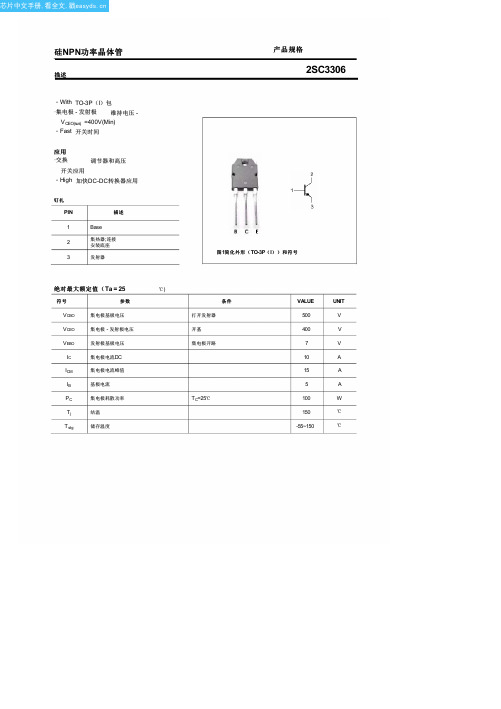
2SC3306
图 1简化外形( TO-3P( I))和符号
绝对最大额定值(Ta = 25
℃)
符号
参数
VCBO
集电极基极电压
VCEO
集电极 - 发射极电压
VEBO
发射极基极电压
IC
集电极电流DC
ICM
集电极电流峰值
IB
基极电流
PC
集电极耗散功率
Tj
结温
T stg
储存温度
条件 打开发射器 开基 集电极开路
VCC=200V; I C=5.0A IB1=-I B2=0.5A;R L=40 Ω
MIN TYP. MAX UNIT
400
V
500
V
7
V
1.5
V
2.0
V
100
μA
1.0
mA
10
1.0
μs
2.5
μs
1.0
μs
2
芯片中文手册,看全文,戳
硅NPN功率晶体管
包装外形
产品规格
2SC3306
TC=25℃
VALUE
UNIT
500
V
400
V
7
V
10
A
15
A
5
A
100
W
150
全文,戳
硅NPN功率晶体管
特性 除非另有说明 TJ = 25℃
符号
参数
V(BR)CEO 集电极 - 发射极击穿电压 V(BR)CBO 集电极基击穿电压 V(BR)EBO 发射基地击穿电压
图 2外形尺寸( unindicated公差: ±0.10 MM) 3
INA115中文资料

1010 || 6 1010 || 6
T
Ω || pF
T
Ω || pF
Input Common-Mode Range
±11
±13.5
T
T
V
Safe Input Voltage
±40
T
V
Common-Mode Rejection
VCM = ±10V, ∆RS = 1kΩ
G=1
80
96
75
90
dB
G = 10
1000
T
pF
Short Circuit Current
+20/–15
T
mA
FREQUENCY RESPONSE
Bandwidth, –3dB
G=1
G = 10
G = 100
G = 1000
Slew Rate Settling Time, 0.01%
VO = ±10V, G = 10
0.3
G=1
G = 10
q SWITCHED-GAIN AMPLIFIER q BRIDGE AMPLIFIER q THERMOCOUPLE AMPLIFIER q RTD SENSOR AMPLIFIER q MEDICAL INSTRUMENTATION q DATA ACQUISITION
DESCRIPTION
The INA115 is a low cost, general purpose instrumentation amplifier offering excellent accuracy. Its versatile three-op amp design and small size make it ideal for a wide range of applications. Similar to the model INA114, the INA115 provides additional connections to the input op amps, A1 and A2, which improve gain accuracy in high gains and are useful in forming switched-gain amplifiers.
AZ742中文资料
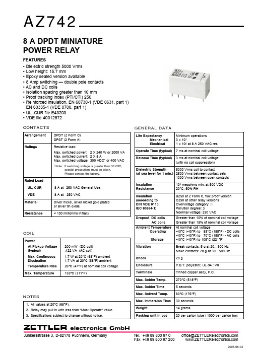
GENERAL DATALife ExpectancyMinimum operations Mechanical 3 x 10⁷Electrical 1 x 10⁵at 8 A 250 VAC res.Operate Time (typical)7 ms at nominal coil voltage Release Time (typical)3 ms at nominal coil voltage (with no coil suppression)Dielectric Strength 5000 Vrms coil to contact(at sea level for 1 min.)2500 Vrms between contact sets1000 Vrms between open contacts Insulation 105megohms min. at 500 VDC,Resistance 20°C, 50% RHInsulation B250 at 2 Form C, flux proof version (according to C250 at other relay versions DIN VDE 0110, Overvoltage category: III IEC 60664-1)Pollution degree: 3Nominal voltage: 250 VACDropout DC coilsGreater than 10% of nominal coil voltage AC coilsGreater than 15% of nominal coil voltage Ambient TemperatureAt nominal coil voltageOperating-40°C (-40°F) to 85°C (185°F) - DC coils -40°C (-40°F) to 70°C (158°F) - AC coils Storage-40°C (-40°F) to 105°C (221°F)Vibration Break contacts: 5 g at 20…500 Hz Make contacts: 20 g at 30…500 Hz Shock 20 gEnclosure P.B.T. polyester, UL-94 : V0TerminalsTinned copper alloy, P.C.Max. Solder Temp.270°C (518°F)Max. Solder Time5 seconds Max. Solvent Temp.80°C (176°F)Max. Immersion Time 30 seconds Weight14 gramsPacking unit in pcs20 per carton tube / 1000 per carton boxZET TLER8 A DPDT MINIATURE POWER RELAYFEATURES •Dielectric strength 5000 Vrms •Low height: 15.7 mm•Epoxy sealed version available•8 Amp switching — double pole contacts •AC and DC coils•Isolation spacing greater than 10 mm •Proof tracking index (PTI/CTI) 250•Reinforced insulation, EN 60730-1 (VDE 0631, part 1)EN 60335-1 (VDE 0700, part 1)•UL, CUR file E43203 •VDE file 40012572CONTACTSArrangement DPDT (2 Form C)DPST (2 Form A)RatingsResistive load:Max. switched power: 2 X 240 W or 2000 VA Max. switched current: 2 X 8 AMax. switched voltage:300 VDC* or 400 VAC* Note: If switching voltage is greater than 30VDC,special precautions must be taken.Please contact the factory.Rated Load UL, CUR 8 A at 250VAC General Use VDE 8 A at 250 VACMaterial Silver nickel, silver nickel gold plated or silver tin oxide Resistance< 100 milliohms initiallyCOILPowerAt Pickup Voltage 200 mW (DC coil)(typical).422 VA (AC coil)Max. Continuous 1.7 W at 20°C (68°F) ambient Dissipation 1.7 VA at 20°C (68°F) ambient Temperature Rise 26°C (47°F) at nominal coil voltage Max. Temperature155°C (311°F)NOTES1.All values at 20°C (68°F).2.Relay may pull in with less than “Must Operate” value.3.Specifications subject to change without notice.ZET TLER* “2A” or “2C” denote silver nickel contacts.Add suffix “G” at “2A” or “2C” for gold plated silver nickel contacts. Add suffix “E” at “2A” or “2C” for silver tin oxide contacts.Add suffix “E” at the end of order number for sealed version.COIL SPECIFICATIONS - AC COILORDER NUMBER*Nominal CoilMust OperateMax. ContinuousNominal CurrentCoil Resistance 2 Form A 2 Form C VACVACVACmA ± 10%Ohm ± 10%129.018.063.0100AZ742–2A–12A AZ742–2C–12A 2418.036.031.3400AZ742–2A–24A AZ742–2C–24A 4836.072.015.61,550AZ742–2A–48A AZ742–2C–48A 6045.090.012.52,600AZ742–2A–60A AZ742–2C–60A 11082.5165.0 6.88,900AZ742–2A–110A AZ742–2C–110A 11586.3172.5 6.59,600AZ742–2A–115A AZ742–2C–115A 12090.0180.0 6.310,200AZ742–2A–120A AZ742–2C–120A 220165.0330.0 3.435,500AZ742–2A–220A AZ742–2C–220A 230172.5345.0 3.338,500AZ742–2A–230AAZ742–2C–230A 240180.0360.03.142,500AZ742–2A–240AAZ742–2C–240ARELAY ORDERING DATACOIL SPECIFICATIONS - DC COILORDER NUMBER*Nominal CoilMust OperateMax. ContinuousCoil Resistance 2 Form A 2 Form C VDCVDCVDCOhm ± 10%3 2.17.622AZ742–2A–3D AZ742–2C–3D 5 3.512.760 AZ742–2A–5DAZ742–2C–5D 6 4.215.390AZ742–2A–6D AZ742–2C–6D 9 6.322.9200AZ742–2A–9D AZ742–2C–9D 128.430.6360 AZ742–2A–12D AZ742–2C–12D1812.645.9710AZ742–2A–18D AZ742–2C–18D 2416.861.21,440 AZ742–2A–24DAZ742–2C–24D 3625.292.03,140AZ742–2A–36D AZ742–2C–36D 4833.6122.05,700AZ742–2A–48D AZ742–2C–48D 6042.0153.07,500AZ742–2A–60D AZ742–2C–60D 11077.0280.025,200AZ742–2A–110DAZ742–2C–110DACCESSORIESMECHANICAL DATAZETTLERh = 15 ... 16.5 mm h = 15 ... 16.5 mmFor P.C.B. mount: Socket EC 50Retaining Clip MP 16 / MH 16For DIN rail mount: Socket ES 50Retaining Clip MS 16ZET TLER。
SMT贴片元件标识

J R N N DO N N DO DO DO DO DO DO DO DO DO DO DO Base CX I I X A C O X DP N N N A C C O DP N N N N K A D C O N N N
SOT23R SC70 SC59 SOT363 SC70 SC59 SOT363 SOT363 SOT363 SOT363 SOT363 SOT363 SOT363 SOT363 SOT363 SOT363 SOT363 Package SOD523 SOD323 SOT143 SOT346 SOT346 SOT89 SOT143 SOT363 SOT416 SOT23 SOT23 SOT346 SOT23 SOT346 SOT89 SOT363 SC70 SC59 SOT23 SOT23 SOT23 SOT346 SOT23 SOT346 SOT89 SC70 SC59 SOT23
BC846BPN BAS125 BAS125W MA4CS103A MUN5313DW1 MMBD1503A PZM13NB2A ZC2813E PZM13NB BZV49-C13 BAS125-04 BAS125-04W BAT114-099R DTA114EUA DTA114EKA MUN5314DW1 DTA114ECA MMBD1504A BAS125-05 BAS125-05W DTA124EUA DTA124EKA DTA124ECA MUN5315DW1 MMBT3960 MMBD1505A PZM15NB2A PZM15NB BZV49-C15 PDTC114ET PDTC114EU BAS125-06 BAS125-06W MUN5316DW1 DTA144EUA DTA144EKA PZM16NB BZV49-C16 BAS125-07 BAS125-07W PDTC124ET PDTC124EU BFP181T PDTC143ZK PDTC143ZT PDTC143ZT PZM18NB BZV49-C18 PDTA143ZK
74271112S;中文规格书,Datasheet资料
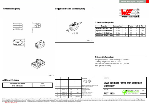
7.1 7.0 6.02012-06-272012-04-302008-01-03SStSStSMuSStSMu-Würth Elektronik eiSos GmbH & Co. KGEMC & Inductive SolutionsMax-Eyth-Str. 174638 WaldenburgGermanyTel. +49 (0) 79 42 945 - 0A Dimensions: [mm] Additional FeaturesSafety key to lock/ unkock STAR-CLIP Fixation74271 7427711D2 General Properties:Ferrite core Ferrite core Ferrite core Plastic housing Plastic housing Test cable Test cablePropertiesMaterial Initial permeability Curie temperatureColourFlammability ClassificationApplicable cable Applicable cable lengthµi T CValue 4 W 620620150Black UL94-V0AWG2690Unit°Cmm Tol.typ.typ.F Typical Impedance Characteristics:I Cautions and Warnings:The following conditions apply to all goods within the product series of WE-STAR TECof Würth Elektronik eiSos GmbH & Co. KG:General:All recommendations according to the general technical specifications of the data sheet have to be complied with.The disposal and operation of the product within ambient conditions which probably alloy or harm the component surface has to be avoided.The packaging of the product is to encase the needed humidity of the plastic housing. To ensure the humidity level, the products have to be stored in this delivered packaging. If not, the products are losing their humidity. In this case you can re-condition the components according to the internal standard WE1883 to ensure the necessary humidity in the plastic.To ensure the operating mode of the product, the ambient temperature at processing (when the part will be mounted on the cable) has to be in the range of 15 to 25 °C.Before mounting, the part should be stored for one hour in this condition.The responsibility for the applicability of customer specific products and the use in a particular customer design is always within the authority of the customer. All technical specifications for standard products do also apply for customer specific products.Direct mechanical impact to the product and the forcible closing of this shall be prevented as the ferrite material of the ferrite body or the pla-stic housing could flake or in the worst case it could break.Product specific:Follow all instructions mentioned in the datasheet, especially:•The cable diameter must be pointed out, otherwise no warranty will be sustained.•Violation of the technical product specifications such as exceeding the nominal rated current will result in the loss of warranty.1. General Customer ResponsibilitySome goods within the product range of Würth Elektronik eiSos GmbH & Co. KG contain statements regarding general suitability for certain application areas. These statements about suitability are based on our knowledge and experience of typical requirements concerning the are-as, serve as general guidance and cannot be estimated as binding statements about the suitability for a customer application. The responsibi-lity for the applicability and use in a particular customer design is always solely within the authority of the customer. Due to this fact it is up to the customer to evaluate, where appropriate to investigate and decide whether the device with the specific product characteristics described in the product specification is valid and suitable for the respective customer application or not.2. Customer Responsibility related to Specific, in particular Safety-Relevant ApplicationsIt has to be clearly pointed out that the possibility of a malfunction of electronic components or failure before the end of the usual lifetime can-not be completely eliminated in the current state of the art, even if the products are operated within the range of the specifications.In certain customer applications requiring a very high level of safety and especially in customer applications in which the malfunction or failure of an electronic component could endanger human life or health it must be ensured by most advanced technological aid of suitable design of the customer application that no injury or damage is caused to third parties in the event of malfunction or failure of an electronic component.3. Best Care and AttentionAny product-specific notes, warnings and cautions must be strictly observed.4. Customer Support for Product SpecificationsSome products within the product range may contain substances which are subject to restrictions in certain jurisdictions in order to serve spe-cific technical requirements. Necessary information is available on request. In this case the field sales engineer or the internal sales person in charge should be contacted who will be happy to support in this matter.5. Product R&DDue to constant product improvement product specifications may change from time to time. As a standard reporting procedure of the Product Change Notification (PCN) according to the JEDEC-Standard inform about minor and major changes. In case of further queries regarding the PCN, the field sales engineer or the internal sales person in charge should be contacted. The basic responsibility of the customer as per Secti-on 1 and 2 remains unaffected.6. Product Life CycleDue to technical progress and economical evaluation we also reserve the right to discontinue production and delivery of products. As a stan-dard reporting procedure of the Product Termination Notification (PTN) according to the JEDEC-Standard we will inform at an early stage about inevitable product discontinuance. According to this we cannot guarantee that all products within our product range will always be available. Therefore it needs to be verified with the field sales engineer or the internal sales person in charge about the current product availability ex-pectancy before or when the product for application design-in disposal is considered.The approach named above does not apply in the case of individual agreements deviating from the foregoing for customer-specific products.7. Property RightsAll the rights for contractual products produced by Würth Elektronik eiSos GmbH & Co. KG on the basis of ideas, development contracts as well as models or templates that are subject to copyright, patent or commercial protection supplied to the customer will remain with Würth Elektronik eiSos GmbH & Co. KG.8. General Terms and ConditionsUnless otherwise agreed in individual contracts, all orders are subject to the current version of the “General Terms and Conditions of Würth Elektronik eiSos Group”, last version available at .J Important Notes:The following conditions apply to all goods within the product range of Würth Elektronik eiSos GmbH & Co. KG:分销商库存信息: WURTH-ELECTRONICS 74271112S。
XTR115UA中文资料

®
XTR116
XTR115
XTR115 XTR116
For most current data sheet and other product information, visit
4-20mA CURRENT LOOP TRANSMITTERS
XTR115U XTR116U
PARAMETER
CONDITIONS
MIN
TYP
MAX
OUTPUT
Output Current Equation
IO
Output Current, Linear Range
Over-Scale Limit
ILIM
Under-Scale Limit
IMIN
SPAN
Span (Current Gain)
©2000 Burr-Brown Corporation
PDS-11582A
®
XTR115,PriXnteTd Rin U1.S1.A6. January, 2000
元器件交易网
SPECIFICATIONS
At TA = +25°C, V+ = 24V, RIN = 20kΩ, and TIP29C external transistor, unless otherwise noted.
V+ = 7.5V to 36V
0.25
IO = IIN • 100
32 0.2
25 0.25
100 ±0.05
±3 ±0.003
±0.2 ±20 ±0.01
±100 ±0.7 ±0.1 –35
150 0.6
±250 ±3 ±2
380 3.2
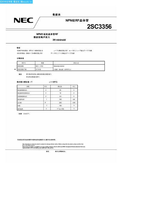
2SC3356R25中文资料(NEC)中文数据手册「EasyDatasheet - 矽搜」
–150˚ –120˚
–30˚ –150˚
–60˚ –90˚
–120˚
–30˚
–60˚ –90˚
Data Sheet PU10209EJ02V0DS
5
10
插入最功大率可增5用益功|率SV增益=M1A0GV(分贝)
I 能力= 20 mA
0 0.05 0.1 0.2
0.5
1
2
频率f(GHz)
5 插入功率增益| S
0
0.5 1
5
集电极电流I
10 (mA)
50 70
备注
该图表显示标称特性.
Data Sheet PU10209EJ02V0DS
3
芯片中文手册,看全文,戳
2%
2. 收藏家基地电容,当发射器接地
hFE 分类
秩 打标
h值
R23/Q R23
50至100
R24/R R24
80至160
R25/S R25
125至250
注意 旧规格/新规格
MIN.
TYP. MAX.
单元
–
–
1.0
µA
–
–
1.0
µA
50
120
250
–
–
7
–
GHz
–
11.5
–
dB
–
1.1
2.0
dB0.55订源自信息零件号2SC3356 2SC3356-T1B
数量
50只(不卷) 3千件/卷
供给方式
•8mm宽压花录音 •引脚3(集电极)面带穿孔方
备注
要订购评价样品,请联系您最近销售部门. 单位样品数量为50个.
绝对最大额定值(T
- 1、下载文档前请自行甄别文档内容的完整性,平台不提供额外的编辑、内容补充、找答案等附加服务。
- 2、"仅部分预览"的文档,不可在线预览部分如存在完整性等问题,可反馈申请退款(可完整预览的文档不适用该条件!)。
- 3、如文档侵犯您的权益,请联系客服反馈,我们会尽快为您处理(人工客服工作时间:9:00-18:30)。
GENERAL DATALife ExpectancyMinimum operations Mechanical 3 x 10⁷Electrical 1 x 10⁵at 8 A 250 VAC res.Operate Time (typical)7 ms at nominal coil voltage Release Time (typical)3 ms at nominal coil voltage (with no coil suppression)Dielectric Strength 5000 Vrms coil to contact(at sea level for 1 min.)2500 Vrms between contact sets1000 Vrms between open contacts Insulation 105megohms min. at 500 VDC,Resistance 20°C, 50% RHInsulation B250 at 2 Form C (according to C250 at 2 Form ADIN VDE 0110, Overvoltage category: III IEC 60664-1)Pollution degree: 3Nominal voltage: 250 VACDropout DC coilsGreater than 10% of nominal coil voltage AC coilsGreater than 15% of nominal coil voltage Ambient TemperatureAt nominal coil voltageOperating-40°C (-40°F) to 85°C (185°F) - DC coils -40°C (-40°F) to 70°C (158°F) - AC coils Storage-40°C (-40°F) to 105°C (221°F)Vibration Break contacts: 5 g at 20…500 Hz Make contacts: 20 g at 30…500 Hz Shock 20 gEnclosure P.B.T. polyester, UL-94 : V0TerminalsTinned copper alloy, P.C.Max. Solder Temp.270°C (518°F)Max. Solder Time see soldering profile Weight14 gramsPacking unit in pcs20 per carton tube / 1000 per carton boxZET TLER8 A DPDT MINIATURE POWER RELAY SMTFEATURES •Dielectric strength 5000 Vrms •Low height: 15.7 mm•8 Amp switching — double pole contacts •AC and DC coils •Flux proof version•Isolation spacing greater than 10 mm •Proof tracking index (PTI/CTI) 250•Reinforced insulation, EN 60730-1 (VDE 0631, part 1)EN 60335-1 (VDE 0700, part 1)•UL, CUR file E43203 •VDE file 40012572CONTACTSArrangement DPDT (2 Form C)DPST (2 Form A)RatingsResistive load:Max. switched power: 2 X 240 W or 2000 VA Max. switched current: 2 X 8 AMax. switched voltage:300 VDC* or 400 VAC* Note: If switching voltage is greater than 30VDC,special precautions must be taken.Please contact the factory.Rated Load UL, CUR 8 A at 250VAC General Use VDE 8 A at 250 VACMaterial Silver nickel, silver nickel gold plated or silver tin oxide Resistance< 100 milliohms initiallyCOILPowerAt Pickup Voltage 200 mW (DC coil)(typical).422 VA (AC coil)Max. Continuous 1.7 W at 20°C (68°F) ambient Dissipation 1.7 VA at 20°C (68°F) ambient Temperature Rise 26°C (47°F) at nominal coil voltage Max. Temperature155°C (311°F)NOTES1.All values at 20°C (68°F).2.Relay may pull in with less than “Must Operate” value.3.Specifications subject to change without notice.ZET TLER* “2A” or “2C” denote silver nickel contacts.Add suffix “G” at “2A” or “2C” for gold plated silver nickel contacts. Add suffix “E” at “2A” or “2C” for silver tin oxide contacts.COIL SPECIFICATIONS - AC COILORDER NUMBER*Nominal CoilMust OperateMax. ContinuousNominal CurrentCoil Resistance 2 Form A 2 Form C VACVACVACmA ± 10%Ohm ± 10%129.618.063.0100AZ742S–2A–12A AZ742S–2C–12A 2419.236.031.3400AZ742S–2A–24A AZ742S–2C–24A 4838.472.015.61,550AZ742S–2A–48A AZ742S–2C–48A 6048.090.012.52,600AZ742S–2A–60A AZ742S–2C–60A 11088.0165.0 6.88,900AZ742S–2A–110A AZ742S–2C–110A 11592.0172.5 6.59,600AZ742S–2A–115A AZ742S–2C–115A 12096.0180.0 6.310,200AZ742S–2A–120A AZ742S–2C–120A 220176.0330.0 3.435,500AZ742S–2A–220A AZ742S–2C–220A 230184.0345.0 3.338,500AZ742S–2A–230AAZ742S–2C–230A 240192.0360.03.142,500AZ742S–2A–240AAZ742S–2C–240ARELAY ORDERING DATACOIL SPECIFICATIONS - DC COILORDER NUMBER*Nominal CoilMust OperateMax. ContinuousCoil Resistance 2 Form A 2 Form C VDCVDCVDCOhm ± 10%3 2.257.622AZ742S–2A–3D AZ742S–2C–3D 5 3.7512.760 AZ742S–2A–5DAZ742S–2C–5D 6 4.515.390AZ742S–2A–6D AZ742S–2C–6D 9 6.7522.9200AZ742S–2A–9D AZ742S–2C–9D 129.030.6360 AZ742S–2A–12D AZ742S–2C–12D 1813.545.9710AZ742S–2A–18DAZ742S–2C–18D 2418.061.21,440 AZ742S–2A–24DAZ742S–2C–24D 3627.092.03,140AZ742S–2A–36D AZ742S–2C–36D 4836.0122.05,700AZ742S–2A–48D AZ742S–2C–48D 6045.0153.07,500AZ742S–2A–60D AZ742S–2C–60D 11082.5280.025,200AZ742S–2A–110DAZ742S–2C–110DZET TLER45784578NOTESThe soldering profile to the left is an example and is just to show one of various profiles AZ742S has been tested with.In order to make sure AZ742S fits to a specific profile, we strongly recommend to test under the real environment.ZET TLER。