Pegasor AQ Urban 设备连接
华硕2.1渣冰音箱Home Theater系统快速引导指南说明书

The LED indicator on the front of the main unit will show which mode is currently in use.
While playing, press the NEWS / MOVIE / MUSIC buttons on the remote control to select the preset equalizers:
10 BASS + , BASS - Increase/decrease the bass level.
11 SOURCE
Select the play mode.
First-time use:
Put the 2 x AAA batteries (included) into the remote control before use.
Bluetooth
DEVICES
1
2
Hisense HS214 Connected
3
Now Discoverable
6 Wall Mounting
540MM
1
(ON/OFF) Switch the unit between ON and
STANDBY mode.
1
2
(MUTE)
Mute or resume volume.
3
3 EQ buttons 4 VOL+/VOL-
5
,
Select MOVIE/MUSIC/NEWS sound e ect. 4
Increase/decrease the volume level.
蓝联智能连接设置指南:美好的联动设备智能Wi-Fi热水器规划程序可编程智能Wi-Fi温度器PRS73

Wi-Fi Setup GuideUniversal Programmable Smart Wi-Fi ThermostatLeave this setup guidewith thermostat.PRS7325WF-105-013Wire and Install Thermostat• Properly wire and configure thermostat.Refer to the installer guide.• Refer to the user manual for programmingand maintenance.Before beginning setup you will need to:• Know your Wi-Fi network name and password• Have a valid e-mail address• Get the FREE appApple ® Devices:Download the BlueLink Smart Connect ® applicationfrom the Apple ® App StoreAndroid TM Devices:Download the BlueLink Smart Connect ® applicationfrom the Google Play StoreDesktop Computer:Go to and create an account.NOTE: For Registration, your desktop PC must have awireless connection.3.1 Open the BlueLink Smart Connect App.Select REGISTER and enter a valid e-mail address.3.2 Scan or enter the thermostat serial number.You can locate this number on the back of thethermostat or on the enclosed thermostatregistration card.NOTE: If you removed the thermostat to locate theserial number, make sure to reconnect it beforeselecting ENTER .3.3 Complete the remaining registration screens.Once you reach the Create Account screen,select REGISTER .Login and Register 4.1 Enter your network name (SSID) and password,select ENTER .NOTE: The network name and password arecase sensitive fields.The application will now instruct you to put thethermostat into Wi-Fi connect mode.4Enter Network Information12Set-Up for ConnectionNOTE: Wi-Fi works without common (C)wire on most systems; requires common onheat pump, heat only or cool only systemsHelpful videos can be found at /wifi.powered byModel PRS7325WFEnable Wi-Fi on Thermostat5.1 On the thermostat, press and hold theHOLD and RETURN buttons for3 seconds.5.25+6.1 The application will prompt you to goto your smartphone, tablet or computerWi-Fi settings and select the bluelink_wifi network. See samples shown.NOTE:Do not exit the application. Minimize it so that you can return to the same screen afterselecting the bluelink_wifi network. This isusually done by pressing the home button on your smart phone or tablet.Connect to Thermostat 6Android TM Sample Apple ® SampleComplete Setup7.1 After selecting the bluelink_wifi network, use the home key to return to the application and select OK.7.2 The word WAIT will appear in thethermostat display.7.3 Once a connection is made, Connection Successful will appear in the application screen. At thermostat, your network name followed by the MAC address will appear.7.4At thermostat, press RETURN to exit Wi-Fi setup mode.NOTE: After setup is complete, make sure toreturn your phone or tablet to the original wireless network.7844-BLU-LINK (844-258-5465) (U.S.)©2018 PROPARTS • All Rights Reserved • Made in China.PRS7325WF-105-01Record Network Information for Future ReferenceNetwork Name (SSID)Network PasswordThermostat Serial Number #You may need this information later or if calling for support.Visit for helpful videos.Apple and the Apple logo are trademarks of Apple Inc., registered in the U.S. and other countries. App Store is a service mark of Apple Inc. All other trademarks are the property of their respective owners.Changing Your Wi-Fi SettingsFirst Clear Your Thermostat Wi-Fi Settings1. Press and hold the RETURN button for 4 seconds.2. The display will change showing the first User Option.3. Press RETURN until you see the word WIFI in the display .4. Press the button until WIFI CL appears.5. Press RETURN to exit and clear all Wi-Fi settings.Then Update Your App Settings1. Open the app and select Update Account .2. Enter your account password.3. Select Wi-Fi Settings .4. Select the thermostat you wish to change.5.Choose WI-FI Network or WI-FI Password and select Enter.6. Update the information and select Enter .NOTE: To complete setup, follow the instructions inthe app and refer to sections 5 - 7.NOTE: (SSID)If you are not connected to 24 VAC, the thermostatwill display POWR NO (No Power).。
爱达斯Aegis防护设备安装指南说明书
Installation Instructions for Eaton’s Aegis Surge Protective Device AGPHxxxxx and AGPVxxxxxContentsD e scription Pag eIntroduction . . . . . . . . . . . . . . . . . . . . . . . . . . . . . .2Safety Precautions . . . . . . . . . . . . . . . . . . . . . . . . .2Operation . . . . . . . . . . . . . . . . . . . . . . . . . . . . . . . .2Preparation . . . . . . . . . . . . . . . . . . . . . . . . . . . . . .2Installation Procedures . . . . . . . . . . . . . . . . . . . . .3Enclosure Mounting (New Applications -Aegis PH and Aegis PV) . . . . . . . . . . . . . . . . . .3Enclosure Mounting (Existing Aegis HWapplications) . . . . . . . . . . . . . . . . . . . . . . . . . . .3Wiring Instructions Aegis PH . . . . . . . . . . . . . . . . .3Enclosure Mounting (Existing Aegis VLapplications) . . . . . . . . . . . . . . . . . . . . . . . . . . .5Wiring Instructions Aegis PV . . . . . . . . . . . . . . . . .5Specifications . . . . . . . . . . . . . . . . . . . . . . . . . . . .7Diagnostics . . . . . . . . . . . . . . . . . . . . . . . . . . . . . .7Maintenance . . . . . . . . . . . . . . . . . . . . . . . . . . . . .7Terms and Conditions . . . . . . . . . . . . . . . . . . . . . .7Warranty . . . . . . . . . . . . . . . . . . . . . . . . . . . . . . . .8Aegis PHAegis PV2Instruction Manual IM01005021EEffective April 2014Installation Instructions for Eaton’s Aegis Surge Protective Device AGPHxxxxx and AGPVxxxxxEATON IntroductionEaton’s Aegis PH and PV products are premium Surge Protective Devices (SPDs) with filtering . They are applied to protect sensitive electronic equipment (critical loads) from transients and electrical line noise . Correct installation is critical for the proper operation of the Aegis PH and PV units . Please read the installation and operat-ing instructions prior to installing the Aegis PH or PV .Safety PrecautionsWARNINGIMPROPER INSTALLATION COULD CAUSE DEATH, INJURY AND EQUIPMENT DAMAGE. FOLLOW ALL WARNINGS AND CAUTIONS. COMPLETELY READ AND UNDERSTAND THE INFORMATION IN THIS MANUAL BEFORE ATTEMPTING TO INSTALL OR OPERATE THIS EQUIPMENT.WARNINGIMPROPER WIRING COULD CAUSE DEATH, INJURY AND/OR EQUIPMENT DAMAGE. ONLY LICENSED/QUALIFIED ELECTRICIANS WHO ARE TRAINED IN THE INSTALLATION AND SERVICE OF ELECTRICAL SERVICES ARE TO INSTALL AND SERVICE THIS EQUIPMENT.WARNINGHAZARDOUS VOLTAGES ARE PRESENT INSIDE THE SPD DURING NORMAL OPERATION. FOLLOW ALL SAFE PRACTICES TO AVOID ELECTRICAL SHOCK.OperationProperly installed, Aegis PH and PV products will protect electronic equipment from surges and electrical line noise . They are installed in series with the load to be protected . Under normal conditions, the Aegis PH and PV will only draw a small capacitive current from the line . When electrical surges or line noise exists, the Aegis PH and PV will remove that portion of the disturbance .PreparationBefore installation, verify that the amperage and voltage ratings of the Aegis PH or PV match the application . The maximum amper-age rating of the Aegis PH and PV are identified on the nameplate located on the side of the enclosure . The maximum amperage of the critical load must be equal to or less than the Aegis PH or PV being installed . If the amperage rating is exceeded, the unit can overheat and fail .To verify the voltage rating, check the nameplate on the side of the Aegis enclosure . The maximum voltage will be the same from Line to Neutral (L -N), Line to Ground (L -G), and Neutral to Ground (N-G) . This makes the Aegis PH and PV suitable for bonded systems that are L, N, G as shown in Figures 1 and 3 or for Unbonded systems that utilize L, L, G as shown in Figures 2 and 4 . The amperage and voltage rating is also indicated in the catalog number . The catalog number can also be found on the nameplate .Review the application to ensure physical space exists for the Aegis product installation . Review and check the grounding system . All grounding and bonding systems must meet NEC, CEC and/or appli-cable local codes . A poor ground or grounding and bonding viola-tions will seriously affect the ability of the Aegis PH and PV to func-tion as specified .The Aegis PH and PV input ground and output ground are internally wired together . Loads that require a separate ground must use the output ground from the Aegis PH and PV . Loads that are grounded to the chassis of the equipment do not require the output ground from the Aegis PH and PV to prevent ground loops . The Aegis PH and PV input ground should be connected to the local ground point in all installations .Overcurrent protection is required to protect the distribution system from an unlikely failure of the Aegis PH and PV or downstream load . Overcurrent protection must be sized according to the downstream load with an additional 1, 1 .5, or 2 .5 ampere margin for the Aegis PH and PV capacitive current draw as shown in Table 1 . The circuit breaker sizes shown in Table 2 are based on safety testing of the Aegis units and represent the maximum allowable sizes .T able 1. Capacitive CurrentVoltage Frequency Capacitive Current120V 50 to 60 Hz 1 amp 120V 400 Hz 2.5 amp 220V50 to 60 Hz1.5 ampThis ampere margin is especially important for loads under five (5) amperes . The ampere current draw of the Aegis is capacitive and may increase if there is significant noise on the power line . This will not detract from the output current rating of the Aegis PH and PV as the current rating of the Aegis PH and PV is based on the output current only .An external circuit breaker in series with the load is required for a permanently connected two-port SPD and shall be suitably rated for branch-circuit protection in accordance with the National Electrical Code, ANSI/NFPA-70 and Canadian Electrical Code (CEC) . See Table 2 . Circuit Breaker Requirements .T able 2. Circuit Breaker RequirementsAegis Model Circuit Breaker Ratings Aegis PV 7A, 240V/415V, 10kA Min. AIC Rating Aegis PH25A, 240V/415V, 10kA Min. AIC Rating3Instruction Manual IM01005021EEffective April 2014Installation Instructions for Eaton’s Aegis Surge Protective Device AGPHxxxxx and AGPVxxxxxEATON InstallationWARNINGINSTALLING AN SPD THAT IS IMPROPERLY RATED FOR THE ELECTRICAL SYSTEM VOLTAGE COULD CREATE A POTENTIALLY HAZARDOUS CONDITION, RESULTING IN INJURY OR EQUIPMENT DAMAGE.CAUTIONEATON SPD PRODUCTS MUST BE INSTALLED OR REPLACED BY A QUALIFIED ELECTRICIAN TO AVOID INJURY OR EQUIPMENT DAMAGE.WARNINGTURN OFF THE POWER SUPPLY BEFORE WORKING IN ANY ELECTRICAL CABINET OR ON ANY CIRCUIT BREAKER PANEL. FAILURE TO DO SO COULD RESULT IN INJURY OR DEATH FROM ELECTRICAL SHOCK.NOTICEA POOR GROUND, OR GROUNDING/BONDING VIOLATIONS, COULD PREVENT THE SPD FROM PERFORMING AS SPECIFIED.For optimal protection, place the Aegis PH and PV as close as possi-ble to the load being protected . Eaton recommends that the wiring from the Aegis PH and PV output terminals to the input terminals of the electronic equipment be kept as short and straight as possible . This will prevent the wiring from acting as an antenna that picks up high frequency noise from the environment . Wiring length to the input terminals of the Aegis PH and PV is not critical .•To prevent the risk of electrical shock, TURN OFF and Lock Out all power sources to the electrical circuit where the Aegis PH and PV is to be installed .•Verify that the power has been disconnected with a portable volt-meter or other measuring device .Enclosure Mounting (New applications)Every Aegis PH and PV includes a DIN Rail and two mountingscrews (#8 Sheet metal screw) to mount the device . Drill appropri-ate hole sizes, based on material and thickness, at desired spacing using the DIN Rail slots as a template . After the DIN Rail has been secured, engage the Aegis PH or PV base (Output side, enclosure bottom) of the DIN Clip onto the DIN Rail and compress DIN clip spring by pushing the enclosure towards the Input terminal side of the enclosure bottom until the opposite side of the DIN Clip hook engages the DIN Rail . Then slowly release the spring pressure of the DIN clip securing the Aegis enclosure to the DIN Rail . Proceed to the appropriate Wiring Instructions .Enclosure Mounting (Existing Aegis HW applications)Aegis HW devices were mounted either with the use of a DIN Rail or by the enclosure’s base feet with two screws . If the device was mounted using the enclosure’s base feet, uninstall the Aegis HW and dispose of the old hardware . If the Aegis HW was mounted using the DIN Rail feature, place a screwdriver in the slot on the DIN Clip (Output side at bottom of enclosure), pulling the DIN Clip out to release the enclosure from the DIN Rail . If the previous device was DIN Rail mounted you can reuse the existing DIN Rail to mount the new Aegis PH device . Engage the Aegis PH base (Output side, enclosure bottom) of the DIN Clip to the DIN Rail and compress DIN clip spring by pushing the enclosure towards the Input terminal side of the enclosure until the opposite side of the DIN Clip hook engages . Then slowly release the spring pressure securing the Aegis PH enclosure to the DIN Rail .Wiring Instructions Aegis PH - Install an overcurrent protection device on the input side of the Aegis PH . Wire from the overcur-rent protection device to the input terminal(s) of the Aegis PH . The terminals are marked L, N, and G . Wire gauge should be selected to match the amperage of the overcurrent protection device . Ensure that the proper color wire is used (green or green/yellow – ground, white or light blue – neutral, black and/or red – phase) . Tighten all input and output terminal connections to 9 lb-in . Wire from the Aegis PH output terminals to the input terminals of the protected load . Tighten all input and output terminal connections to 9 lb-in . Install terminal block covers by pressing into place on both the input and output terminals . If the Form C contact is used for remote monitoring there will be one – N .O . and one – N .C . contact . The terminal connections are labeled on the top of the enclosure . To activate, connect the Form C output terminals to an alarm, light or building monitoring system . Tighten all Form C terminal connections to 4 lb-in . The relay is rated for a maximum of 250V and 8 amperes . Recheck all connections . Restore power to the electrical circuit . Check that the status indicator (green LED) is illuminated . If using the Form C relay contact, check to see that it is operating as desired .Figure 1. Aegis PH Dimensions.4Instruction Manual IM01005021EEffective April 2014Installation Instructions for Eaton’s Aegis Surge Protective Device AGPHxxxxx and AGPVxxxxxEATON Figure 2. Aegis PH Premium Hybrid Filter Bonded System Block Diagram.Figure 3. Aegis PH Premium Hybrid Filter Unbonded System Block Diagram.5Instruction Manual IM01005021EEffective April 2014Installation Instructions for Eaton’s Aegis Surge Protective Device AGPHxxxxx and AGPVxxxxxEATON Enclosure Mounting (Existing Aegis VL applications)CAUTIONTHE INPUT AND OUTPUT TERMINAL LOCATIONS ARE NOT POSITIONED ON THE SAME SIDE OF THE ENCLOSURE TOP COVER AS THE FORMER AEGIS VL MODELS. ROUTE WIRING TO ACCOMMODATE THE NEW INPUT AND OUTPUT TERMINAL LOCATIONS.Aegis VL devices mounted to a DIN Rail using the attached DIN clip . Remove the existing device from the DIN Rail by placing a screw driver in slot on the DIN Clip (Output side at base), pulling the DIN Clip out to release the enclosure from the DIN Rail . Now install the Aegis PV device using the attached DIN clip mounted on the bottom of the enclosure . Engage the Aegis PV base (Output side, enclosure bottom) of the DIN Clip to the DIN Rail and compress DIN clip spring by pushing the enclosure towards the Input terminal side of theenclosure until the opposite side of the DIN Clip hook engages . Then slowly release the spring pressure securing the Aegis PV enclosure to the DIN Rail .Wiring Instructions Aegis PV - Install an overcurrent protection device on the input side of the Aegis PV . Wire the overcurrent pro-tection device to the input terminal(s) of the Aegis PV . The terminals are marked L, N, and G . Wire gauge should be selected to match the amperage of the overcurrent protection device . Ensure that the proper color wire is used (green or green/yellow – ground, white or light blue – neutral, black and/or red – phase) . Wire from the Aegis PV output terminals to the input terminals of the protected load . Tighten all input and output terminal connections to 9 lb-in . Install terminal block covers by pressing into place on both the input and output terminals . Recheck all connections . Restore power to the electrical circuit . Check that the status indicator (Green LED) is illu-minated .Figure 4. Aegis PV Dimensions.6Instruction Manual IM01005021EEffective April 2014Installation Instructions for Eaton’s Aegis Surge Protective Device AGPHxxxxx and AGPVxxxxxEATON Figure 5. Aegis PV Premium Filter Bonded System Block Diagram.Figure 6. Aegis PV Premium Filter Unbonded System Block Diagram.7Instruction Manual IM01005021EEffective April 2014Installation Instructions for Eaton’s Aegis Surge Protective Device AGPHxxxxx and AGPVxxxxxEATON DiagnosticsThe Aegis PH and PV are supplied with a green LED that will illumi-nate and indicate power at the output terminals . If the green LED is not illuminated, it indicates that power is not being supplied to the Aegis . The LED will not illuminate if there has been a utility power failure, or an internal failure of the Aegis suppression components . If the internal suppression components fail, a short circuit will result . The short circuit will open the overcurrent device on the power sup-ply, removing power to the Aegis . Whenever power is removed from an Aegis PH or PV , the green LED will not illuminate, and the optional monitoring relay (Form C contact), if installed, will change state .MaintenancePreventive Maintenance (Inspection and Cleaning) – Periodic system inspections, cleaning, and connection checks are recom-mended to ensure reliable system performance . There is no defined schedule for preventive maintenance, as conditions will vary from installation to installation .Corrective Maintenance (Repair or Replacement) – the Aegis PH and PV are designed to provide years of continuous service . However, even the most reliable equipment may fail . In the unlikely case that the LED monitor or remote monitoring (Form C contact) indicates a failure, check the overcurrent protection on the power supply . Replace or reset the overcurrent protection . If a problem still exists, contact Eaton’s Surge Protection application support at: 1-800-809-2772, option 4, option 2 .Terms and Conditions of SaleThe Terms and Conditions of Sale are listed in the Eaton Selling Policy, Publication No . SP03000001E .SpecificationsT able 3. SpecificationsApplication Aegis PH2 W&G Grounded Systems Aegis PV2 W&G Grounded Systems Input Voltage 120V, 220V, 240Vac single-phase 120V, 220V, 240Vac single-phase Amperage 3, 5, 10, 15, & 20 amperes 1, 3, 5 amperes Frequency 50/60 Hz 50/60 Hz Protection Modes L-N, L-G, & N-G L-N, L-G, & N-G MCOV150V & 275V 150V & 275V Noise Attenuation (Normal Mode)75dB @ 110 KHz 50dB @ 100 KHz Filter Bandwidth 10 kHz to 100 MHz 10 kHz to 100 MHz Total Peak Surge Current 30kA per mode20kA per modeOperating Temperature -40°F to +122°F (-40°C to +50°C)-40°F to +122°F (-40°C to +50°C)Response Time Less than one nanosecondLess than one nanosecondAgency Approvals UL 1449 3rd Edition, UL 1283 5th Edition, CSAUL 1449 3rd Edition, UL 1283 5th Edition , CSAWarranty 10 years standard / 5 additional years if registered on-line **10 years standard / 5 additional years if registered on-line **Form C Contacts YesNoExternal Circuit Breaker*25A, 240V/415V, 10kA Min. AIC Rating 7A, 240V/415V, 10kA Min. AIC Rating RoHS CompliantYesYes*External circuit breaker sold separately.**Register products on-line at /spd. Then click on “Warranty Registration”.Instruction Manual IM01005021E Effective April 2014Installation Instructions for Eaton’s Aegis Surge Protective Device AGPHxxxxx and AGPVxxxxxEatonElectrical Sector1000 Eaton Boulevard Cleveland, OH 44122United States877-ETN-CARE (877-386-2273) © 2014 EatonAll Rights ReservedPrinted in USAPublication No. IM01005021E / TBG001040 April 2014Eaton is a registered trademarkAll other trademarks are property of their respective owners.WarrantyEaton warrants these products for a period of 10 years from the date of delivery to the purchaser, 15 years if the product is properly registered with Eaton, to be free from defects in both workmanship and materials . Eaton assumes no risk or liability for results of the use of the products purchased from it, including but without limiting the generality of the foregoing: (1) The use in combination with any electrical or electronic components, circuits, systems, assemblies, or any other materials or substances; (2) Unsuitability of any product for use in any circuit or assembly .Register products on-line at www .eaton .com/spd . After the page opens click on the “Warranty Registration” link in the right hand column .Purchaser’s rights under the warranty shall consist solely of requir-ing Eaton to repair, or at Eaton’s sole discretion, replace, free of charge, F .O .B . factory, and defective items received at said factory within said term determined by Eaton to be defective . The giving of or failure to give any advice or recommendations by Eaton shall not constitute any warranty by or impose any liability upon Eaton . The foregoing constitutes the sole and exclusive liability of Eaton AND IS IN LIEU OF ANY AND ALL OTHER WARRANTIES EXPRESSED, IMPLIED OR STATUTORY AS TO THE MERCHANTABILITY, FITNESS FOR PURPOSE SOLD, DESCRIPTION, QUALITY, PRODUCTIVENESS OR ANY OTHER MATTER .In no event shall Eaton be liable for special or consequential dam-ages or for delay in performance of the warranty .This warranty does not apply if the product has been misused, abused, altered, tampered with, or used in applications other than specified on the nameplate . At the end of the warranty period, Eaton shall be under no further warranty obligation expressed or implied . The product covered by this warranty certificate can only be repaired or replaced by the factory . For help on troubleshooting the SPD, or for warranty information, call 1-800-809-2772, Option 4, sub-option 2 . Repair or replacement units will be returned collect . If Eaton finds the return to be a manufacturer’s defect, the product will be returned prepaid .。
PCI-R5001 系列人脸识别终端 安装使用手册说明书

安装使用手册声明非常感谢您购买我公司的产品,如果您有什么疑问或需要请随时联系我们。
◼我们已尽量保证文档内容的完整性与准确性,但也不免出现技术上不准确、与产品功能及操作不相符或印刷错误等情况,如有任何疑问或争议,请以我司最终解释为准。
◼产品和文档将实时进行更新,恕不另行通知。
◼本文档中内容仅为用户提供参考指导作用,请以实际内容为准。
历史版本目录产品介绍 (1)产品简介 (1)产品外观 (2)硬件接口 (3)网络架构 (3)安装说明 (4)壁挂安装方式 (4)安装示意图 (4)详细安装步骤 (5)闸机安装方式 (6)安装示意图 (6)详细安装步骤 (7)设备接线指引 (8)设备接线(带门禁扩展模块) (8)使用操作 (9)设备启动 (9)设置日期时间 (9)主页面 (10)刷脸模式 (11)刷卡模式 (13)刷卡加人脸模式 (13)刷卡加密码模式 (15)密码开门模式 (16)远程开门模式 (17)识别距离提示 (18)门禁常开常闭提示 (19)消防联动提示 (20)进入配置界面 (21)人员库 (22)本地人员库 (23)联网人员库 (24)识别记录 (24)本地记录 (25)联网记录 (25)记录导出 (26)本地登记 (27)人员更新 (28)算法设置 (29)开启活体 (30)1:N人脸识别阈值 (30)识别距离 (30)帽子检测 (31)注册参数 (32)核验模式 (33)设备接口 (35)韦根协议 (36)开关量信号 (37)RS232串口 (37)设备IO输入 (39)网络配置 (39)通用设置 (41)隐私显示 (42)日期时间 (42)门禁设置 (43)显示设置 (45)语音设置 (46)设备重启 (47)管理员密码 (48)重置 (49)关于设备 (50)登记人脸标准规范 (51)常见问题处理 (54)注意事项 (56)产品介绍产品简介PCI-R5001是佳都科技研发的新一代5英寸屏幕的人脸智能终端产品,采用国际一流工业设计标准,追求极致品质,具有人脸识别速度快、精度高、可防伪、扩展灵活等特点。
Aruba 320系列接入点说明书

●320 系列接入点●9/16" 和 15/16” 吊架轨道适配器如果发现任何不正确、缺失或损坏的部件,请通知您的供应商。
要退还本产品,请将此设备和其他随附的材料放入原始包装内装好,然后退还给供应商。
安装本设备必须由经过培训的 Aruba 认证移动专业人员 (ACMP) 或有类似资格的 Aruba 认证技术人员安装和维修。
安装本设备之前,请参阅 Aruba 320 Series Access Point Installation Guide (Aruba 320系列接入点安装指南),为此请扫描本节给出的二维码,或者访问 上的 Documentation (文档)选项卡,然后选择 Hardware Installation Guides (硬件安装指南)> Access Points (接入点)> 320 Series (320 系列)。
软件有关初始设置和软件配置的说明,请参阅最新版本的 AP Software Quick Start Guide (接入点软件快速开始指南),为此请扫描本节给出的二维码代码,或者访问 上的 Documentation (文档)选项卡,然后选择 Software User & Reference Guides (软件用户及参考指南) > Aruba Unified 。
Aruba 320 系列校园接入点启动指南0512031-CN-05Aruba 320系列园区访问点(AP-324,AP-325,IAP-324, 和IAP-325)支持用于高性能WLAN的IEEE 802.11标准。
这些接入点提供高性能802.11n 2.4GHz 和802.11ac 5GHz功能,同时还支持802.11a / b / g无线服务。
在5GHz模式下支持多用户多输入多输出(MU-MIMO),以实现最佳性能。
AP-324和AP-325与Aruba控制器配合使用,而IAP-324和IAP-325可以通过内置的虚拟控制器进行配置。
WNA1100 N150无线USB适配器安装指南说明书
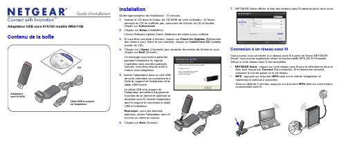
Guide d'installation Adaptateur USB sans fil N150 modèle WNA1100Contenu de la boîteCD InstallationDurée approximative de l'installation : 10 minutes.1. Insérez le CD dans le lecteur de CD-ROM de votre ordinateur. Si l'écranprincipal du CD ne s'affiche pas, parcourez les fichiers du CD et double-cliquez sur Autorun.exe.2. Cliquez sur Setup (Installation).L'écran Software Update Check (Détection de mises à jour) s'affiche.3. Si vous êtes connecté à Internet, cliquez sur Check for Updates (Rechercherdes mises à jour). Dans le cas contraire, cliquez sur Install from CD (Installerà partir du CD).4. Cliquez sur I Agree (J'accepte) pour accepter les termes de la licence, puiscliquez sur Next (Suivant).pendant l'installation du logiciel.L'opération peut prendre quelquesinsérer votre adaptateur.5.câble USB fournis.Le câble USB et le support deUSB à l'ordinateur.Remarque : pour des résultatsà moins un mètre du routeur.6. Cliquez sur Next(Suivant).7. NETGEAR Genie affiche la liste des réseaux sans fil présents dans votre zone.Connexion à un réseau sans filVous pouvez vous connecter à un réseau sans fil à partir de l'écran NETGEARGenie. Vous pouvez également utiliser la fonctionnalité WPS (Wi-Fi ProtectedSetup) si votre réseau sans fil est compatible.• NETGEAR Genie : cliquez sur votre réseau sans fil pour le sélectionner dans laliste, puis cliquez sur Connect (Se connecter). Si le réseau est sécurisé,saisissez le mot de passe ou la clé réseau.• WPS : appuyez sur le bouton WPS situé sur le côté de l'adaptateur etmaintenez-le enfoncé 2 secondes.Dans un délai de 2 minutes, appuyez sur le bouton WPS situé sur votre routeurMai 2011Ce symbole a été apposé conformément à la directive européenne 2002/96 sur la mise au rebut des équipements électriques et électroniques (directive WEEE - Waste Electrical and ElectronicEquipment). En cas de mise au rebut de ce produit dans un Etat membre de l'Union européenne, il doit être traité et recyclé conformément à cette directive.©2011 par NETGEAR, Inc. Tous droits réservés. NETGEAR et le logo NETGEAR sont des marques déposées de NETGEAR, Inc. aux Etats-Unis et/ou dans d'autres pays. Les autres marques ou noms de produits sont des marques commerciales ou des marques déposées de leurs détenteurs respectifs. Ces informations sontsusceptibles d'être modifiées sans préavis.L'adaptateur se connecte au réseau (l'opération peut prendre plusieurs minutes). Vos paramètres sont enregistrés dans un profil.Icône NETGEAR GenieLorsque vous installez votre adaptateur, l'icône NETGEAR Genie s'affiche dans la zone de notification Windows et sur le bureau. Cliquez sur cette icône pour ouvrir NETGEAR Genie et apporter des modifications ou établir une connexion vers un autre réseau sans fil. La couleur de l'icône indique le niveau de puissance de votre connexion sans fil, de zéro à cinq barres.Vert : 3 à 5 barres Jaune : 1 ou 2 barresRouge : 0 (zéro) barre, aucune connexionSi vous retirez l'adaptateur, NETGEAR Genie n'est pas disponible et l'icône ne s'affiche pas. Elle s'affiche à nouveau si vous réinsérez l'adaptateur.Assistance techniqueNous vous remercions d'avoir choisi les produits NETGEAR.Après l'installation de votre périphérique, notez le numéro de série inscrit surl'étiquette de votre produit. Il vous sera nécessaire pour enregistrer votre produit à l'adresse gear.fr/support/. Vous devez être enregistré pour utiliser le service d'assistance téléphonique. Nous vous recommandons vivement de procéder à l'enregistrement sur le site Web NETGEAR.Visitez le site gear.fr/support/ pour obtenir des mises à jour de produits et consulter le support Web.Pour en savoir plus sur l'installation, la configuration et l'utilisation de votre adaptateur USB sans fil, reportez-vous au Manuel de l'utilisateur .Pour consulter la déclaration de conformité complète, rendez-vous sur le site Web NETGEAR des déclarations de conformité pour l'UE à l'adresse : /app/answers/detail/a_id/11621/.Pour obtenir des informations sur la licence publique générale GNU (GPL),rendez-vous à l'adresse : /app/answers/detail/a_id/2649.。
艾贝斯灯联网智慧城市照明管理云平台使用说明书
《EH100灯联网产品系列》灯联网智慧城市照明管理云平台使用说明书艾贝斯能效科技成都艾贝斯科技发展有限公司目录一、概述 (5)二、用户使用 (5)1、用户登录 (5)2、设备菜单 (6)3、首页 (6)4、设备管控 (7)4.1集中控制 (7)4.2、单灯控制 (9)4.3面板控制 (10)4.4防盗监控 (11)4.5视频监控 (12)4.6设备官网 (12)4.7设备管理 (12)4.8系统设置 (15)5、能耗管理 (16)5.1能耗监控 (16)5.5电表管理 (17)5.6功率趋势: (18)6、设备维护 (18)6.1故障预警 (18)6.2故障申报: (19)6.3故障统计 (20)6.4故障分析 (20)6.7历史数据 (20)6.8任务中心 (21)6.9技术支持 (21)6.10报警通知设置 (22)6.11维护派单 (23)7、ERP管理 (23)8、智慧路灯 (25)8.1智慧路灯管理 (25)8.2环境采集 (25)9、快捷操作 (26)9.1一键开关 (26)9.2一键设置 (26)9.3一键巡检 (26)9.4一键抄表 (26)9.5设备亮灯率 (26)9.6预警信息 (26)9.7一键查询 (26)9.8单灯亮率 (26)10、系统管理 (26)10.1数据备份 (26)10.2账户管理 (26)三、版本说明 (27)四、售后与维护 (27)使用本说明书欢迎您使用艾贝斯灯联网产品。
本说明书介绍了该产品的多种功能、使用方法和注意事项。
使用设备前请先仔细阅读本说明书。
法律声明:版权所有©成都艾贝斯科技发展有限公司,保留一切权利。
未经成都艾贝斯科技发展有限公司书面同意,任何单位和个人不得擅自摘抄、复制本手册内容的部分或全部,并不得以任何形式传播。
本手册描述的产品中,可能包含成都艾贝斯科技发展有限公司及其可能存在的许可人享有版权的软件。
除非获得相关权利人的许可,否则任何人不能以任何形式对上述内容进行复制、分发、修改、摘录、反编译、反汇编、解密、反向工程、出租、转让、分许可等侵犯软件版权的行为。
FLIR DNR300系列快速连接指南说明书

4. Click OK.
NOTE: See the included manual on CD for details on configuring Daylight Savings Time and Network Time Protocol.
Ethernet Extension Cable* NOTE: It may take up to 1 minute for cameras to start up and transmit video to your NVR.
Connect caras to a Router* or Switch* on your LAN. If your NVR has more than 8 channels, this is required to connect channels 9 and higher**
2. Click Setting > General.
3. Enter the current date (MM DD YYYY) and time (HH MM SS) under System Time. Set the date and time. Click Save.
Set the date and time Click Save
Quick Connection Guide
DNR300 Series
Network Video Surveillance Recorder
PACKAGE CONTENTS:
- 1、下载文档前请自行甄别文档内容的完整性,平台不提供额外的编辑、内容补充、找答案等附加服务。
- 2、"仅部分预览"的文档,不可在线预览部分如存在完整性等问题,可反馈申请退款(可完整预览的文档不适用该条件!)。
- 3、如文档侵犯您的权益,请联系客服反馈,我们会尽快为您处理(人工客服工作时间:9:00-18:30)。
Pegasor AQ Urban 设备连接
如果利用电脑查看和存储数据只需连接电源线和网线。
使用PPSPlotter软件查看,存储数据。
在设备的后面有两个接口,一个是电源线接口,一个是网线接口。
网线的另一端连接电脑。
接通电源,设备就开始工作了,电源线和网线的插口明显不同,不用担心会插错了。
电源接通后,设备工作,但是电脑和设备之间实现数据传输需要如下设置电脑连接
1: 打开网络与分享中心
2:点击properties,得到下面图片
3: 点击Internet Protocol Version 4 (TCP/IPv4),得到下面图片
4: 选择Use the following IP address, 填上:192.168.11.81,点OK
现在,电脑和设备就能够实现数据传输,打开PPSPlotter软件,电脑和设备连接成功,在左侧的图标会是绿色,连接不成功,显示灰色,每个设备都有自己的名字,下图是一个例子。
数据传送到云端,实现远程监测的连接,需要3G路由器,本来连接电脑的网线,连接到LAN接口。
电源线连接到3G路由器盒子上的电源插头。
3G 路由器的电源查到插线板上。
3G路由器需要能上网的SIM卡,安装SIM如下1螺丝刀旋开边角的螺丝。
打开顶盖
SIM卡插槽。