MB61VHXXX中文资料
Nokia 6110

行動條碼服務使用說明
• 步驟四 此時手機螢幕會顯示行動條碼的圖樣,儘可能將條碼圖樣 對準至紅色框線中,此時行動條碼應用程式會自動進行行 動條碼的掃瞄與編碼動作。
行動條碼服務使用說明
• 步驟五 成功辨識 VIBO 行動網的行動條碼圖樣時,自動跳出詢問 視窗”請問您是否需要連結上網?”。 按下 “是” Æ選取存取點為”VIBO行動網”,即可連結至 VIBO 行動網
Nokia 6110 行動條碼服務使用說明
Nokia 6110 VIBO-VAS-TX-DNOK-TSU02-0233
什麼是行動條碼?
• 行動條碼是一種二維條碼,可用以表示資料檔案。只要開 啟手機中的行動條碼應用程式,透過鏡頭對著行動條碼 進行瞄準,即可輕鬆做行動e生活之應用。例如:為了減 少在手機上輸入文字等資料的麻煩,於名片上加入行動條 碼即可將資料傳輸至手機;除此之外,掃瞄車站海報、商 店型錄等地方的行動條碼之後,即可得知商店地址及網址 ,也可連上條碼所在的產品網頁,了解相關資訊與訂購, 或電話撥號讓使用者取得該商品的優惠!
• 更多的行動條碼介紹您也可以參考威寶電信網站加值服務 區
行動條碼服務使用說明
• 步驟一 按下 按鍵進入"功能表"選單→選擇"應用程式"。
行動條碼服務使用說明
• 步驟二 選擇"百寶箱"後,選擇"行動碼服務使用說明
行動條碼服務注意事項
• 使用行動條碼進行連結上網時,將會產生相關的連線傳輸 費用,實際費用視使用者所選擇的費率而有所不同,詳細 計費方式及費率請詳見威寶電信網站 /CWS/Consumer_03_02,,,,.html
Freescale MPXH6300A Pressure Sensor Datasheet说明书

MPXH6300A6U.MPXH6300A6U..Freescale reserves the right to change the detail specifications as may be required to permit improvements in the design of its products.Freescale Semiconductor Document Number: MPXH6300AData Sheet: Technical DataRev. 6.0, 09/2015© 2007, 2010, 2012, 2015 Freescale Semiconductor, Inc. All rights reserved.MPXH6300A, 20 to 300kPa, Absolute, Integrated, Pressure SensorFreescale's MPXH6300A series sensor integrates on-chip, bipolar op amp circuitry and thin film resistor networks to provide a high output signal andtemperature compensation. The small form factor and high reliability of on-chip integration make the Freescale pressure sensor a logical and economical choice for the system designer.The MPXH6300A series piezoresistive transducer is a state-of-the-art,monolithic, signal conditioned, silicon pressure sensor. This sensor combines advanced micromachining techniques, thin film metallization, and bipolarsemiconductor processing to provide an accurate, high level analog output signal that is proportional to applied pressure.Features•Improved accuracy at high temperature •Available in super small outline package • 1.5% maximum error over 0 °C to 85°C •Fully calibrated and compensated•Ideally suited for microprocessor or microcontroller-based systems •Temperature compensated from -40°C to +125°C •Durable thermoplastic surface mount package•Package porting and mounting options enable tube attachment for liquefied natural gas (LPG) or remote sensing applications Typical applications•Fuel injected car engines•Vehicles powered by green gases (for example LPG and CNG)•Small engines •Industrial controlsOrdering informationPart number Shipping Package # of PortsPressure type Device marking None SingleDualGaugeDifferentialAbsoluteMPXH6300A6U Rail 98ARH99066A ••MPXH6300A MPXH6300A6T1Tape and Reel98ARH99066A ••MPXH6300A MPXH6300AC6U Rail 98ARH99089A ••MPXH6300A MPXH6300AC6T1Tape and Reel98ARH99089A••MPXH6300AMPXH6300ATop viewPinoutPin 1 identification,chamfered corner.12345678DNC DNC DNC DNCDNC V S GND V OUTContents1General Description . . . . . . . . . . . . . . . . . . . . . . . . . . . . . . . . . . . . . . . . . . . . . . . . . . . . . . . . . . . . . . . . . . . . . . . . . . . . . . 31.1Block diagram. . . . . . . . . . . . . . . . . . . . . . . . . . . . . . . . . . . . . . . . . . . . . . . . . . . . . . . . . . . . . . . . . . . . . . . . . . . . . . . 31.2Pinout . . . . . . . . . . . . . . . . . . . . . . . . . . . . . . . . . . . . . . . . . . . . . . . . . . . . . . . . . . . . . . . . . . . . . . . . . . . . . . . . . . . . . 3 2Mechanical and Electrical Specifications. . . . . . . . . . . . . . . . . . . . . . . . . . . . . . . . . . . . . . . . . . . . . . . . . . . . . . . . . . . . . 42.1Maximum ratings. . . . . . . . . . . . . . . . . . . . . . . . . . . . . . . . . . . . . . . . . . . . . . . . . . . . . . . . . . . . . . . . . . . . . . . . . . . . . 42.2Operating characteristics . . . . . . . . . . . . . . . . . . . . . . . . . . . . . . . . . . . . . . . . . . . . . . . . . . . . . . . . . . . . . . . . . . . . . . 4 3On-chip Temperature Compensation and Calibration . . . . . . . . . . . . . . . . . . . . . . . . . . . . . . . . . . . . . . . . . . . . . . . . . . 5 4Package Information. . . . . . . . . . . . . . . . . . . . . . . . . . . . . . . . . . . . . . . . . . . . . . . . . . . . . . . . . . . . . . . . . . . . . . . . . . . . . . 84.1Pressure (P1)/Vacuum (P2) Side Identification . . . . . . . . . . . . . . . . . . . . . . . . . . . . . . . . . . . . . . . . . . . . . . . . . . . . . 84.2Minimum recommended footprint for surface mounted applications . . . . . . . . . . . . . . . . . . . . . . . . . . . . . . . . . . . . . 84.3Package Dimensions . . . . . . . . . . . . . . . . . . . . . . . . . . . . . . . . . . . . . . . . . . . . . . . . . . . . . . . . . . . . . . . . . . . . . . . . . 9 5Revision History . . . . . . . . . . . . . . . . . . . . . . . . . . . . . . . . . . . . . . . . . . . . . . . . . . . . . . . . . . . . . . . . . . . . . . . . . . . . . . . . 11Related DocumentationThe MPXH6300A device features and operations are described in a variety of reference manuals, user guides, and application notes. To find the most-current versions of these documents:1.Go to the Freescale homepage at:/2.In the Keyword search box at the top of the page, enter the device number MPXH6300A.3.In the Refine Your Result pane on the left, click on the Documentation link.MPXH6300ASensorsMPXH6300ASensors1General Description1.1Block diagramFigure 1 shows a block diagram of the internal circuitry integrated on a pressure sensor chip.Figure 1. Integrated pressure sensor block diagram1.2PinoutFigure 2. Device pinout (top view)Table 1. Pin functionsPin Name Function1DNC Do not connect to external circuitry or ground. Pin 1 is notated by chamfered corner.2V S Voltage supply 3GND Ground 4V OUT Output voltage5DNC Do not connect to external circuitry or ground.6DNC Do not connect to external circuitry or ground.7DNC Do not connect to external circuitry or ground.8DNCDo not connect to external circuitry or ground.V OUTV SSensing ElementGNDThin Film Temperature CompensationandGain Stage #2and Ground Reference Shift CircuitryPins 1, 5, 6, 7, and 8 are internal device connections. Do not connect to external circuitry or ground.Gain Stage #1 Pin 1 identification,chamfered corner.12345678DNC DNC DNC DNCDNC V S GND V OUTMPXH6300A Sensors2Mechanical and Electrical Specifications2.1Maximum ratings2.2Operating characteristicsTable 2. Maximum ratings (1)1.Exposure beyond the specified limits may cause permanent damage or degradation to the device.ParametricsSymbol Value Units Maximum pressure (P1 > P2)P max 1200kPa Storage temperature T stg -40 to +125°C Operating temperatureT A -40 to +125°C Output source current @ full-scale output (2)2.Maximum output current is controlled by effective impedance from V OUT to GND or V OUT to V S in the application circuit.I o +0.5mAdc Output sink current @ minimum pressure offset (2)I o --0.5mAdcTable 3. Operating characteristics (V S = 5.1 V DC , T A = 25 °C unless otherwise noted, P1 > P2.)CharacteristicSymbol Min Typ Max Unit Pressure range P OP 20—304kPa Supply voltage (1)1.Device is ratiometric within this specified excitation range.V S 4.74 5.1 5.46V DC Supply currentI O — 6.010mAdc Minimum pressure offset (2) (0 to 85°C) @ V S = 5.1 Volts 2.Offset (V OFF ) is defined as the output voltage at the minimum rated pressure.V OFF 0.2410.3060.371V DC Full-scale output (3) (0 to 85°C) @ V S = 5.1 Volts 3.Full-scale output (V FSO ) is defined as the output voltage at the maximum or full-rated pressure.V FSO 4.847 4.912 4.977V DC Full-scale span (4) (0 to 85°C) @ V S = 5.1 Volts 4.Full-scale span (V FSS ) is defined as the algebraic difference between the output voltage at full-rated pressure and the output voltage at the minimum rated pressuresV FSS 4.476 4.606 4.736V DC Accuracy (5) (0 to 85°C)5.Accuracy is the deviation in actual output from nominal output over the entire pressure range and temperature range as a percent of span at 25°C due to all sources of error including the following:Linearity: Output deviation from a straight line relationship with pressure over the specified pressure range.Temperature hysteresis:Output deviation at any temperature within the operating temperature range, after the temperature is cycled toand from the minimum or maximum operating temperature points, with zero differential pressure applied.Pressure hysteresis: Output deviation at any pressure within the specified range, when this pressure is cycled to and from minimumor maximum rated pressure at 25°CTcSpan: Output deviation over the temperature range of 0 to 85°C, relative to 25°C.TcOffset: Output deviation with minimum rated pressure applied, over the temperature range of 0 to 85 °C, relative to 25 °C.Variation from Nominal: The variation from nominal values, for offset or full-scale span, as a percent of V FSS , at 25°C.———±1.5%V FSS Sensitivity V/P —16.2—mV/kPa Response time (6)6.Response time is defined as the time for the incremental change in the output to go from 10% to 90% of its final value when subjected to a specified step change in pressure.t R — 1.0—ms Warm-up time (7)7.Warm-up time is defined as the time required for the product to meet the specified output voltage after the pressure has been stabilized.——20—ms Offset stability (8)8.Offset stability is the product's output deviation when subjected to 1000 cycles of pulsed pressure, temperature cycling with bias test.——±0.25—%V FSSMPXH6300ASensors3On-chip Temperature Compensation and CalibrationFigure 3 illustrates the absolute sensing chip in the basic super small outline chip carrier (case 98ARH99066A).Figure 4 shows a typical application circuit (output source current operation).Figure 5 shows the sensor output signal relative to pressure input. Typical minimum and maximum output curves are shown for operation over 0 to 85°C temperature range. The output will saturate outside of the rated pressure range.A fluorosilicone gel isolates the die surface and wire bonds from the environment, while allowing the pressure signal to be transmitted to the silicon diaphragm. The MPXH6300A pressure sensor operating characteristics, internal reliability andqualification tests are based on use of dry air as the pressure media. Media other than dry air may have adverse effects on sensor performance and long-term reliability. Contact the factory for information regarding media compatibility in your application.Figure 3. Cross-sectional diagram (not-to-scale)Figure 4. Recommended power supply decoupling and output filteringWire Bond Stainless SteelCap ThermoplasticCaseDie BondSealedVacuum ReferenceFluorosilicone Gel Die CoatLead frameAbsolute ElementP1DieV S+5.1 VGNDV OUTTo ADC1 μF51 K47 pF100 nFMPXH6300A SensorsFigure 5. Output vs. absolute pressureFigure 6. Transfer functionFigure 7. Temperature error bandFigure 8. Pressure error bandO u t p u t (V o l t s )Pressure (Reference to Sealed Vacuum) in kPa2035506580951101251401551701852002152302452602752903044.504.05.01.01.52.02.53.03.50.5MINMAXTYPTransfer Function:V OUT = V S *(.00318*P-.00353) ± Error V S = 5.1 VdcTemperature = 0 to 85°CNominal Transfer Value:V out = V S x (0.00318 x P - 0.00353)± (Pressure Error x Temp Factor x 0.00318 x V S )V S = 5.1 ± 0.36 VdcTemp Multiplier -4030 to 8511253Temperature in °C4.03.02.00.01.0-40-2020406014012010080T e m p e r a t u r e E r r o r F a c t o rNOTE: The Temperature Multiplier is a linear response from 0°C to -40°C and from 85°C to 125°C.Break PointsPressure Error (Max)20 to 304 (kPa)±4.0 (kPa)Pressure (in kPa)Error Limits for PressureP r e s s u r e E r r o r (k P a )3.02.01.0-1.0-2.0-4.00.04.0-3.02060100140180220260300MPXH6300ASensors4Package Information4.1Minimum recommended footprint for surface mounted applicationsSurface mount board layout is a critical portion of the total design. The footprint for the semiconductor package must be the correct size to ensure proper solder connection interface between the board and the package. With the correct pad geometry, the packages will self-align when subjected to a solder reflow process. It is always recommended to fabricate boards with a solder mask layer to avoid bridging and/or shorting between solder pads, especially on tight tolerances and/or tight layouts.Figure 9. SSOP footprint0.027 TYP 8X 0.690.053 TYP 8X 1.35inch mm0.3879.830.1503.810.0501.27TYP4.2Package DimensionsThis drawing is located at /files/shared/doc/package_info/98ARH99066A.pdf.Case 98ARH99066A, super small outline package, surface mountMPXH6300ASensorsCase 98ARH99066A, super small outline package, surface mountMPXH6300A SensorsCase 98ARH99066A, super small outline package, surface mountMPXH6300ASensorsThis drawing is located at /files/shared/doc/package_info/98ARH99089A.pdf.Case 98ARH99089A, super small outline package, surface mountMPXH6300A SensorsCase 98ARH99089A, super small outline package, surface mountMPXH6300ASensorsMPXH6300ASensors5Revision History Table 4. Revision history RevisionnumberRevision date Description 5.105/2012•Updated Package Drawing 98ARH99066A was Rev. F, updated to Rev. H. 6.009/2015•Corrected figure 4.•Updated format.Document Number:MPXH6300A Rev. 6.009/2015Information in this document is provided solely to enable system and software implementers to use Freescale products. There are no express or implied copyright licenses granted hereunder to design or fabricate any integrated circuits based on the information in this document.Freescale reserves the right to make changes without further notice to any products herein. Freescale makes no warranty, representation, or guarantee regarding the suitability of its products for any particular purpose, nor does Freescale assume any liability arising out of the application or use of any product or circuit, and specifically disclaims any and all liability, including without limitation consequential or incidental damages. “Typical” parameters that may be provided in Freescale data sheets and/or specifications can and do vary in different applications, and actual performance may vary over time. All operating parameters, including “typicals,” must be validated for each customer application by customer’s technical experts. Freescale does not convey any license under its patent rights nor the rights of others. Freescale sells products pursuant to standard terms and conditions of sale, which can be found at the following address: /salestermsandconditions . How to Reach Us:Home Page:Web Support:/supportFreescale and the Freescale logo are trademarks of Freescale Semiconductor, Inc., Reg. U.S. Pat. & Tm. Off. All other product or service names are the property of their respective owners. © 2007, 2010, 2012, 2015 Freescale Semiconductor, Inc.MPXH6300A6U.MPXH6300A6U..。
麒麟通信TK-6110VHF FM 传输器产品说明书

MODEL NAME-PLATE
K
12
2B * B72-1729-24
MODEL NAME-PLATE
K2
15
2B
16
1D
17
1D
E30-2145-25 E30-3339-15 E31-3228-05
ANTENNA CABLE DC CORD ACCESSORY LEAD WIRE WITH CONNECTOR
SCHEMATIC DIAGRAM .......................................... 26
This product complies with the RoHS directive for the European market.
This product uses Lead Free solder.
TK-6110
Document Copyrights
Copyright 2011 by Kenwood Corporation. All rights reserved.
No part of this manual may be reproduced, translated, distributed, or transmitted in any form or by any means, electronic, mechanical, photocopying, recording, or otherwise, for any purpose without the prior written permission of Kenwood.
INNER CARTON CASE
45
2C * H12-3083-12
PACKING FIXTURE (FRONT)
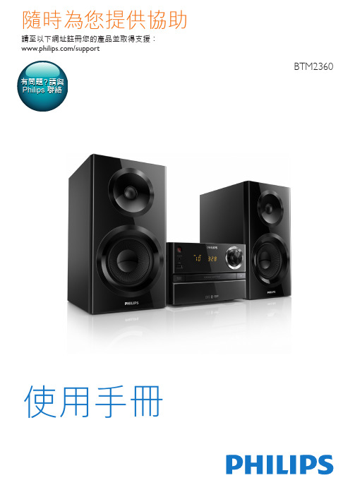
Philips BTM2360 迷你音樂系統說明書说明书
連接揚聲器
備註
•• 將每條揚聲器線的裸露部份完全插入插孔。 •• 為達到更佳的音質,僅限使用隨附的揚聲器。
1 連接右揚聲器時,找到主裝置背面標有
「R」的插孔。
2 將紅色電線插入紅色 (+) 插孔,並將黑
色電線插入黑色 (-) 插孔。
3 連接左揚聲器時,找到主裝置上標有
「L」的插孔。
4 重複步驟 2,插入左揚聲器線。
備註
•• 確定 USB 裝置中有可播放的音訊內容。
1 將 USB 裝置插入 插槽。 2 按 USB 選擇 USB 來源。
»» 隨即自動開始播放。 若沒有自動播 放,請按 。
控制播放
開始、暫停或繼續播放。 停止播放。 / 選擇專輯或資料夾。
按下可跳至上一/下一曲目。 / 按住可在曲目內倒轉/快轉搜尋。
遙控器概覽
a
b
r
c
q
p d
o
e
n
m l f
k
g
j
h
i
a • 開啟或關閉產品。 • 切換為待機模式或節能待機模式。
b CD • 選取 CD 來源。
c USB • 選擇 USB 來源。
d/ • 跳至上一/下一曲目。 • 在曲目/光碟/USB 內進行搜尋。 • 調至廣播電台。 • 調整時間。6 ZH-来自Wr • 選擇藍牙來源。
3 開始使用
注意 •• 使用本手冊以外的方法來控制、調校或不按順序
操作,可能會導致危險雷射外洩或造成其他不安 全的操作。
請務必依順序遵循本章指示。
接上電源
注意
•• 產品可能會損壞! 確定電源的電壓與產品背面或
底部所印的電壓相符。
•• 連接 AC 電源線前,請確定您已完成其他連線。
Philips SBM100 可攜式揚聲器用戶手冊说明书

6
收聽 FM 廣播
6
播放外接裝置的內容
6
透過耳機聆聽
6
調整音量
7
5 產品資訊
7
規格
7
6 疑難排解
8
7 注意
8
ZH-TW 2
1 重要事項
• 閱讀這些指示。 • 遵循所有指示。 • 請勿在近水處使用本產品。 • 請勿阻塞任何通風口。 請依照製造商
的指示進行安裝。 • 請勿將本產品安裝在接近熱源處,例如
您的產品包括了符合歐洲指令 (European Directive) 2006/66/EC 的電池,不得與其 他一般家用廢棄物一併丟棄。請注意有關 電池分類收集的當地法規,正確處理廢棄 產品有助於避免對環境和人類健康帶來負 面影響。
環境保護資訊 所有非必要之包裝材料均已捨棄。 我們嘗 試讓包裝可以輕易拆解成三種材質:厚紙 板 (外盒)、聚苯乙烯泡棉 (防震) 以及聚乙 烯 (包裝袋、保護性泡棉膠紙)。
開啟/關閉
1 將 向右滑動。 »» 揚聲器會切換至您上次選擇的來 源。
2 要關閉揚聲器,請將 向左滑動。
選擇來源
重複按 S 以選擇音訊來源:Micro SD 卡、FM 調諧器,或 Aux。
5 ZH-TW
4 播放
播放 Micro SD 卡的內容
備註 •• 確認 Micro SD 記憶卡中有可播放的音訊內容。
一般資訊
電源供應 內建電池 尺寸 - 主裝置 (寬 x 高 x 深) 重量 - 主裝置
5 V 0.6 A; 鋰電池
107 x 71 x 36 公釐 0.1 公斤
7 ZH-TW
6 疑難排解
警告
•• 請勿打開裝置外殼。
為維持有效的保固,請勿自行嘗試修理系 統。 如果您在使用本裝置時發生任何問題,請 在送修前先行檢查下列項目。 如果問題仍 未解決,請造訪 Philips 網頁 (/support)。 聯絡 Philips 時,手邊請先準備好您的裝置、型號與序 號。
VHX-1V_1BV手册V1.0
VORX TELECOMMUNICATIONS CO., LTD
-1-
北京蛙视通信技术有限责任公司
用户手册
1.概述
1.1 产品简介
HDMI/DVI 高清数字视频光端机 VHX-1V、VHX-1BV 运用先进技术,通过光纤实现对 高清数字视频信号及音频、数据的远距离传输,同时可广泛应用于广播电视,现场转播,视 频监控,安全防卫等领域。 说明: VHX-1V 为单向视频机型,视频信号输入端型号为 VHXT-1V(远端) ,视频信号输出端 型号为 VHXR-1V (中心) 。 VHXT-1V 提供输入视频信号环出接口 (该信号与输入信号相同) 。 当其它业务信号(如音频/数据等)双向传输时,需双光纤;当所有业务信号(含音频/数据 等)仅需单向传输且传输方向相同时时,为单光纤。 VHX-1BV 为双向视频机型。需双光纤。 视频输入/输出接口为 HDMI 连接器,该接口仅提供 HDMI 的视频信号传输,当所连接 的设备为 DVI 接口时,仅需配置 HDMI-DVI 转换器或转换电缆。
1.2 功能特点
1.2.1 VHX-1V 功能特点: VNX-1V 可有 2 种配置模式 【模式 1】 (默认模式) �������������������������������������������������������������������������������������������������������������������������������������������������������������������������������������������������������������������������������������������������������������������������������
NFE61PTxxx资料

For High Speed Signal
For Standard (Low DC
Resistance Type)
For Standard
0603
For High Speed Signal (Sharp impedance characteristics)
* Please see P.58 "Derating of Rated Current".
60 (0.5A) 60 (3A)
50 (3A)
60 (6A)
33 (3A) 30 (1A)
30 (3A)
33 (6A)
22 22
10 10 10
10 10
555
mm 0603 1005 1608 2012 1005 1608 2012 1608 2012
EIA Code 0201 0402 0603 0805 0402 0603 0805 0603 0805
47 47
1800
1000 (1.5A) 1000
1000
1
600 (1.5A)
600
600
470 (2A)
470
390 (2A)
390
330 (1.5A)
330
220 (2A)
220
220
180 (1.5A)
180 (3A)
120 (2A)
120 (3A)
120
120
100
80 (1A)
75 (3A)
4516 1806
1005
1608
0402
0603
GHz Range Noise GHz Range Noise Suppression Type Suppression Type BLM15H/E BLM18H/E/G
RX-V467_Manual_Chinese

自动设置扬声器参数 (YPAO)................... 23
播放
基本播放过程 ................................. 28 调节高 / 低频声音 (音调控制)................ 28
■ 与扬声器和收听环境相匹配的音响参数调节
– 扬声器音响参数的自动设置 (YPAO - Yamaha Parametric Room Acoustic Optimizer) .............................23
– 指定每个扬声器的设置 ............................................................49 – 每个扬声器的音量控制 ............................................................51 – 扬声器距离设置 ..................................................................51 – 用均衡器调节的声音质量 <Graphic Equalizer> ......................................51 – 测试音扬声器调节 ................................................................52 – 低音及高音水平调节 < 音调控制 > ..................................................28
从 iPod™/iPhone™ 播放调谐....................39 连接 Yamaha iPod 多用平台 .................... 39 控制 iPod™/iPhone™ ........................ 39