FREESCAL--LIN transciver-MC33662
Freescale msCAN教程

Nicrosystem NSCF51AC-R1开发板教程-------CAN 总线教程作者Bluehacker <QQ: 282074921> /bluehacker 版本V 1.0 日期2010年8月25日 版权说明 本教程以Nicrosystem 开发的NSCF51AC-R1型低成本飞思卡尔coldfire V1开发板为平台,但相关内容应该适用于其他公司开发的飞思卡尔coldfire V1或S08开发板,甚至对其他非飞思卡尔MCU 也有借鉴作用。
我们通过网络免费提供此教程电子版本,不收取任何费用,您可以自由下载传播,但请您不要更改本教程中的任何文字、图片、表格;更不得以任何形式声称拥有本教程的版权,侵占作者的劳动成果。
本教程可能有描述不当或错误之处,欢迎你指正,但作者和作者所在公司单位不对可能的错误负任何责任。
备注如果你发现本教程的问题,欢迎您通过 nicrosystem@ 与我们联系。
也欢迎你关注我们的产品和在电子论坛上的活动作者的博客:/bluehackerNicrosystem “我们的freescale ”专栏:/forum-100-1.htmlNicrosystem 定期在与非网社区开展系列针对飞思卡尔处理器的diy 活动和助学活动:Nicrosystem EDN “我们的freescale”小组:/2460/淘宝:一. CAN总线的特点和历史●什么是CAN?CAN,全称为“Controller Area Network”,即控制器局域网,是国际上应用最广泛的现场总线之一。
最初,CAN被设计作为汽车环境中的微控制器通讯,在车载各电子控制装置ECU 之间交换信息,形成汽车电子控制网络。
比如:发动机管理系统、变速箱控制器、仪表装备、电子主干系统中,均嵌入CAN控制装置。
一个由CAN 总线构成的单一网络中,理论上可以挂接无数个节点。
实际应用中,节点数目受网络硬件的电气特性所限制。
飞思卡尔Freescale TSS 2.5 Kinetis预览版触摸传感软件说明书
Freescale Touch Sensing Software 2.5 Kinetis PreviewRelease NotesPRODUCT: Freescale TSSPRODUCT VERSION: 2.5 Kinetis PreviewDESCRIPTION: Freescale Touch Sensing Software Library, version 2.5RELEASE DATE: November 9th 2010How to Reach Us:Home Page:Web Support:/supportUSA/Europe or Locations Not Listed: Freescale Semiconductor, Inc. Technical Information Center, EL516 2100 East Elliot RoadTempe, Arizona 852841-800-521-6274 or +1-480-768-2130 /supportEurope, Middle East, and Africa: Freescale Halbleiter Deutschland GmbH Technical Information Center Schatzbogen 781829 Muenchen, Germany+44 1296 380 456 (English)+46 8 52200080 (English)+49 89 92103 559 (German)+33 1 69 35 48 48 (French)/supportJapan:Freescale Semiconductor Japan Ltd.HeadquartersARCO Tower 15F1-8-1, Shimo-Meguro, Meguro-ku,Tokyo 153-0064Japan0120 191014 or +81 3 5437 9125***************************Asia/Pacific:Freescale Semiconductor China Ltd.Exchange Building 23FNo. 118 Jianguo RoadChaoyang DistrictBeijing 100022China+86 10 5879 8000**************************For Literature Requests Only:Freescale Semiconductor Literature Distribution Center P.O. Box 5405Denver, Colorado 802171-800-441-2447 or +1-303-675-2140Fax: +1-303-675-2150*********************************************Information in this document is provided solely to enable system and software implementers to use Freescale Semiconductor products. There are no express or implied copyright licenses granted hereunder to design or fabricate any integrated circuits or integrated circuits based on the information in this document.Freescale Semiconductor reserves the right to make changes without further notice to any products herein. Freescale Semiconductor makes no warranty, representation or guarantee regarding the suitability of its products for any particular purpose, nor does Freescale Semiconductor assume any liability arising out of the application or use of any product or circuit, and specifically disclaims any and all liability, including without limitation consequential or incidental damages. “Typical” parameters that may be provide d in Freescale Semiconductor data sheets and/or specifications can and do vary in different applications and actual performance may vary over time. All operating parameters, including “Typicals”, must be validated for each customer application by customer’s technical experts. Freescale Semiconductor does not convey any license under its patent rights nor the rights of others. Freescale Semiconductor products are not designed, intended, or authorized for use as components in systems intended for surgical implant into the body, or other applications intended to support or sustain life, or for any other application in which the failure of the Freescale Semiconductor product could create a situation where personal injury or death may occur. Should Buyer purchase or use Freescale Semiconductor products for any such unintended or unauthorized application, Buyer shall indemnify and hold Freescale Semiconductor and its officers, employees, subsidiaries, affiliates, and distributors harmless against all claims, costs, damages, and expenses, and reasonable attorney fees arising out of, directly or indirectly, any claim of personal injury or death associated with such unintended or unauthorized use, even if such claim alleges that Freescale Semiconductor was negligent regarding the design or manufacture of the part.Freescale™ and the Freescale logo are trademarks of Freescale SemiconductorAll other product or service names are the property of their respective owners. © Freescale Semiconductor, Inc. 2009. All rights reserved.Rev. 611/2010Table of Contents1 Introduction (3)1.1 Requirements (3)1.1.1 System Requirements (3)1.1.2 Target Requirements (3)1.2 Special Instructions (4)1.2.1 Installation Instructions (4)2 Release Content (5)2.1 Example Applications (5)3 New Features (6)4 Release Description (7)4.1 Supported Features (7)4.2 Limitations (7)5 Release History (8)1 IntroductionThis document describes the Freescale Touch Sensing Software (TSS) version 2.5 released for ARM®Cortex™-M4 Kinetis processor family.This is the preview version of the TSS 2.5 library for the Kinetis family. It is based on and is backward compatible with TSS version 2.0. The features described here are not ported back to HCS08 and ColdFire® V1 platforms. A full TSS 2.5 release will bring the new library features to all Kinetis, HCS08, and ColdFire® V1 platforms.1.1 Requirements1.1.1 System RequirementsThe ARM®Cortex™-M4 version of the library was developed, compiled and tested with IAR Embedded Workbench for ARM Version 5.50.6 and Version 6.10.The system requirements are defined by the development tools requirements. There are no special host system requirements for hosting the Freescale TSS distribution.Minimum PC configuration:▪As required by CodeWarrior® Development StudioRecommended PC configuration:▪ 2 GHz processor – 2 GB RAM - 2 GB free disk spaceSoftware requirements:▪OS: As required by development tools (Windows XP SP2 or later recommended)1.1.2 Target RequirementsThe Freescale TSS in this release supports the ARM®Cortex™-M4 families of microcontrollers. The requirements for the target hardware are same as the operating requirement of your evaluation or custom board (power supply, cabling, jumper settings etc).There are physical parameters that directly affect the Touch Sensing performance like electrodes design, PCB routing, parasitic capacitance at processor pins etc. Refer to appropriate Application Notes related to the software-based capacitive measurements available on/touchsensing .This release of Freescale TSS contains application examples for the following boards:TWR-K60N512 Tower board with MK60N512TWR-K40X256 Tower board with MK40X256The boards are available for purchase at Freescale web site.1.2 Special Instructions1.2.1 Installation InstructionsRun the self-extracting executable and proceed according to instructions on the screen. Refer to Touch Sensing Software User Guide available in the Start/Programs menu after installation.2 Release ContentThis is release version 2.5 of the Freescale Touch Sensing Software. The content is described in the following table.The following picture shows the Freescale TSS directories installed to the user host computer:2.1 Example ApplicationsExample applications are included in the library distribution in the examples folder.- twrk60n512 demo application for the TWR-K60N512 board servicing all four electrodes ofthe board and demonstrating use of Keypad decoder. TSI module is used for electrode sensing. Touch status of each electrode is indicated by LED placed inside the electrode area. The application is available in the /examples/TWRKXX_DEMO folder. - twrk40x256 demo application for the TWR-K40X256 board servicing all four electrodes ofthe board and demonstrating use of Keypad decoder. TSI module is used for electrode sensing. Touch status of each electrode is indicated by LED placed inside the electrode area. The application is available in the /examples/TWRKXX_DEMO folder.--- Documentation--- Configuration examples and example applications--- TSS Library Files --- PC Host Tools3 New FeaturesFreescale is committed to maintain this product and to deliver updates and enhancements timely. This section describes the major changes and new features implemented in this release.In comparison to version 2.0, the TSS 2.5 Kinetis Preview release implements the following features:-TSS Libraryo ARM®Cortex™-M4 support added. The TSS_ARM.a precompiled library for ARM®Cortex™-M4 was added into the lib directory.o Touch Sense Input (TSI) hardware module added. The module enables robust hardware-driven capacitance measurements to be performed without CPU intervention.The TSS library has been reworked to enable such a “background” processing andsave CPU time and power consumption.o GPIO (ATL, CTS) and other low-level layer sensing algorithms are still available in the TSS library and may be used to detect touch on electrodes connected to non-TSI pins.o TSI active mode clock configuration parameters added into the TSS_SystemSetup.h file.o TSI bit-resolution parameter (TSS_TSI_RESOLUTION) added into theTSS_SystemSetup.h file. The TSS code automatically manages the TSI moduleruntime configuration to achieve the desired resolution.o ATL and CTS low-level layer sensing algorithms are no longer mutually exclusive. The CTS method can be applied to the selected electrodes just like an ordinary methodadditional to GPIO, TSI, and other. The electrode type is set up in theTSS_SystemSetup.h file.o The TSS low-level layer now enables to use the following methods: GPIO, CTS and TSI. The other methods (PTI, KBI, TPM, FTM) known from TSS 2.0 will be supported inthe follow up library version. Selection of the electrode type is performed inTSS_SystemSetup.h by the TSS_En_Type macro.o Various trigger mechanisms are added. A new automatic trigger may help to achieve periodic electrode sampling and let the TSI module to drive the period also for non-TSIelectrodes. In addition to the automatic trigger, two manual triggers may be used toreduce complexity of conditional execution of TSS_Task when any kind of periodicity isrequired.o Source code files are renamed and the code is refactored:-A TL_SENSOR_TIMEOUT and ATL_SENSOR_PRESCALER macros a renamed toTSS_SENSOR_TIMEOUT and TSS_SENSOR_PRESCALER.-A TL_Timer.h file renamed to TSS_Timer.h file.-M acros with ATL_HW_TIMER_ prefix were renamed to use TSS_HW_TIMER_prefix in TSS_Timer.h file.-A TL_Sensor.h and ATL_Sensor.c files renamed to TSS_Sensor.h andTSS_Sensor.c.-I nterrupt handlers for the low level layer methods moved to the appropriateTSS_SensorXXX.c which enables to assign interrupt vector number automatically.4 Release Description4.1 Supported Features-TSI HW module support for ARM®Cortex™-M4 Kinetis processors.-Software-only capacitive touch sensing for. ARM®Cortex™-M4 Kinetis processors.-Backward compatibility with TSS 1.x and 2.0.-Easy to use and integrate with existing user applications.-Electrode malfunction detection.-Support for up to 64 electrodes.-Compile-time configurable using a single header file (at user application level).-Graphical System Setup Creator utility to help creating the configuration header file.-Several touch-detection and capacity measurement algorithms available:o TSI, GPIO, CTS.-Advanced Key Detector signal processing layer.-Decoded signals available to user application.-Easy to use decoding structures with callback event notification.o Keypad – keyboard decoder supporting multiple key press and auto-repeat.o Slider – handling linearly distributed electrodes as a single up-down or left-right control.o Rotary – handling ring-distributed electrodes as a single jog-dial-like control.-Supports up to 16 instances of decoding controls.4.2 Limitations-This is the Kinetis Preview version of the library only. New features are not available to HCS08 and ColdFire® V1 platforms.-TSI and GPIO are the only available sampling methods. The pin interrupt and timer input capture methods will be implemented in the future library version.-Advanced Low Power and Wake-up features of the TSI module are not enabled in the current library version.5 Release HistoryVersion 1.0 (September 21st 2009)-First public release of the library with an example for LG32-based TSSEVB Rev.B evaluation board.Version 1.1 (January 27th 2010)-TSS.libo Baseline Tracking bug fixed. The baseline was updated slowly in case of negative delta value.o TSS_ERROR_KEYPAD_NOT_IDLE state removed from TSS Keypad Decoder.o DC Tracker init value changed from 64 to 100.o Number of CTS measurements allowed to be interrupted by user application before a timeout occurs was increased from 20 to 128.o Setting the System Reset bit in the TSS System Configuration Register makes TSS to restart immediately.o atl_u8SampleIntFlag variable definition moved from ATL_Sensor.h to C code.-TSSEVB_SINGLE application exampleo I2CDvr.c file updated so the sensitivity can be set from EGT.-TSSEVB_DEMO application exampleo I2CDvr.c file updated so the sensitivity can be set from EGT.o BUSclk changed to 20 MHz if CTS sensing algorithm selected. This enhances algorithm sensitivity.o SCI baud rate setting fixed since 20MHz bus clock is used with CTS sensing algorithm selected. Needed to properly communicate with COMM JM60 device.o Electrodes Sensitivity changed for Washing Machine demo application if CTS sensing algorithm selectedVersion 2.0 (August 23rd 2010)o ColdFire® V1 support added. The TSS.lib precompiled library for HCS08 family was renamed to TSS_S08.lib and the TSS_CFV1.a precompiled library for ColdFire® V1was added into the same directory.o The IIR filter feature was implemented at the Key detector level. The filter processes capacitance values obtained from low-level routines and works with both ATL and CTSalgorithms. Use of this feature is optional, enable it in TSS_SystemSetup.h.o The Noise Amplitude Filter function was implemented in the ATL and CTS low level.The user can define the noise amplitude to be filtered. Noise peaks greater than thedefined amplitude are filtered by the system, thus disregarding the noisy sample. Useof this feature is optional; enable it in TSS_SystemSetup.h together with setting theNoise Amplitude Filter sizes for each electrode.o The SWI feature which can be enabled in the TSS registers is available only for HCS08 version of the TSS library. The OnFault callback feature was added to enable handlingof a fault situation on both HCS08 and ColdFire® V1 processors. Specify name ofapplication callback function as the TSS_ONFAULT_CALLBACK parameter in theTSS_SystemSetup.h file.o Baseline balancing algorithm was simplified in the Key detector code.o The ATL low level layer now enables to use also GPIO Port Interrupt, KBI and TPM Input Capture modules to improve sensitivity. Use of this feature is optional, enable it in TSS_SystemSetup.h.o New TSS_Task “sequencing” feature enables to divide task processing to several steps where each electrode is acquired in separate TSS_TaskSeq call. When all electrodesare processed, the decoders are handled all at once in the last TSS_TaskSeq call.o Default electrode pin state was changed to logic-high when measurement is idle. This helps to achieve lower power consumption in low power modes. The only exception isthat a pin is set to logic-low state when timer timeout occurs (electrode charge timeout).Timeout may be a symptom of short-grounded electrode, so setting the output pin tologic low prevents high current sourced from pin and achieves lower powerconsumption.o ATL_SENSOR_TIMEOUT and ATL_SENSOR_PRESCALER macros were moved to TSS_SystemSetup.h and are now configurable. Default value ofATL_SENSOR_TIMEOUT was set to 511, ATL_SENSOR_PRESCALER was set to 2.o Macros with ATL_TIMER_ prefix were renamed to use ATL_HW_TIMER_ prefix in ATL_Timer.h in order to differentiate it from ATL_IC_TIMER_macros used for TimerInput Capture method.o ATL HW Timer Interrupt handler moved from inside of library to the ATL_Sensor.c which enables to assign interrupt vector number automatically.o GPIO Pin Interrupt-based measurement method added.o FTM timer support added.o The type of ATL Low Level routine return value was changed from UINT8 to UINT16, making it more general for large capacitance differences between electrodes.o The ATL_ElectrodesSetState function code was reduced in size and was renamed to ATL_ElectrodesSetStateHigh. The function now only sets all electrodes to logic output-high state as this is the only stat really used.o Checking of Fault timeout and the u8FaultCnt counter variable was added to ATL_SampleElectrode function. The timeout is set by macro ATL_FAULT_TIMEOUT in ATL_Sensor.h.o Fixed issues:-When more than seven controls were used, the tss_cau8BuffMask[] array inTSS_SystemSetupData.c was not defined properly.-Removed warning messages when no control is used. The tss_pau8EventsBuff[] andtss_acpsCSStructs[] arrays were not correctly defined in TSS_SystemSetupData.c.-Removed redundant Warning messages if Slew Rate and Strength registers do notexist.-TSSEVB_SINGLE application exampleFreescale TSS Release NotesFreescale Semiconductor 10 o ATL_SENSOR_TIMEOUT and ATL_SENSOR_PRESCALER macros were moved toTSS_SystemSetup.h. Macro ATL_HW_TIMER_TIMEOUT set to 1023,ATL_SENSOR_PRESCALER set to 2.o ATL_TimerIsr vector assignment removed from .prm file. This is now doneautomatically by the TSS library code.- TSSEVB_DEMO application exampleo ATL_SENSOR_TIMEOUT and ATL_SENSOR_PRESCALER macros were moved toTSS_SystemSetup.h. Macro ATL_HW_TIMER_TIMEOUT set to 1023,ATL_SENSOR_PRESCALER set to 2.o ATL_TimerIsr vector assignment removed from .prm file. This is now doneautomatically by the TSS library code.o Electrode pins where an alternative KBI or TPM channel feature is available werereconfigured in TSS_SystemSetup.h to use new type of measurement.- Processor Expert supportProcessor Expert TSS Component v1.0 included in the form of PEupd package. Thecomponent may help to configure the TSS library in an easy to use graphical environment.Version 2.5 (Kinetis Preview 9th 2010)- TSI module added.- Library implementation for the ARM ®Cortex™-M4 Kinetis processor family.- Demo applications provided for TWR-K60n512 and TWR-K40x256 boards. For details, referto New Features .。
卡林技术公司产品说明书

UL Recognized UL Standard 1077Component Recognition Program as Protectors,Supplementary (Guide QVNU2,File E75596)UL Standard 508Switches,Industrial Control (Guide NRNT2,File E148683)CSA CertifiedComponent Supplementary Protector under Class 3215 30,FIle 047848 0 000CSA Standard C22.2 No. 235VDE CertifiedEN60934,VDE 0642 under File No.10537Agency CertificationsNotes for T able A:1DC and 1Ø 277 Volt ratings are 1 or 2 poles breaking. 3Ø Ratings are 3 poles breaking.2 Requires branch circuit backup with a UL LISTED Type K5 or RK5 fuse rated 15A minimum and no more than 4 times full load amps not to exceed 150A for 250 Volt rating and 125A for 277and 480 Volt ratings.3 UL Recognition and CSA Certification at 480 Volts refers to 3 and 4 pole versions, used only in a 3Ø wye connected circuit or 2 pole versions connected with 2 poles breaking 1Ø and backedup with series fusing per note 2.Table A:Lists UL Recognized and CSA and VDE Certified configurations and performance capabilities as a Component Supplementary Protector.ElectricalCURRENT RA TINGCIRCUITMAX FULL LOAD WITH WITHOUT (Inc) WITH (Icn) WITHOUTCONFIGURA TIONRA TINGFREQUENCYPHASEAMPSBACKUP FUSEBACKUP FUSEBACKUP FUSEBACKUP FUSE65DC ---0.02 - 50 ---500050001500125/25050/60 1 and 30.02 - 50 ---3000 --- ---25050/60 1 and 30.02 - 505000 ---5000150027750/6010.02 - 505000 --- --- ---480 Y 50/60 1 and 30.02 - 305000---------65DC ---0.02 - 5025050/60 1 and 30.02 - 5027750/6010.02 - 50480 Y50/6030.02 - 30480 Y 50/6010.02 - 30SWITCH ONL Y UL / CSAVDED-SERIES TABLE A: COMPONENT SUPPLEMENTARY PROTECTORVOLT AGEINTERRUPTING CAPACITY (AMPS)SERIESDesigned for snap-on-back panel rail mounting on either a 35mm x 7.5mm, or a 35mm x 15mm Symmetrical Din Rail,allowing rapid and simple mounting and removal of the breaker.It features recessed, wire-ready, touch-proof, shock-resistant ter-minals, suitable for automatic screwdriver assembly, as well as "Dead Front" construction characteristics.Available with a Visi-Rocker two-color actuator, which can be specified to indicate either the ON or the TRIPPED/OFF mode,or solid color rocker or handle type actuators. All actuator types fit in the same industry standard panel cutouts.0.02 - 50 amps, up to 480 VAC or 65 VDC, 1 - 4 poles (Handle),1 - 3 poles (Rocker), with a choice of time delays.Number of PolesRocker Type: 1-3; Handle Type: 1-4 Internal Circuit Config. Switch Only and Series Trip with cur-rent or voltage trip coils.WeighApproximately 128 grams/pole (Approximately 4.57 ounces/pole)Standard Colors Housing - Black; Actuator - See Ordering Scheme.MountingMounts on a standard 35mmSymmetrical DIN Rail (35 x 7.5 or 35x 15mm per DIN EN5002).MechanicalElectricalPhysicalEndurance10,000 ON-OFF operations @ 6 per minute; with rated Current and Voltage.Trip FreeAll D-Series Circuit Breakers will trip on overload,even when actuator is forcibly held in the ON position.Trip IndicationThe operating actuator moves posi-tively to the OFF position when an overload causes the breaker to trip.Designed and tested in accordance with requirements of specifi-cation MIL-PRF-55629 & MIL-STD-202 as follows:Shock Withstands 100 Gs,6ms,sawtoothwhile carrying rated current per Method 213,Test Condition "I".Instantaneous and ultra-short curves tested @ 90% of rated current.Vibration Withstands 0.060" excursion from10-55 Hz,and 10 Gs 55-500 Hz,at rated current per Method 204C,Test Condition A. Instantaneous and ultra-short curves tested at 90% of rated current.Moisture Resistance Method 106D,i.e.,ten 24-hourcycles @ + 25°C to +65°C,80-98%RH.Salt Spray Method 101,Condition A (90-95%RH @ 5% NaCl Solution,96 hrs).Thermal Shock Method 107D,Condition A (Fivecycles @ -55°C to +25°C to +85°C to +25°C).Operating Temperature -40°C to +85°CEnvironmental020 0.0200250.0250300.0300500.050075 0.0750800.0800850.0852100.1002150.1502200.2002250.2502300.3002350.3502400.4002450.450250 0.5002550.5502600.6002650.6502700.7002750.7502800.8002850.850410 1.000512 1.250413 1.300414 1.400415 1.500517 1.750420 2.000522 2.250425 2.500527 2.750430 3.000532 3.250435 3.500436 3.600440 4.000445 4.500547 4.750450 5.000455 5.500460 6.000465 6.5004707.0005727.2504757.5004808.0004858.5004909.0004959.500610 10.00071010.50061111.00071111.50061212.00071212.50061313.00061414.000615 15.00061616.00061717.00061818.00061919.00062020.00062121.00062222.000623 23.00062424.00062525.00062626.00062727.00062828.00062929.00063030.00063232.00063535.00064040.00064545.00065050.000A06 6 DC, 5 DC A1212 DC, 10 DC A1818 DC, 15 DC A2424 DC, 20 DC A3232 DC, 25 DC A4848 DC, 40 DC A6565 DC, 55 DC J06 6 AC, 5 AC J1212 AC, 10 AC J1818 AC, 15 ACJ2424 AC, 20 AC J4848 AC, 40 AC K20120 AC, 65 AC L40240 AC, 130 AC10Agency Approval8Actuator Color8 ACTUATOR COLOR & LEGEND Actuator orVisi-Color Marking: Marking Color: Single Color Visi-Rocker Color:I-O ON-OFF Dual Rocker/Handle (Actuator Black)8White A B 1Black White Black C D 2White n/a Red F G 3White Red Green H J 4White Green Blue K L 5White Blue Y ellow M N 6Black Y ellow Gray P Q 7Black Gray OrangeRS8Black Orange10 AGENCY APPROVAL C UL Recognized & CSA Certified D VDE Certified, UL Recognized & CSA Certified9 MOUNTING/VOLTAGEMOUNTING STYLE VOLTAGE Threaded Insert 16-32 x 0.195 inches< 300C 96-32 X 0.195 inches ≥300 2ISO M3 x 5mm< 300D 9ISO M3 x 5mm ≥3007 TERMINAL1#10 Screw & Pressure Plate for Direct Wire Connection 2#10 Screw without Pressure Plate3 POLES 1One2Two 3Three4Four5 FREQUENCY & DELA Y 03DC 50/60Hz, Switch Only 105DC Instantaneous 11DC Ultra Short 12DC Short 14DC Medium 16DC Long20550/60Hz Instantaneous 2150/60Hz Ultra Short 2250/60Hz Short 2450/60Hz Medium2650/60Hz Long32DC, 50/60Hz Short 34DC, 50/60Hz Medium 36DC, 50/60Hz Long42650/60Hz Short, Hi-Inrush 44650/60Hz Medium, Hi-Inrush 46650/60Hz Long, Hi-Inrush 527DC, Short,Hi-Inrush 547DC,Medium, Hi-Inrush 567DC, Long, Hi-Inrush4 CIRCUITA0 Switch Only (No Coil) 4B0Series Trip (Current)C0Series Trip (Voltage)1 SERIES D6Current Rating4Circuit3Poles2Actuator9Mounting/Voltage7Terminal5Frequency & Delay1SeriesNotes:1 Handle breakers available up to four poles. Rocker breakers available up to three poles.2Actuator Code:A: Multi-pole units factory assembled with common handle tie.B: Handle location as viewed from front of breaker:2 pole - left pole3 pole - center pole4 pole - two handles at center poles3Multipole rocker breakers have one rocker per breaker, as viewed from the front of thepanel. Two pole - left pole. Three pole - center pole 4≤30A, select Current Rating code 630. 31-50A, select Current Rating code 650.5Voltage coil only available with delay codes 10 & 20.6Available to 50A max with circuit code BO only.7Available to 50A (UL/CSA), 30A (VDE) with circuit code BO only.8Color shown is visi and legend with remainder of rocker black.9≥300V: Three pole breaker 3Ø or 2 pole breaker 1Ø, UL/CSA limited to 30 FLA max.10VDE Approval requires Dual (I-O, ON-OFF) or I-O markings6 CURRENT RATING (AMPERES)OR VOLTAGE COIL (VOLTS, MIN. TRIP RATING)5P0LE 3P0LE 2P0LE 1SERIES TRIP (2 TERM'S.)LINELINEROCKER ACTUATOR INDICATE "ON"HANDLE ACTUATORSWITCH ONL Y (2 TERM'S.)#10-32 SCREW AND PRESSURE PLA TE PER TERMINAL"MULTI-POLE IDENTIFICATION SCHEMENotes:1All dimensions are in inches [millimeters].2T olerance ±.015 [.38] unless otherwise specified.3-POLE(DF3) 3-POLE(DC3)REMOVALASSEMBL YNotes:1All dimensions are in inches [millimeters].2T olerance ±.015 [.38] unless otherwise specified.3Dimensions apply to all variations shown. Notice that circuit breaker line and load termi-nal orientation on indicate OFF is opposite of indicate ON.4For pole orientation with horizontal legend, rotate front view clockwise 90°.Notes:1All dimensions are in inches [millimeters].2T olerance ±.010 [.25] unless otherwise specified.。
LIN总线物理接口器件MC33399的原理及应用说课讲解

L I N总线物理接口器件M C33399的原理及应用LIN总线物理接口器件MC33399的原理及应用摘要:MC33399是Frescale公司推出的汽车LIN总线单线物理接口器件。
文中详细介绍了MC33399的主要功能、内部结构以及工作原理,并在此基础上给出了MC33399的典型应用电路。
关键词:MC33399 LIN总线汽车电子1 概述LIN(Local Interconnect Network局域互连网络)是一种低成本的总线网络。
其最初的开发目的在于弥补CAN总线的不足,主要用于汽车中某些对通信速率要求不高的场合,LIN总线作为CAN总线的辅助网络或子网络使用可以解决汽车内因导线过多所带来的许多问题。
一个简单的LIN节点除了微控制器外,还需要两个芯片,即LIN接口芯片和5V 的电压调节器。
Freescale公司的MC33399芯片是专用于LIN的单线物理接口器件。
该器件的功耗非常低,可控制外部稳压器,安全符合LIN规范,抗干扰能力强,是一种高性能的模拟器件,适用于工作环境比较复杂的汽车。
MC33399的主要特点如下:·通信速率范围为1~20kb/s;·额定工作电压:8V~18V,正常电压:7V~27V;·无功节点不影响总线状态;·有正常和睡眠两种工作模式,睡眠模式下的静态电流仅20μA;·LIN总线唤醒、MCU命令唤醒以及接口外部高压开关输入唤醒;·通过兼容的CMOS I/O脚与MCU进行接口;·带有外部稳压器控制功能;·内置上拉电阻;·LIN引脚的ESD电压可达4kV;·具有很好的电磁兼容性;·工作温度范围为-40℃~125℃。
2 引脚功能MC33399采用SO8型贴片式封装。
图1示出引脚排列,各引脚的功能说明如表1所列。
表1 MC33399的引脚功能引脚号引脚名功能1 RX 接收数据输出端2 EN 使能端3 Wake 唤醒端,用于将芯片从睡眠中唤醒4 TX 发送数据输入端5 GND 电源地6 LIN LIN总线接口端7 Vsup 电源8 INH 外部稳压器控制端3 内部结构及工作原理MC33399的内部结构框图如图2所示。
飞思卡半导体 微控制器系列MC9S08QE128 8位 產品說明書

目標應用• 健康監測儀器• 中央空調及樓宇控制 • 煤氣表、水錶及暖氣表• 監控攝像機 • 數碼相機• 測量設備概述Flexis TM 系列控制器是“飛思卡爾控制器聯合體”(Freescale Controller Continuum)中的連接點,它使8位和32位產品的兼容成為現實。
Flexis系列包括可相互替換的8位S08和32位ColdFire ® V1微控制器系列產品,它們采用相同的外圍設備和開發工具,從而可以提供最大的移植靈活性。
QE系列產品由一對器件組成,它們管腳兼容,一個是8位,另一個是32位;它是Flexis系列中的首個產品族。
S08QE128器件拓展了8位微處理器的性能,達到128KB的閃存和24通道的12位模數轉換器(ADC)。
S08QE128還有高達3.6V的電源電壓、50 MHz的CPU內核和三個定時器,可改善電機控制性能,非常適用于健康監測儀器及其他電子產品,如數碼相機和網絡攝像頭等。
8位的S08QE128在管腳、外圍設備和工具等各方面都與32位的MCF51QE128互相兼容,這為它們的各方面性能都提供了前所未有的設計自由度。
Flexis TM 微控制器系列MC9S08QE1288位產品說明書使用外圍設備長電池使用壽命• 新的ULP電源等待模式• Stop3模式下6 µs的典型喚醒時間• 由內部或外部參考時鐘控制,包含鎖頻環(FLL)的內部時鐘源(ICS)模塊• 無需使用外部時鐘源。
這將從根本上降低系統開發成本。
• 閉環控制皮爾斯振蕩器(OSC);31.25 kHz到38.4kHz或1 MHz到16 MHz的晶振或陶瓷振蕩器• 具有在低功耗模式下提供精確時基的超低功耗振蕩器Freescale TM 和Freescale標識是飛思卡爾半導體公司的注冊商標。
所有其它產品和服務的名稱均為各自所有者的財產。
©飛思卡爾半導體公司2007年版權所有。
文件編號:MC9S08QE128FSREV 0• • 相同的硬件連接器• 斷點設置• 在線調試過程中可設置一個斷點設置(外加內置調試模塊中的另三個斷點)• 包含三個比較器和九種觸發方式的ICE調試模塊。
液晶弹性体

3. Actuators based on LCEs
3.1. Actuators based on thermally actuated LCEs
Fig 3. Micrometer-sized nematic LCE actuators consisting of a pillar array. (a) Experimental setup used to prepare the responsive pillars. (b) Top view (under an optical microscope) of the pillar pattern obtained by the imprint in the nematic liquid crystal elastomer. (Inset) Zoom on the structure (pillar diameter=20mm)[1]. [1 ]Buguin A, Li M H, Silberzan P, et al. Journal of the American Chemical Society, 2006, 128(4): 1088-1089.
4. Summary
1.Introduction
Smart materials:
There is a group of materials capable of responding to external stimuli with mechanical deformation.
Fig 1. The diferent kinds of actuator materials both in natural and synthetic systems
3. Actuators based on LCEs
MC3361-中频接收IC
电特性
静态电流(无信号)
音频输出电压 输入限幅电压 失真度 录音输出噪声电压 电压下降 AF 增益损耗 检波输出电阻 信噪比 滤波器增益 滤波器输出直流电压 静噪低阻抗 静噪高阻抗 扫描控制低电平 扫描控制高电平 触发迟滞 混频器转换增益 混频器输入电阻 混频器输入电容
符号 ICC1 ICC2 VOUT VIN(Lim) THD VNO ∆Gv ROUT S/N Gv VO(DC) RON(Mute) ROff(Mute) VL(Scan) VH(Scan) VTH GV(Mix) Ri(Mix) Ci(Mix)
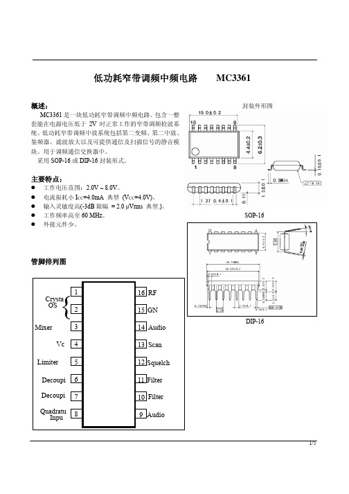
低功耗窄带调频中频电路 MC3361
概述:
MC3361 是一块低功耗窄带调频中频电路。包含一整 套能在电源电压低于 2V 时正常工作的窄带调频检波系 统。低功耗窄带调频中放系统包括第二变频、第二中放、 鉴频器、滤波放大以及可提供通信及扫描信号的静音模 块。用于调频通信交换器中。
采用 SOP-16 或 DIP-16 封装形式。
1 0. 2 45 MHz
CFU 455D
Vc c
220pF FL1 0 . 1u F
50K 0 . 1u F
52K 20K 0 . 1u F
3/5
应用图
MC3361
特性曲线
4/5
MC3361
5/5
电特性
符号 Vcc(MAX)
Vcc VIN(DET) VIN(RF) VMUTE
Topr Tstg
数值 10
2.0~8.0 1.0 1.0
-0.5~+5.0 -20~+70 -65~150
单位 V V
Vp-p Vrms Vpeak
°C °C
电特性 (若无其它规定,Ta=25°C, Vcc=4V, fo=10.7MHz, fm=1kHz, ∆f=±3kHz)
Native Instruments MASCHINE MIKRO MK3用户手册说明书
The information in this document is subject to change without notice and does not represent a commitment on the part of Native Instruments GmbH. The software described by this docu-ment is subject to a License Agreement and may not be copied to other media. No part of this publication may be copied, reproduced or otherwise transmitted or recorded, for any purpose, without prior written permission by Native Instruments GmbH, hereinafter referred to as Native Instruments.“Native Instruments”, “NI” and associated logos are (registered) trademarks of Native Instru-ments GmbH.ASIO, VST, HALion and Cubase are registered trademarks of Steinberg Media Technologies GmbH.All other product and company names are trademarks™ or registered® trademarks of their re-spective holders. Use of them does not imply any affiliation with or endorsement by them.Document authored by: David Gover and Nico Sidi.Software version: 2.8 (02/2019)Hardware version: MASCHINE MIKRO MK3Special thanks to the Beta Test Team, who were invaluable not just in tracking down bugs, but in making this a better product.NATIVE INSTRUMENTS GmbH Schlesische Str. 29-30D-10997 Berlin Germanywww.native-instruments.de NATIVE INSTRUMENTS North America, Inc. 6725 Sunset Boulevard5th FloorLos Angeles, CA 90028USANATIVE INSTRUMENTS K.K.YO Building 3FJingumae 6-7-15, Shibuya-ku, Tokyo 150-0001Japanwww.native-instruments.co.jp NATIVE INSTRUMENTS UK Limited 18 Phipp StreetLondon EC2A 4NUUKNATIVE INSTRUMENTS FRANCE SARL 113 Rue Saint-Maur75011 ParisFrance SHENZHEN NATIVE INSTRUMENTS COMPANY Limited 5F, Shenzhen Zimao Center111 Taizi Road, Nanshan District, Shenzhen, GuangdongChina© NATIVE INSTRUMENTS GmbH, 2019. All rights reserved.Table of Contents1Welcome to MASCHINE (23)1.1MASCHINE Documentation (24)1.2Document Conventions (25)1.3New Features in MASCHINE 2.8 (26)1.4New Features in MASCHINE 2.7.10 (28)1.5New Features in MASCHINE 2.7.8 (29)1.6New Features in MASCHINE 2.7.7 (29)1.7New Features in MASCHINE 2.7.4 (31)1.8New Features in MASCHINE 2.7.3 (33)2Quick Reference (35)2.1MASCHINE Project Overview (35)2.1.1Sound Content (35)2.1.2Arrangement (37)2.2MASCHINE Hardware Overview (40)2.2.1MASCHINE MIKRO Hardware Overview (40)2.2.1.1Browser Section (41)2.2.1.2Edit Section (42)2.2.1.3Performance Section (43)2.2.1.4Transport Section (45)2.2.1.5Pad Section (46)2.2.1.6Rear Panel (50)2.3MASCHINE Software Overview (51)2.3.1Header (52)2.3.2Browser (54)2.3.3Arranger (56)2.3.4Control Area (59)2.3.5Pattern Editor (60)3Basic Concepts (62)3.1Important Names and Concepts (62)3.2Adjusting the MASCHINE User Interface (65)3.2.1Adjusting the Size of the Interface (65)3.2.2Switching between Ideas View and Song View (66)3.2.3Showing/Hiding the Browser (67)3.2.4Showing/Hiding the Control Lane (67)3.3Common Operations (68)3.3.1Adjusting Volume, Swing, and Tempo (68)3.3.2Undo/Redo (71)3.3.3Focusing on a Group or a Sound (73)3.3.4Switching Between the Master, Group, and Sound Level (77)3.3.5Navigating Channel Properties, Plug-ins, and Parameter Pages in the Control Area.773.3.6Navigating the Software Using the Controller (82)3.3.7Using Two or More Hardware Controllers (82)3.3.8Loading a Recent Project from the Controller (84)3.4Native Kontrol Standard (85)3.5Stand-Alone and Plug-in Mode (86)3.5.1Differences between Stand-Alone and Plug-in Mode (86)3.5.2Switching Instances (88)3.6Preferences (88)3.6.1Preferences – General Page (89)3.6.2Preferences – Audio Page (93)3.6.3Preferences – MIDI Page (95)3.6.4Preferences – Default Page (97)3.6.5Preferences – Library Page (101)3.6.6Preferences – Plug-ins Page (109)3.6.7Preferences – Hardware Page (114)3.6.8Preferences – Colors Page (114)3.7Integrating MASCHINE into a MIDI Setup (117)3.7.1Connecting External MIDI Equipment (117)3.7.2Sync to External MIDI Clock (117)3.7.3Send MIDI Clock (118)3.7.4Using MIDI Mode (119)3.8Syncing MASCHINE using Ableton Link (120)3.8.1Connecting to a Network (121)3.8.2Joining and Leaving a Link Session (121)4Browser (123)4.1Browser Basics (123)4.1.1The MASCHINE Library (123)4.1.2Browsing the Library vs. Browsing Your Hard Disks (124)4.2Searching and Loading Files from the Library (125)4.2.1Overview of the Library Pane (125)4.2.2Selecting or Loading a Product and Selecting a Bank from the Browser (128)4.2.3Selecting a Product Category, a Product, a Bank, and a Sub-Bank (133)4.2.3.1Selecting a Product Category, a Product, a Bank, and a Sub-Bank on theController (137)4.2.4Selecting a File Type (137)4.2.5Choosing Between Factory and User Content (138)4.2.6Selecting Type and Character Tags (138)4.2.7Performing a Text Search (142)4.2.8Loading a File from the Result List (143)4.3Additional Browsing Tools (148)4.3.1Loading the Selected Files Automatically (148)4.3.2Auditioning Instrument Presets (149)4.3.3Auditioning Samples (150)4.3.4Loading Groups with Patterns (150)4.3.5Loading Groups with Routing (151)4.3.6Displaying File Information (151)4.4Using Favorites in the Browser (152)4.5Editing the Files’ Tags and Properties (155)4.5.1Attribute Editor Basics (155)4.5.2The Bank Page (157)4.5.3The Types and Characters Pages (157)4.5.4The Properties Page (160)4.6Loading and Importing Files from Your File System (161)4.6.1Overview of the FILES Pane (161)4.6.2Using Favorites (163)4.6.3Using the Location Bar (164)4.6.4Navigating to Recent Locations (165)4.6.5Using the Result List (166)4.6.6Importing Files to the MASCHINE Library (169)4.7Locating Missing Samples (171)4.8Using Quick Browse (173)5Managing Sounds, Groups, and Your Project (175)5.1Overview of the Sounds, Groups, and Master (175)5.1.1The Sound, Group, and Master Channels (176)5.1.2Similarities and Differences in Handling Sounds and Groups (177)5.1.3Selecting Multiple Sounds or Groups (178)5.2Managing Sounds (181)5.2.1Loading Sounds (183)5.2.2Pre-listening to Sounds (184)5.2.3Renaming Sound Slots (185)5.2.4Changing the Sound’s Color (186)5.2.5Saving Sounds (187)5.2.6Copying and Pasting Sounds (189)5.2.7Moving Sounds (192)5.2.8Resetting Sound Slots (193)5.3Managing Groups (194)5.3.1Creating Groups (196)5.3.2Loading Groups (197)5.3.3Renaming Groups (198)5.3.4Changing the Group’s Color (199)5.3.5Saving Groups (200)5.3.6Copying and Pasting Groups (202)5.3.7Reordering Groups (206)5.3.8Deleting Groups (207)5.4Exporting MASCHINE Objects and Audio (208)5.4.1Saving a Group with its Samples (208)5.4.2Saving a Project with its Samples (210)5.4.3Exporting Audio (212)5.5Importing Third-Party File Formats (218)5.5.1Loading REX Files into Sound Slots (218)5.5.2Importing MPC Programs to Groups (219)6Playing on the Controller (223)6.1Adjusting the Pads (223)6.1.1The Pad View in the Software (223)6.1.2Choosing a Pad Input Mode (225)6.1.3Adjusting the Base Key (226)6.2Adjusting the Key, Choke, and Link Parameters for Multiple Sounds (227)6.3Playing Tools (229)6.3.1Mute and Solo (229)6.3.2Choke All Notes (233)6.3.3Groove (233)6.3.4Level, Tempo, Tune, and Groove Shortcuts on Your Controller (235)6.3.5Tap Tempo (235)6.4Performance Features (236)6.4.1Overview of the Perform Features (236)6.4.2Selecting a Scale and Creating Chords (239)6.4.3Scale and Chord Parameters (240)6.4.4Creating Arpeggios and Repeated Notes (253)6.4.5Swing on Note Repeat / Arp Output (257)6.5Using Lock Snapshots (257)6.5.1Creating a Lock Snapshot (257)7Working with Plug-ins (259)7.1Plug-in Overview (259)7.1.1Plug-in Basics (259)7.1.2First Plug-in Slot of Sounds: Choosing the Sound’s Role (263)7.1.3Loading, Removing, and Replacing a Plug-in (264)7.1.4Adjusting the Plug-in Parameters (270)7.1.5Bypassing Plug-in Slots (270)7.1.6Using Side-Chain (272)7.1.7Moving Plug-ins (272)7.1.8Alternative: the Plug-in Strip (273)7.1.9Saving and Recalling Plug-in Presets (273)7.1.9.1Saving Plug-in Presets (274)7.1.9.2Recalling Plug-in Presets (275)7.1.9.3Removing a Default Plug-in Preset (276)7.2The Sampler Plug-in (277)7.2.1Page 1: Voice Settings / Engine (279)7.2.2Page 2: Pitch / Envelope (281)7.2.3Page 3: FX / Filter (283)7.2.4Page 4: Modulation (285)7.2.5Page 5: LFO (286)7.2.6Page 6: Velocity / Modwheel (288)7.3Using Native Instruments and External Plug-ins (289)7.3.1Opening/Closing Plug-in Windows (289)7.3.2Using the VST/AU Plug-in Parameters (292)7.3.3Setting Up Your Own Parameter Pages (293)7.3.4Using VST/AU Plug-in Presets (298)7.3.5Multiple-Output Plug-ins and Multitimbral Plug-ins (300)8Using the Audio Plug-in (302)8.1Loading a Loop into the Audio Plug-in (306)8.2Editing Audio in the Audio Plug-in (307)8.3Using Loop Mode (308)8.4Using Gate Mode (310)9Using the Drumsynths (312)9.1Drumsynths – General Handling (313)9.1.1Engines: Many Different Drums per Drumsynth (313)9.1.2Common Parameter Organization (313)9.1.3Shared Parameters (316)9.1.4Various Velocity Responses (316)9.1.5Pitch Range, Tuning, and MIDI Notes (316)9.2The Kicks (317)9.2.1Kick – Sub (319)9.2.2Kick – Tronic (321)9.2.3Kick – Dusty (324)9.2.4Kick – Grit (325)9.2.5Kick – Rasper (328)9.2.6Kick – Snappy (329)9.2.7Kick – Bold (331)9.2.8Kick – Maple (333)9.2.9Kick – Push (334)9.3The Snares (336)9.3.1Snare – Volt (338)9.3.2Snare – Bit (340)9.3.3Snare – Pow (342)9.3.4Snare – Sharp (343)9.3.5Snare – Airy (345)9.3.6Snare – Vintage (347)9.3.7Snare – Chrome (349)9.3.8Snare – Iron (351)9.3.9Snare – Clap (353)9.3.10Snare – Breaker (355)9.4The Hi-hats (357)9.4.1Hi-hat – Silver (358)9.4.2Hi-hat – Circuit (360)9.4.3Hi-hat – Memory (362)9.4.4Hi-hat – Hybrid (364)9.4.5Creating a Pattern with Closed and Open Hi-hats (366)9.5The Toms (367)9.5.1Tom – Tronic (369)9.5.2Tom – Fractal (371)9.5.3Tom – Floor (375)9.5.4Tom – High (377)9.6The Percussions (378)9.6.1Percussion – Fractal (380)9.6.2Percussion – Kettle (383)9.6.3Percussion – Shaker (385)9.7The Cymbals (389)9.7.1Cymbal – Crash (391)9.7.2Cymbal – Ride (393)10Using the Bass Synth (396)10.1Bass Synth – General Handling (397)10.1.1Parameter Organization (397)10.1.2Bass Synth Parameters (399)11Working with Patterns (401)11.1Pattern Basics (401)11.1.1Pattern Editor Overview (402)11.1.2Navigating the Event Area (404)11.1.3Following the Playback Position in the Pattern (406)11.1.4Jumping to Another Playback Position in the Pattern (407)11.1.5Group View and Keyboard View (408)11.1.6Adjusting the Arrange Grid and the Pattern Length (410)11.1.7Adjusting the Step Grid and the Nudge Grid (413)11.2Recording Patterns in Real Time (416)11.2.1Recording Your Patterns Live (417)11.2.2Using the Metronome (419)11.2.3Recording with Count-in (420)11.3Recording Patterns with the Step Sequencer (422)11.3.1Step Mode Basics (422)11.3.2Editing Events in Step Mode (424)11.4Editing Events (425)11.4.1Editing Events with the Mouse: an Overview (425)11.4.2Creating Events/Notes (428)11.4.3Selecting Events/Notes (429)11.4.4Editing Selected Events/Notes (431)11.4.5Deleting Events/Notes (434)11.4.6Cut, Copy, and Paste Events/Notes (436)11.4.7Quantizing Events/Notes (439)11.4.8Quantization While Playing (441)11.4.9Doubling a Pattern (442)11.4.10Adding Variation to Patterns (442)11.5Recording and Editing Modulation (443)11.5.1Which Parameters Are Modulatable? (444)11.5.2Recording Modulation (446)11.5.3Creating and Editing Modulation in the Control Lane (447)11.6Creating MIDI Tracks from Scratch in MASCHINE (452)11.7Managing Patterns (454)11.7.1The Pattern Manager and Pattern Mode (455)11.7.2Selecting Patterns and Pattern Banks (456)11.7.3Creating Patterns (459)11.7.4Deleting Patterns (460)11.7.5Creating and Deleting Pattern Banks (461)11.7.6Naming Patterns (463)11.7.7Changing the Pattern’s Color (465)11.7.8Duplicating, Copying, and Pasting Patterns (466)11.7.9Moving Patterns (469)11.8Importing/Exporting Audio and MIDI to/from Patterns (470)11.8.1Exporting Audio from Patterns (470)11.8.2Exporting MIDI from Patterns (472)11.8.3Importing MIDI to Patterns (474)12Audio Routing, Remote Control, and Macro Controls (483)12.1Audio Routing in MASCHINE (484)12.1.1Sending External Audio to Sounds (485)12.1.2Configuring the Main Output of Sounds and Groups (489)12.1.3Setting Up Auxiliary Outputs for Sounds and Groups (494)12.1.4Configuring the Master and Cue Outputs of MASCHINE (497)12.1.5Mono Audio Inputs (502)12.1.5.1Configuring External Inputs for Sounds in Mix View (503)12.2Using MIDI Control and Host Automation (506)12.2.1Triggering Sounds via MIDI Notes (507)12.2.2Triggering Scenes via MIDI (513)12.2.3Controlling Parameters via MIDI and Host Automation (514)12.2.4Selecting VST/AU Plug-in Presets via MIDI Program Change (522)12.2.5Sending MIDI from Sounds (523)12.3Creating Custom Sets of Parameters with the Macro Controls (527)12.3.1Macro Control Overview (527)12.3.2Assigning Macro Controls Using the Software (528)13Controlling Your Mix (535)13.1Mix View Basics (535)13.1.1Switching between Arrange View and Mix View (535)13.1.2Mix View Elements (536)13.2The Mixer (537)13.2.1Displaying Groups vs. Displaying Sounds (539)13.2.2Adjusting the Mixer Layout (541)13.2.3Selecting Channel Strips (542)13.2.4Managing Your Channels in the Mixer (543)13.2.5Adjusting Settings in the Channel Strips (545)13.2.6Using the Cue Bus (549)13.3The Plug-in Chain (551)13.4The Plug-in Strip (552)13.4.1The Plug-in Header (554)13.4.2Panels for Drumsynths and Internal Effects (556)13.4.3Panel for the Sampler (557)13.4.4Custom Panels for Native Instruments Plug-ins (560)13.4.5Undocking a Plug-in Panel (Native Instruments and External Plug-ins Only) (564)14Using Effects (567)14.1Applying Effects to a Sound, a Group or the Master (567)14.1.1Adding an Effect (567)14.1.2Other Operations on Effects (574)14.1.3Using the Side-Chain Input (575)14.2Applying Effects to External Audio (578)14.2.1Step 1: Configure MASCHINE Audio Inputs (578)14.2.2Step 2: Set up a Sound to Receive the External Input (579)14.2.3Step 3: Load an Effect to Process an Input (579)14.3Creating a Send Effect (580)14.3.1Step 1: Set Up a Sound or Group as Send Effect (581)14.3.2Step 2: Route Audio to the Send Effect (583)14.3.3 A Few Notes on Send Effects (583)14.4Creating Multi-Effects (584)15Effect Reference (587)15.1Dynamics (588)15.1.1Compressor (588)15.1.2Gate (591)15.1.3Transient Master (594)15.1.4Limiter (596)15.1.5Maximizer (600)15.2Filtering Effects (603)15.2.1EQ (603)15.2.2Filter (605)15.2.3Cabinet (609)15.3Modulation Effects (611)15.3.1Chorus (611)15.3.2Flanger (612)15.3.3FM (613)15.3.4Freq Shifter (615)15.3.5Phaser (616)15.4Spatial and Reverb Effects (617)15.4.1Ice (617)15.4.2Metaverb (619)15.4.3Reflex (620)15.4.4Reverb (Legacy) (621)15.4.5Reverb (623)15.4.5.1Reverb Room (623)15.4.5.2Reverb Hall (626)15.4.5.3Plate Reverb (629)15.5Delays (630)15.5.1Beat Delay (630)15.5.2Grain Delay (632)15.5.3Grain Stretch (634)15.5.4Resochord (636)15.6Distortion Effects (638)15.6.1Distortion (638)15.6.2Lofi (640)15.6.3Saturator (641)15.7Perform FX (645)15.7.1Filter (646)15.7.2Flanger (648)15.7.3Burst Echo (650)15.7.4Reso Echo (653)15.7.5Ring (656)15.7.6Stutter (658)15.7.7Tremolo (661)15.7.8Scratcher (664)16Working with the Arranger (667)16.1Arranger Basics (667)16.1.1Navigating Song View (670)16.1.2Following the Playback Position in Your Project (672)16.1.3Performing with Scenes and Sections using the Pads (673)16.2Using Ideas View (677)16.2.1Scene Overview (677)16.2.2Creating Scenes (679)16.2.3Assigning and Removing Patterns (679)16.2.4Selecting Scenes (682)16.2.5Deleting Scenes (684)16.2.6Creating and Deleting Scene Banks (685)16.2.7Clearing Scenes (685)16.2.8Duplicating Scenes (685)16.2.9Reordering Scenes (687)16.2.10Making Scenes Unique (688)16.2.11Appending Scenes to Arrangement (689)16.2.12Naming Scenes (689)16.2.13Changing the Color of a Scene (690)16.3Using Song View (692)16.3.1Section Management Overview (692)16.3.2Creating Sections (694)16.3.3Assigning a Scene to a Section (695)16.3.4Selecting Sections and Section Banks (696)16.3.5Reorganizing Sections (700)16.3.6Adjusting the Length of a Section (702)16.3.6.1Adjusting the Length of a Section Using the Software (703)16.3.6.2Adjusting the Length of a Section Using the Controller (705)16.3.7Clearing a Pattern in Song View (705)16.3.8Duplicating Sections (705)16.3.8.1Making Sections Unique (707)16.3.9Removing Sections (707)16.3.10Renaming Scenes (708)16.3.11Clearing Sections (710)16.3.12Creating and Deleting Section Banks (710)16.3.13Working with Patterns in Song view (710)16.3.13.1Creating a Pattern in Song View (711)16.3.13.2Selecting a Pattern in Song View (711)16.3.13.3Clearing a Pattern in Song View (711)16.3.13.4Renaming a Pattern in Song View (711)16.3.13.5Coloring a Pattern in Song View (712)16.3.13.6Removing a Pattern in Song View (712)16.3.13.7Duplicating a Pattern in Song View (712)16.3.14Enabling Auto Length (713)16.3.15Looping (714)16.3.15.1Setting the Loop Range in the Software (714)16.3.15.2Activating or Deactivating a Loop Using the Controller (715)16.4Playing with Sections (715)16.4.1Jumping to another Playback Position in Your Project (716)16.5Triggering Sections or Scenes via MIDI (717)16.6The Arrange Grid (719)16.7Quick Grid (720)17Sampling and Sample Mapping (722)17.1Opening the Sample Editor (722)17.2Recording Audio (724)17.2.1Opening the Record Page (724)17.2.2Selecting the Source and the Recording Mode (725)17.2.3Arming, Starting, and Stopping the Recording (729)17.2.5Checking Your Recordings (731)17.2.6Location and Name of Your Recorded Samples (734)17.3Editing a Sample (735)17.3.1Using the Edit Page (735)17.3.2Audio Editing Functions (739)17.4Slicing a Sample (743)17.4.1Opening the Slice Page (743)17.4.2Adjusting the Slicing Settings (744)17.4.3Manually Adjusting Your Slices (746)17.4.4Applying the Slicing (750)17.5Mapping Samples to Zones (754)17.5.1Opening the Zone Page (754)17.5.2Zone Page Overview (755)17.5.3Selecting and Managing Zones in the Zone List (756)17.5.4Selecting and Editing Zones in the Map View (761)17.5.5Editing Zones in the Sample View (765)17.5.6Adjusting the Zone Settings (767)17.5.7Adding Samples to the Sample Map (770)18Appendix: Tips for Playing Live (772)18.1Preparations (772)18.1.1Focus on the Hardware (772)18.1.2Customize the Pads of the Hardware (772)18.1.3Check Your CPU Power Before Playing (772)18.1.4Name and Color Your Groups, Patterns, Sounds and Scenes (773)18.1.5Consider Using a Limiter on Your Master (773)18.1.6Hook Up Your Other Gear and Sync It with MIDI Clock (773)18.1.7Improvise (773)18.2Basic Techniques (773)18.2.1Use Mute and Solo (773)18.2.2Create Variations of Your Drum Patterns in the Step Sequencer (774)18.2.3Use Note Repeat (774)18.2.4Set Up Your Own Multi-effect Groups and Automate Them (774)18.3Special Tricks (774)18.3.1Changing Pattern Length for Variation (774)18.3.2Using Loops to Cycle Through Samples (775)18.3.3Load Long Audio Files and Play with the Start Point (775)19Troubleshooting (776)19.1Knowledge Base (776)19.2Technical Support (776)19.3Registration Support (777)19.4User Forum (777)20Glossary (778)Index (786)1Welcome to MASCHINEThank you for buying MASCHINE!MASCHINE is a groove production studio that implements the familiar working style of classi-cal groove boxes along with the advantages of a computer based system. MASCHINE is ideal for making music live, as well as in the studio. It’s the hands-on aspect of a dedicated instru-ment, the MASCHINE hardware controller, united with the advanced editing features of the MASCHINE software.Creating beats is often not very intuitive with a computer, but using the MASCHINE hardware controller to do it makes it easy and fun. You can tap in freely with the pads or use Note Re-peat to jam along. Alternatively, build your beats using the step sequencer just as in classic drum machines.Patterns can be intuitively combined and rearranged on the fly to form larger ideas. You can try out several different versions of a song without ever having to stop the music.Since you can integrate it into any sequencer that supports VST, AU, or AAX plug-ins, you can reap the benefits in almost any software setup, or use it as a stand-alone application. You can sample your own material, slice loops and rearrange them easily.However, MASCHINE is a lot more than an ordinary groovebox or sampler: it comes with an inspiring 7-gigabyte library, and a sophisticated, yet easy to use tag-based Browser to give you instant access to the sounds you are looking for.What’s more, MASCHINE provides lots of options for manipulating your sounds via internal ef-fects and other sound-shaping possibilities. You can also control external MIDI hardware and 3rd-party software with the MASCHINE hardware controller, while customizing the functions of the pads, knobs and buttons according to your needs utilizing the included Controller Editor application. We hope you enjoy this fantastic instrument as much as we do. Now let’s get go-ing!—The MASCHINE team at Native Instruments.MASCHINE Documentation1.1MASCHINE DocumentationNative Instruments provide many information sources regarding MASCHINE. The main docu-ments should be read in the following sequence:1.MASCHINE MIKRO Quick Start Guide: This animated online guide provides a practical ap-proach to help you learn the basic of MASCHINE MIKRO. The guide is available from theNative Instruments website: https:///maschine-mikro-quick-start/2.MASCHINE Manual (this document): The MASCHINE Manual provides you with a compre-hensive description of all MASCHINE software and hardware features.Additional documentation sources provide you with details on more specific topics:►Online Support Videos: You can find a number of support videos on The Official Native In-struments Support Channel under the following URL: https:///NIsupport-EN. We recommend that you follow along with these instructions while the respective ap-plication is running on your computer.Other Online Resources:If you are experiencing problems related to your Native Instruments product that the supplied documentation does not cover, there are several ways of getting help:▪Knowledge Base▪User Forum▪Technical Support▪Registration SupportYou will find more information on these subjects in the chapter Troubleshooting.Document Conventions1.2Document ConventionsThis section introduces you to the signage and text highlighting used in this manual. This man-ual uses particular formatting to point out special facts and to warn you of potential issues.The icons introducing these notes let you see what kind of information is to be expected:This document uses particular formatting to point out special facts and to warn you of poten-tial issues. The icons introducing the following notes let you see what kind of information canbe expected:Furthermore, the following formatting is used:▪Text appearing in (drop-down) menus (such as Open…, Save as… etc.) in the software andpaths to locations on your hard disk or other storage devices is printed in italics.▪Text appearing elsewhere (labels of buttons, controls, text next to checkboxes etc.) in thesoftware is printed in blue. Whenever you see this formatting applied, you will find thesame text appearing somewhere on the screen.▪Text appearing on the displays of the controller is printed in light grey. Whenever you seethis formatting applied, you will find the same text on a controller display.▪Text appearing on labels of the hardware controller is printed in orange. Whenever you seethis formatting applied, you will find the same text on the controller.▪Important names and concepts are printed in bold.▪References to keys on your computer’s keyboard you’ll find put in square brackets (e.g.,“Press [Shift] + [Enter]”).►Single instructions are introduced by this play button type arrow.→Results of actions are introduced by this smaller arrow.Naming ConventionThroughout the documentation we will refer to MASCHINE controller (or just controller) as the hardware controller and MASCHINE software as the software installed on your computer.The term “effect” will sometimes be abbreviated as “FX” when referring to elements in the MA-SCHINE software and hardware. These terms have the same meaning.Button Combinations and Shortcuts on Your ControllerMost instructions will use the “+” sign to indicate buttons (or buttons and pads) that must be pressed simultaneously, starting with the button indicated first. E.g., an instruction such as:“Press SHIFT + PLAY”means:1.Press and hold SHIFT.2.While holding SHIFT, press PLAY and release it.3.Release SHIFT.1.3New Features in MASCHINE2.8The following new features have been added to MASCHINE: Integration▪Browse on , create your own collections of loops and one-shots and send them directly to the MASCHINE browser.Improvements to the Browser▪Samples are now cataloged in separate Loops and One-shots tabs in the Browser.▪Previews of loops selected in the Browser will be played in sync with the current project.When a loop is selected with Prehear turned on, it will begin playing immediately in-sync with the project if transport is running. If a loop preview starts part-way through the loop, the loop will play once more for its full length to ensure you get to hear the entire loop once in context with your project.▪Filters and product selections will be remembered when switching between content types and Factory/User Libraries in the Browser.▪Browser content synchronization between multiple running instances. When running multi-ple instances of MASCHINE, either as Standalone and/or as a plug-in, updates to the Li-brary will be synced across the instances. For example, if you delete a sample from your User Library in one instance, the sample will no longer be present in the other instances.Similarly, if you save a preset in one instance, that preset will then be available in the oth-er instances, too.▪Edits made to samples in the Factory Libraries will be saved to the Standard User Directo-ry.For more information on these new features, refer to the following chapter ↑4, Browser. Improvements to the MASCHINE MIKRO MK3 Controller▪You can now set sample Start and End points using the controller. For more information refer to ↑17.3.1, Using the Edit Page.Improved Support for A-Series Keyboards▪When Browsing with A-Series keyboards, you can now jump quickly to the results list by holding SHIFT and pushing right on the 4D Encoder.▪When Browsing with A-Series keyboards, you can fast scroll through the Browser results list by holding SHIFT and twisting the 4D Encoder.▪Mute and Solo Sounds and Groups from A-Series keyboards. Sounds are muted in TRACK mode while Groups are muted in IDEAS.。
- 1、下载文档前请自行甄别文档内容的完整性,平台不提供额外的编辑、内容补充、找答案等附加服务。
- 2、"仅部分预览"的文档,不可在线预览部分如存在完整性等问题,可反馈申请退款(可完整预览的文档不适用该条件!)。
- 3、如文档侵犯您的权益,请联系客服反馈,我们会尽快为您处理(人工客服工作时间:9:00-18:30)。
Analog Integrated Circuit Device Data Freescale Semiconductor
3
PIN CONNECTIONS
PIN CONNECTIONS
RXD EN WAKE TXD
1 2 3 4
8 7 6 5
INH VSUP LIN GND
Figure 3. 33662 8-SOICN Pin Connections Table 2. 33662 8-SOICN Pin Definitions A functional description of each pin can be found in the Functional Pin Description section beginning on page 21.
Pin 1 2 3 4 5 6 7 8 PIN NAME RXD EN WAKE TXD GND LIN VSUP INH Pin Function Output Input Input Input Ground Input/Output Power Output Formal Name Data Output Enable Control Wake Input Data Input Ground LIN Bus Power Supply Inhibit Output Definition This pin is the receiver output of the LIN interface which reports the state of the bus voltage to the MCU interface. This pin controls the operation mode of the interface. This pin is a high-voltage input used to wake-up the device from Sleep mode. This pin is the transmitter input of the LIN interface which controls the state of the bus output. This pin is the device ground pin. This bidirectional pin represents the single-wire bus transmitter and receiver. This pin is the device battery level power supply. This pin can have two main functions: controlling an external switchable voltage regulator having an inhibit input, or driving an external bus resistor in the master node application.
33662
LINCELL
EF SUFFIX (PB-FREE) 98ASB42564B 8-PIN SOICN
Applications • Automotive Market: • Body electronics (BCM, gateway, roof, door, lighting, HVAC) • Powertrain (EMS, start & stop), BMS • Safety & Chassis (TPMS, seat belt)
33662
2
Analog Integrated Circuit Device Data Freescale Semiconductor
INTERNAL BLOCK DIAGRAM
INTERNAL BLOCK DIAGRAM
VSUP
X1 EN
INH_ON INH
200 k
Control Unit
VBAT
33662
VSUP CAN SBC or Regulator 12 V 5.0 V or 3.3 V WAKE VDD MCU EN RXD TXD GND LIN LIN Interface INH
Figure 1. 33662 Master LIN Bus Simplified Application Diagram
33662
4
Analog Integrated Circuit Device Data Freescale Semiconductor
ELECTRICAL CHARACTERTRICAL CHARACTERISTICS
MAXIMUM RATINGS
Table 3. Maximum Ratings All voltages are with respect to ground, unless otherwise noted. Exceeding these ratings may cause a malfunction or permanent damage to the device.
Freescale Semiconductor Advance Information
Document Number: MC33662 Rev. 7.0, 1/2014
LIN 2.1 / SAEJ2602-2, LIN Physical Layer
The Local Interconnect Network (LIN) is a serial communication protocol, designed to support automotive networks in conjunction with a Controller Area Network (CAN). As the lowest level of a hierarchical network, LIN enables cost-effective communication with sensors and actuators when all the features of CAN are not required. The three 33662 versions are designed to operate at different maximum baud rates. The 33662LEF and 33662BLEF, and the 33662SEF and 33662BSEF, offer a normal baud rate (20 kbps), and the 33662JEF and 33662BJEF, a slow baud rate (10 kbps). They integrate a fast baud rate (above 100 kbps), as reported by the RXD pin for test and programming modes. They provide excellent EMC (Electromagnetic Compatibility) and Radiated Emission performance, ESD (Electrostatic Discharge) robustness, and safe behavior, in the event of a LIN bus short-to-ground, or a LIN bus leakage during lowpower mode. This device is powered by SMARTMOS technology. Features • Operational from a VSUP of 7.0 to 18 V DC, functional up to 27 V DC, and handles 40 V during Load Dump • Compatible with LIN Protocol Specification 1.3, 2.0, 2.1, and SAEJ2602-2 • Active bus wave shaping, offering excellent radiated emission performance • Sustains up to 15.0 kV minimum ESD IEC61000-4-2 on the LIN Bus, 20 kV on the WAKE pin, and 25 kV on the VSUP pin • Very high immunity against electromagnetic interference • Low standby current in Sleep mode • Overtemperature protection • Local and remote Wake-up capability reported by the RXD pin • Fast baud rate selection reported by RXD pin • 5.0 V and 3.3 V compatible digital inputs without any required external components
DEVICE VARIATIONS
DEVICE VARIATIONS
Table 1. Device Variations
Freescale Part No. (Add an R2 suffix for Tape and Reel orders) MC33662LEF (1) MC33662BLEF MC33662SEF (1) MC33662BSEF MC33662JEF (1) MC33662BJEF Maximum Baud Rate Temperature Range (TA) Package
20 kbps 20 kbps with restricted limits for transmitter and receiver symmetry 10 kbps