RJ-2412SH中文资料
RP40-2412DGW中文资料
125 100 75 Output Power (%) 50 25
Natural Convection
0 -40 -25 -10 0 40 50 60 70 80 90 100 110 55 Ambient Temperature Range (°C)
RP40-243.3SGW RP40-2405SGW RP40-2412SGW RP40-2415SGW RP40-483.3SGW RP40-4805SGW RP40-4812SGW RP40-4815SGW RP40-2412DGW RP40-2415DGW RP40-4812DGW RP40-4815DGW
元器件交易网
Features
Regulated Converters
● ● ● ● ● ● ● ●
4:1 Wide Input Voltage Range 40 Watts Regulated Output Power 1.6kVDC Isolation Over Current and Over Voltage Protection Six-Sided Shield No Derating to 55°C Standard 2” x2” Package and Pinning Efficiency to 86%
* no suffix for CTRL function with Positive Logic (1=ON, 0=OFF), this is standard * add /N for CTRL function with Negative Logic (0=ON, 1=OFF)
RO-2412SHP中文资料

100 80 60 40 30 20 0
Derating-Graph
(Ambient Temperature)
-40°C to +85°C (see Graph) -55°C to +125°C 95% RH 1.4g 2.2g 985 x 10 hours 992 x 103 hours 200 x 103 hours 145 x 103 hours July-2006
16
元器件交易网
ECONOLINE
DC/DC-Converter
Typical Characteristics
RO & RE Series
RO/RE-xx09S
Efficiency / Load
100 80 60
RO/RE-xx05S
元器件交易网
Features
Unregulated Converters
● ● ● ● ● ● ●
Industry Standard Pinout 1kVDC & 2kVDC Isolation UL94V-0 Package Material Optional Continuous Short Circuit Protected Fully Encapsulated Custom Solutions Available Efficiency to 85%
Deviation from Nominal (%)
15.000 10.000 5.000 0.000 -5.000 -10.000
0512
1212
15.000 10.000 5.000 0.000 -5.000 -10.000
FN2410 FN2412 标准性能单相过滤器说明书

DATA SHEETStandard Performance Single-Phase Filters FN2410 and FN2412EMC/RFI Filters for Industrial ElectronicsExcellent filter performance for applications with high interference levelsFilters for two-phase supply up to 2x 520 VAC (P-P) availableFast and comfortable snap-in installation on popular TS 35 DIN-rails up to 45 A Industrial grade terminal blocks for unsurpassed electrical safetyPerformance indicatorsTechnical SpecificationsMaximum continuous operating voltage 2x 520/300 VAC (FN 2410 H/FN 2412 H)1x 250 VAC (FN 2410/FN 2412)Operating frequencyDC to 400 HzRated currents8 to 45 A @ 50°C (FN 2412)8 to 100 A @ 50°C (FN 2410)High potential test voltageP –> P 2250 VDC for 2 sec (H types)P –> E 2000 VAC for 2 sec P –> N 1100 VDC for 2 secP –> E 2700 VDC for 2 sec (H types)Protection category IP 20Overload capability4x rated current at switch on,1.5x rated current for 1 minute, once per hour Temperature range (operation and storage)-25°C to +100°C (25/100/21)Flammability corresponding to UL 94 V-2 or betterDesign corresponding toUL 1283, CSA 22.2 No. 8 1986, IEC/EN 60939MTBF @ 50°C/250 V (Mil-HB-217F)1,200,000 hours250,000 hours (H types)Approvals & CompliancesFeatures and BenefitsTypical ApplicationsFN 2410 filters up to 100 A are designed for traditional chassis mountingFor extra fast installation, FN 2412 filters up to 45 A can comfortably be snapped-in on popular TS 35DIN-rails which are common in most electrical cabinetsBoth FN 2410 and FN 2412 are also avail- able as …H versions“. These are ideally suitable for anoperation on two phases in a three-phase power network, handling voltages up to 520 VAC All filters provide an exceptional conductedattenuation performance, based on chokes with high saturation resistance and excellent thermal behavior. Thus, all filters retain the expected filter performance even in very noisy applications and under full load conditionsTouch-safe industrial grade terminal blocks provide maximum electrical safety and protect humans from undeliberate contact with life conductors. They help to fulfill the mostdemanding installation standardsSmall to medium-sized machines and industrial equipmentHigh-end single-phase power supplies Single-phase variable speed motor drives,inverters and convertersDIN-rail filter versions are ideal for panel building and electrical cabinetsVarious noisy applications with higher power single-phase or two-phase supply Typical electrical schematicFilterRated current Leakage current*Power loss Input/Output Weight@ 50°C (40°C)@ 250 VAC /50 Hz @ 25°C/50 Hzconnections(@ 120 VAC /60 Hz)[A][mA][W][kg]FN 2410-8-448 (8.8) 2.60 (1.49) 2.6-440.4FN 2410-16-4416 (17.5) 2.60 (1.49) 3.5-440.5FN 2410-25-3325 (27.4) 2.60 (1.49) 5.5-330.6FN 2410-32-3332 (35.0) 2.60 (1.49) 5.6-330.7FN 2410-45-3345 (49.3) 2.60 (1.49)7.4-330.7FN 2410-60-3460 (65.7) 2.60 (1.49) 5.5-34 1.8FN 2410-80-3480 (87.6) 2.60 (1.49)9.9-34 1.8FN 2410-100-34100 (109.5)2.60 (1.49)15.4-34 1.8FN 2410 H-8-448 (8.8) 2.60 (1.49) 2.6-440.5FN 2410 H-16-4416 (17.5) 2.60 (1.49)3.5-440.6FN 2410 H-25-3325 (27.4) 2.60 (1.49) 5.5-330.7FN 2410 H-32-3332 (35.0) 2.60 (1.49) 5.6-330.8FN 2410 H-60-3460 (65.7) 2.60 (1.49) 5.5-34 1.9FN 2410 H-80-3480 (87.6) 2.60 (1.49)9.9-34 1.9FN 2410 H-100-34100 (109.5)2.60 (1.49)15.4-34 1.9FN 2412-8-448 (8.8) 2.60 (1.49) 2.6-440.4FN 2412-16-4416 (17.5) 2.60 (1.49)3.5-440.6FN 2412-25-3325 (27.4) 2.60 (1.49) 5.5-330.7FN 2412-32-3332 (35.0) 2.60 (1.49) 5.6-330.8FN 2412-45-3345 (49.3) 2.60 (1.49)7.4-330.8FN 2412 H-8-448 (8.8) 2.60 (1.49) 2.6-440.5FN 2412 H-16-4416 (17.5) 2.60 (1.49) 3.5-440.7FN 2412 H-25-3325 (27.4) 2.60 (1.49) 5.5-330.8FN 2412 H-32-3332 (35.0)2.60 (1.49)5.6-330.9* Maximum leakage under normal operating conditions (acc. to IEC60939-3). Note: if the neutral line is interrupted, worst case leakage could reach twice this level.Filter Selection TablePer CISPR 17; A=50 Ω/50 Ω sym; B=50 Ω/50 Ω asym; C=0.1 Ω/100 Ω sym; D=100 Ω/0.1 Ω sym Typical Filter Attenuation8 to 45 A types60 to 100 A typesMechanical DataFN 2410 (H)FN 2412 (H)FN 2410FN 24128 A16 A 25 A 32 A 45 A 60 A 80 A 100 A 8 A 16 A 25 A 32 A 45 A A 130130130130130165165165110110110110110B 93939393931151151159393939393C 62627676761001001007373878787D 108108108108108140140140E 120120120120120155155155F 7070707070909090G 5.3 5.3 5.3 5.3 5.3 5.3 5.3 5.3H 1.0 1.0 1.0 1.0 1.0 1.2 1.2 1.2I 22222525253939392222252525JM6M6M6M6M6M8M8M8M6M6M6M6M6Rec. torque (Nm) 3.5 - 4.0 3.5 - 4.0 3.5 - 4.0 3.5 - 4.0 3.5 - 4.08.0 - 9.08.0 - 9.08.0 - 9.0 3.5 - 4.0 3.5 - 4.0 3.5 - 4.0 3.5 - 4.0 3.5 - 4.0L17.517.531.531.531.539.239.239.228.528.542.542.542.5All dimensions in mm; 1 inch = 25.4 mmTolerances according: ISO 2768-m/EN 22768-mDimensions-33-34-44Solid wire 16 mm 235 mm 210 mm 2Flex wire 10 mm 225 mm 2 6 mm 2AWG type wire AWG 6AWG 2AWG 8Recommended torque1.5-1.8 Nm4.0-4.5 Nm1.0-1.2 NmPlease visit to find more details on filter connectors.Filter Input/Output Connector Cross SectionsTo find your local partner within Schaffner‘s global network © 2022 Schaffner GroupThe content of this document has been carefully checked and understood.However,neither Schaffner nor its subsidiaries assume any liability whatsoever for any errors or inaccuracies of this document and the consequences thereof.Published specifica-tions are subject to change without notice.Product suitability for any area of application must ultimately be determined by the customer.In all cases,products must never be operated outside their published specifications.Schaffner does not guarantee the availability of all published products.This disclaimer shall be governed by substantive Swiss law and resulting disputes shall be settled by the courts at the place of business of Schaffner Holding test publications and a complete disclaimer can be downloa-ded from the Schaffner website.All trademarks recognized.Headquarters, Global Innovation and DevelopmentSwitzerlandSchaffner Holding AG Industrie Nord Nordstrasse 11e 4542Luterbach+41 32 681 66 26******************Sales and Application CentersChinaSchaffner EMC Ltd. ShanghaiT20-3 C, No 565 Chuangye Road,Pudong district 201201Shanghai+86 2138139500*********************FinlandSchaffner Oy Sauvonrinne 19 H 8500Lohja+358 50 468 7284**************************FranceSchaffner EMC S.A.S.16-20 Rue Louis Rameau 95875Bezons+33 1 34 34 30 60*************************GermanySchaffner Deutschland GmbH Schoemperlenstrasse 12B 76185Karlsruhe +49 721 56910**************************IndiaSchaffner India Pvt. Ltd Regus World Trade CentreWTC, 22nd Floor Unit No 2238, Brigade Gateway Campus, 26/1, Dr. Rajkumar Road Malleshwaram (W)560055Bangalore+91 8067935355************************ItalySchaffner EMC S.r.l.Via Ticino, 3020900Monza (MB)+39 039 21 41 070************************JapanSchaffner EMC K.K.ISM Sangenjaya 7F1-32-12 Kamiuma, Setagaya-ku 154-0011Tokyo+81 3 5712 3650************************SingaporeSchaffner EMC Pte Ltd.Blk 3015A Ubi Road 1, #05-09, Kampong Ubi Industrial Estate 408705Singapore +65 63773283****************************SpainSchaffner EMC EspañaCalle Caléndula 93, Miniparc III, Edificio E El Soto de Moraleja, Alcobendas 28109Madrid+34 917 912 900************************SwedenSchaffner EMC AB Östermalmstrorg 1114 42Stockholm+46 8 5050 2425*************************SwitzerlandSchaffner EMV AG Industrie Nord Nordstrasse 11e 4542Luterbach+41 32 681 66 26******************************TaiwanSchaffner EMV Ltd.U-Town20 Floor-2, No 97, Section 1, XinTai 5th Road,XiZhi District 22175New Taipei City +886 226975500*************************ThailandSchaffner EMC Co. Ltd.Sathorn Square TowerRoom 3780, 37FL, 98 North-Sathorn Rd,Silom, Bangrak 10500Bangkok+66 621056397***************************United Kingdom Schaffner Ltd.1, Oakmede Place Terrace Road RG42 4JF Binfield+44 118 9770070*********************United StatesSchaffner EMC Inc.52 Mayfield Avenue Edison, New Jersey +1 732 225 9533**********************。
TPS2412PW中文资料
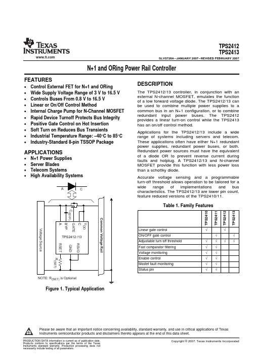
DEVICE TPS2412 TPS2413
ORDERING INFORMATION(1)
TEMPERATURE
PACKAGE (2)
ORDERING CODE
–40°C to 85°C
PW (TSSOP - 8)
TPS2412PW TPS2413PW
MARKING TPS2412 TPS2413
(1) Add an R suffix to the device type for tape and reel. (2) For the most current package and ordering information, see the Package Option Addendum at the end
Accurate voltage sensing and a programmable turn-off threshold allows operation to be tailored for a wide range of implementations and bus characteristics. The TPS2412/13 are lower pin count, feature reduced versions of the TPS2410/11.
VALUE –0.3 to 18
7.5 18 –0.3 to 30 –0.3 to 13 0.3 –0.3 to 7 Indefinite 2 500 Internally liited –65 to 150
UNIT V V V V V V V
kV V °C °C
(1) Stresses beyond those listed under absolute maximum ratings may cause permanent damage to the device. These are stress ratings only and functional operation of the device at these or any other conditions beyond those indicated under recommended operating conditions is not implied. Exposure to absolute-maximum-rated conditions for extended periods may affect device reliability.
JY2412 2 软启动功能 LED 线性 恒流驱动 IC规格说明文档

JY2412 2 软启动功能 LED 线性恒流驱动 IC概述JY2412 LED 恒流驱动 IC ,是 JY2410es 系列恒流驱动的升级版本,产品秉承了JY2410 的优良特性,更增加了多项最新的专利技术,使产品性能达到了一个新的高度。
JY2412 针对目前各种中小功率的 LED 照明产品而设计,适用于各种小功率球泡灯、日光灯、天花灯、吸顶灯、筒灯等产品。
JY2412 是在 JY2411 的基础上,增加一路恒流驱动模块而成。
具有 A /B 两路恒流驱动,其中,A 路采用内置 600v MOS 功率管,最大输出电流为80ma,B 路驱动输出采用外置 MOS 管,可以带动各种小功率 LED 负载,A/ B 两路输出可以分开使用,也可以合并使用以增加驱动器的输出电流, A/ B 两路驱动各自有电流检测端: csa 和csb ,使用时可以设定各自的电流,JY2412 具有体积小,外部线路结构简单,外围零件少的特点。
JY2412 具有极高的恒流精度,而且,工作时没有电磁辐射,可以轻松通过欧美的 EMI 检测。
JY2412 保持了 JY2410esxx系列产品优异的电气性能之外,产品嵌入了本公司最新的 LED软启动专利技术,LED 光源在上电时,其初始电流,仅为工作电流的 20%然后逐暂增加至 100%,实现了真正意义上的软启动。
产品特点JY2412 内部集成了两路高精度线性恒流模块、外部遥控器接口控制模块、外部PWM 及直流线性调光模块、温度控制模块等。
适合于高压非隔离LED 驱动方案,JY2412 具有两路恒流驱动模块,其中,模块 A 内部自带一枚 600V MOS 功率管,驱动电流达 80ma,B 模块恒流驱动采用 MOS管外挂方式,可以输出较大的电流。
相对JY2411,JY2412更适用于功率较大的 LED 灯具。
JY2412 的两路输出,可以单独使用任何一路,也可以两路同时使用。
可以单独驱动各自的负载,也可以合并使用以增加输出电流。
RP40-2412SGW中文资料

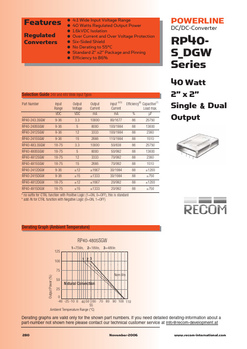
Derating graphs are valid only for the shown part numbers. If you need detailed derating-information about a part-number not shown here please contact our technical customer service at info@recom-development.at
280 November-2006
元器件交易网
POWERLINE
DC/DC-Converter
Derating Graph (Ambient Temperature)
RP40-S_DGW Series
RP40-4805SGW
RP40-243.3SGW RP40-2405SGW RP40-2412SGW RP40-2415SGW RP40-483.3SGW RP40-4805SGW RP40-4812SGW RP40-4815SGW RP40-2412DGW RP40-2415DGW RP40-4812DGW RP40-4815DGW
1=Natural Convection, 2=200LFM, 3=300LFM, 4=400LFM, 5=500LFM 1 2 3 45
125 100 75 Output Power (%) 50 25
Natural Convection
0 -40 -25 -10 0 40 50 60 70 80 90 100 110 55 Ambient Temperature Range (°C)
Without Heat-Sink With Heat-Sink
282
November-2006
HFBR-2412中文资料
Fiber-Optic Transmitter and ReceiverReliability Data IntroductionAgilent Technologies’ quality system includes an ongoing reliability monitor program to generate a data base from which this reliability data sheet is published.Transmitter Reliability The HFBR-0400 Series fiberoptic transmitters incorporate AlGaAs emitters and double lens optical systems. This design allows the HFBR-14XX transmitters to be driven at a relatively low current level for a specified amount of coupled power into the fiber. Because transmitter forward currents are proportional to failure rates, a low current translates into excellent transmitter reliability. To further improve reliability, Agilent has implemented a proprietary wafer screening technology that identifies dislocations whichcan lead to the formation of darkline defects (the primary mechanism for transmitter light output failures).HFBR-0400 SeriesTransmitters:HFBR-1402, -1412, -1404, -1414Receivers:HFBR-2402, -2412, -2406, -2416 Transmtter reliability data hasbeen calculated using 100 mAforward current and a 100% dutyfactor. In many actual useconditions, a 50% duty factor andlower forward currents are highlyprobable. When this is true,transmitter reliability will besubstantially better. The degree ofimprovement can be projected byexamining the footnotes below theHFBR-14XX data.Reliability PredictionModelThe reliability prediction modelused to project failure rate andmean time to failure (MTTF) atvarious temperatures shown in thesecond table assumes anexponential cumulative failurefunction (constant failure rate).The Arrhenius temperaturederating equation is used. AgilentTechnologies assumes no failuremechanism change between stressand use conditions. A conservativeactivation energy of 0.43 eV wasused and is derived from MIL-HDBD-217 for hybrid devices.Confidence intervals are basedupon the chi-squaredprediction method associated withexponential distributions.Fiber-Optic TransmitterReliability Data HFBR-1402HFBR-1412HFBR-1404HFBR-1414High Temperature Operating Life TestA. Demonstrated PerformanceTest Equivalent Test Condition Samples Device Hours Failures HTOL T A = 85°C, I F = 100 mA880 units879,5003B. Failure CriteriaFailure has occurred when the unitfails catastrophically, or when thelight output power decreases 3 dB.Point Typical PerformancePerformance [1]in Time [2]in Time(90% Confidence) Ambient Junction MTTF [1]FITs [3]MTTF [2]FITs [3] Temperature (°C)Temperature (°C)(hours)(/109 Hours)(hours)(/109 Hours) 85100293,0003411131,00075968095352,0002844158,00063347590424,0002360190,00052557085514,0001947231,00043376580626,0001598281,00035606075766,0001305344,00029055570945,0001059424,000235750651,172,000854526,000190145601,462,000684657,000152340551,838,000544825,000121235502,326,0004301,044,00095830452,965,0003371,331,00075125403,810,0002631,711,000585C. Failure Rate Prediction for Random Failures (I F @ 100 mA, 100% duty cycle)Notes:1. The point MTTF (representing an esti-mate of the mean point MTTF) is the total device hours divided by either the number performance that is expected from 90% ofall samples. This confidence interval isbased on the statistics of the distribution offailure rates prior to the onset of wear out.Refer to MIL-STD-690 for details of thismethodology.Fiber-Optic Link ReceiverReliability DataHFBR-2402HFBR-2412High Temperature Operating Life TestA. Demonstrated PerformanceTest Equivalent Test Condition Samples Device Hours Failures HTOL T A = 85°C, V CC = 5.25 V3,9602,370,0001B. Failure CriteriaFailure has occurred when the unitfails catastrophically. One devicefailed to switch logic states.Point Typical PerformancePerformance [1]in Time [2]in Time(90% Confidence) Ambient Junction MTTF [1]FITs [3]MTTF [2]FITs [3] Temperature (°C)Temperature (°C)(hours)(/109 Hours)(hours)(/109 Hours) 851002,370,000421609,0001,64080952,880,000346742,0001,34075903,530,000282909,0001,09070854,350,0002291,120,00089265805,400,0001841,390,00071960756,740,0001481,730,00057655708,480,0001172,180,000458506510,700,000932,750,000362456013,600,000733,510,000284405517,500,000564,520,000221355022,700,000435,850,000170304529,700,000337,650,000130254039,200,0002510,000,00099C. Failure Rate Prediction, Receiver (V CC = 5.25 V)Notes:1. The point MTTF (representing an esti-mate of the mean point MTTF) is the total device hours divided by either the number performance that is expected from 90% ofall samples. This confidence interval isuseful life failures. Refer to MIL-STD-690 fordetails of this methodology.Fiber-Optic Link ReceiverReliability DataHFBR-2406HFBR-2416High Temperature Operating Life TestA. Demonstrated PerformanceTest Equivalent Test Condition Samples Device Hours Failures HTOL T A = 85°C, V CC = 5.25 V2,2502,250,0000B. Failure CriteriaFailure has occurred when the unitfails catastrophically.Point Typical PerformancePerformance [1]in Time [2]in Time(90% Confidence) Ambient Junction MTTF [1]FITs [3]MTTF [2]FITs [3] Temperature (°C)Temperature (°C)(hours)(/109 Hours)(hours)(/109 Hours) 851002,250,000444977,164102380952,698,5163711,171,95385375903,252,6873071,412,62770870853,941,1732541,711,63358465804,801,4322082,085,24048060755,882,7441702,554,84939155707,250,3821383,148,80831850658,991,4071113,904,927256456011,222,799894,874,010205405514,102,949716,124,846163355017,848,023567,751,315129304522,755,516449,882,616101254029,238,4093412,698,10779C. Failure Rate Prediction, Receiver (V CC = 5.25 V)Notes:1. The point MTTF (representing an esti-mate of the mean point MTTF) is the total device hours divided by either the number performance that is expected from 90% ofall samples. This confidence interval isuseful life failures. Refer to MIL-STD-690 fordetails of this methodology.HFBR-0400 Mechanical and Environmental Test Data [1]MIL-STD-883D Units Total Test Name Reference Test Conditions Tested Failed Temperature Cycle1010500 cycles from -55 to +125°C, 15 minutes20201at extremes, 5 minutes transfer. [1]HFBR-1414500 cycles from -55 to +125°C, 15 minutes20900at extremes, 5 minutes transfer.[1]HFBR-2416 85/85T A = 85°C, 85% relative humidity,21407No bias, duration = 1,000 hours. [1]HFBR-1414T A = 85°C, 85% relative humidity,22206V CC = 5 volts, Duration = 1,000 hours[1]HFBR-2416 High Temperature1008T A = 125°C800 Storage Condition B1000 hoursResistance to2015Three 1 minute immersions.200 Solvents Brush after solvent immersion.Chemical Resistance— 5 minutes in Acetone, Methanol, Freon TF200and Boiling WaterVibration Variable 2007,20 G min., 20 to 2000 Hz.200 Frequency Condition B4, 4 minute cycles each X, Y, and Z.Thermal Shock1011-55°C to +125°C, 15 cycles600Condition B 5 min. dwell / 10 sec. transferMechanical Shock2002, 5 blows each X1, X2, Y1, Y2, Z1, Z2600Condition B1500 G, 0.5 msec. pulse.Port Wear Test [2]T A = 25°C500 connectorings200Less than 1 dBm variationConnector Side T A = 25°C 1 kg side load100 Load [3]Less than 1 dBm variationPort Strength [4]T A = 25°C 6 kg-cm (5.21 inch-lbs), no port damage100 Seal-Dye Penetrant101445 psi, 10 hours200 (Zyglo)Condition D No Leakage into microelectronic cavitySolderability2003245°C300 ESD Method 3015Human body model @ 10,000 V50HFBR-1414Human body model @ 2,000 V50HFBR-2402Human body model @ 1000 V50HFBR-2416Notes: See following page.Notes:1. Devices were preconditioned with 10 second, 260°C solder dip and 20 cycles, -40°C to 85°C, temperature cycle.2. Coupled power measurements were maximized before and after stress in determining the 1 dBm variation for SMA HFBR-0400 products. HFBR-0400 ST products do not require this due to the improved coupling design.3. The Connector Side Load test was only applied to HFBR-0400 SMA products. The Connector Side Load testing required that the housing be held so to prevent the leads from yielding. The load was applied through a SMA connectored fiber optic cable, perpendicular to the port. The product family is designed to limit cable and ferrule damage due to cable loading. The support and active leads should yield before damage to the cable or connector occurs. If extreme mechanical abuse of the cable/ connector is anticipated please contact Agilent’s Application Department for suggestions about mechanical strain relief. Due to the spring loaded feature of the ST connector, HFBR-0400 ST products will experience 1 dBm coupled power variation at a side load of less than 1 kg.4. The Port Strength test was designed to gauge the concerns with hand tightening the connector to the fiber optic port. The limit is set to alevel beyond most reasonable hand fastening loading.5. Package tests are defined as stresses that indicate the environmental strength of the package. Units tested indicate the total number of devices taken from the product family. While not all part numbers have been subjected to each stress, worst case products have been included.。
阿尔法电缆 2412C 型号 20AWG 双核电缆说明书

Alpha Wire | 711 Lidgerwood Avenue, Elizabeth, NJ 07207Tel: 1-800-52 ALPHA (25742), Web: Customer SpecificationPART NO. 2412CConstructionDiameters (In)1) Component 1 2 X 1 CONDa) Conductor20 (7/28) AWG TC0.038b) Insulation0.016" Wall, Nom. Polyethylene(PE)0.070(1) Color(s)Cond Color Cond Color Cond Color1BLACK2RED2) Cable Assembly 2 Components Cableda) Twists: 6.0 Twists/foot (min)3) Shield:Alum/Mylar Tape, 25% Overlap, Min.a) Foil Direction Foil Facing Outb) Drain Wire 20 (7/28) AWG TC4) Jacket 0.020" Wall, Nom.,PVC0.184 (0.194 Max.)a) Color(s) SLATEb) Print ALPHA WIRE-* P/N 2412C 2C 20 AWGSHIELDED 75C (UL) TYPE CMG OR AWM 2092 ----C(UL) CMG FT4 ROHS* = Factory Code[Note: Product may have c(UL) or CSA markings depending upon plant of manufacture.]Applicable Specifications1) UL AWM/STYLE 209260°C / 300 V RMSCMG75°CVW-12) CSA International C(UL) TYPE CMG75°CFT4Environmental1) EU Directive 2002/95/EC(RoHS):All materials used in the manufacture of this part are in compliance with EU Directive2002/95/EU regarding the restriction of use of certain hazardous substances in electrical andelectronic equipment. Consult Alpha Wire's web site for compliance Date of Manufacture.2) California Proposition 65:The outer surface materials used in the manufacture of this part meet the requirements of California Proposition 65.PropertiesPhysical & Mechanical Properties1) Temperature Range-20 to 75°C2) Bend Radius10X Cable Diameter3) Pull Tension26 Lbs, MaximumElectrical Properties(For Engineering purposes only)1) Voltage Rating300 V RMS2) Capacitance22.7 pf/ft @1 kHz, Nominal Conductor to Conductor3) Ground Capacitance41 pf/ft @1 kHz, Nominal4) Characteristic Impedance685) Inductance0.19 µH/ft, Nominal6) Conductor DCR10.2 /1000ft @20°C, Nominal7) OA Shield DCR8.2 /1000ft @20°C, NominalOtherPackaging Flange x Traverse x Barrel (inches)a) 1000 FT12 x 6 x 3.5 Continuous lengthb) BOX 1000FT9-1/2 EASY REEL: Continuous lengthc) BOX 500FT7-5/8 EASY REEL: Continuous lengthd) 500 FT12 x 4.5 x 3.5 Continuous lengthe) 100 FT 6.5 x 4 x 2.5 Continuous length[Spool dimensions may vary slightly]Alpha Wire | 711 Lidgerwood Avenue, Elizabeth, NJ 07207Tel: 1-800-52 ALPHA (25742)Although Alpha Wire (“Alpha”) makes every reasonable effort to ensure there accuracy at the time of publication, information and specifications described herein are subject to errors or omissions and to changes without notice, and the listing of such information and specifications does not ensure product availability.Alpha provides the information and specifications herein on an “AS IS” basis, with no representations or warranties, whether express, statutory or implied. In no event will Alpha be liable for any damages (including consequential, indirect, incidental, special, punitive, or exemplary) whatsoever, even if Alpha had been advised of the possibility of such damages, whether in an action under contract, negligence or any other theory, arising out of or in connection with the use, or inability to use, the information or specifications described herein.Alpha Wire | 711 Lidgerwood Avenue, Elizabeth, NJ 07207Tel: 1-800-52 ALPHA (25742), Web: RoHS CERTIFICATE OF COMPLIANCETo Whom It May Concern:Alpha Wire Part Number:2412C2412C , RoHS-Compliant Commencing With11/1/2004ProductionThis document certifies that the Alpha part numbers cited above are manufactured in accordancewith Directive 2002/95/EC of the EuropeanParliament and of the Council of 27 January 2003,better known as the RoHS Directives, with regards to restrictions of the use of certain hazardoussubstances used in the manufacture of electrical and electronic equipment. The reader is referredto these Directives for the specific definitions and extents of these Directives. No Exemptions arerequired for RoHS Compliance on this item.Substance Maximum Control ValueLead0.1% by weight (1000 ppm)Mercury0.1% by weight (1000 ppm)Cadmium0.01% by weight (100 ppm)Hexavalent Chromium0.1% by weight (1000 ppm)Polybrominated Biphenyls (PBB)0.1% by weight (1000 ppm)Polybrominated Diphenyl Ethers (PBDE)Including Deca-BDE0.1% by weight (1000 ppm)The information provided in this document and disclosure is correct to the best of Alpha Wire'sknowledge, information and belief at the date of its release. The information provided is designedonly as a general guide for the safe handling, storage, and any other operation of the productitself or the one that it will become part of. The intent of this document is not to be considered awarranty or quality specification. Regulatory information is for guidance purposes only. Productusers are responsible for determining the applicability of legislation and regulations based ontheir individual usage of the product.Authorized Signatory for the Alpha Wire Company:Dave Watson, Director of Engineering & QA10/31/2012。
- 1、下载文档前请自行甄别文档内容的完整性,平台不提供额外的编辑、内容补充、找答案等附加服务。
- 2、"仅部分预览"的文档,不可在线预览部分如存在完整性等问题,可反馈申请退款(可完整预览的文档不适用该条件!)。
- 3、如文档侵犯您的权益,请联系客服反馈,我们会尽快为您处理(人工客服工作时间:9:00-18:30)。
Deviation / Load
25.000 20.000
Deviation / Load
Deviation from Nominal (%)
15.000 10.000 5.000 0.000 -5.000 -10.000
Deviation from Nominal (%)
Deviation from Nominal (%)
100 80 60
RG-xx09D
Efficiency / Load
80 60 40
1215
0505
1205
0509
0515 Efficiency % 3.315
40 20 0
1209 3.309
Efficiency %
20 0
3.305
Efficiency %
100%
20 0
0%
20%
40%
60%
ECONOLINE
DC/DC-Converter
RJ & RG Series
1 Watt DIP14 Single & Dual Output
Input Voltage (VDC) 1.8, 3.3, 5, 9, 12, 15, 24 1.8, 3.3, 5, 9, 12, 15, 24 1.8, 3.3, 5, 9, 12, 15, 24 1.8, 3.3, 5, 9, 12, 15, 24 1.8, 3.3, 5, 9, 12, 15, 24 1.8, 3.3, 5, 9, 12, 15, 24 1.8, 3.3, 5, 9, 12, 15, 24 1.8, 3.3, 5, 9, 12, 15, 24 1.8, 3.3, 5, 9, 12, 15, 24 1.8, 3.3, 5, 9, 12, 15, 24 1.8, 3.3, 5, 9, 12, 15, 24 1.8, 3.3, 5, 9, 12, 15, 24 1.8, 3.3, 5, 9, 12, 15, 24 1.8, 3.3, 5, 9, 12, 15, 24
xx = Input Voltage * add Suffix “P” for Continuous Short Circuit Protection, e.g. RJ-0505S/P, RG-0505D/HP
EN-60950-1 Certified EN-60601-1 Certified
Specifications (Core Operating Area)
0% 20% 40% 60% Total Output current (%)
80%
100%
0% 20% 40% 60% Total Output current (%)
80%
100%
RJ-xx15S
Efficiency / Load
100 80 60 40 100
RG-xx05D
Efficiency / Load
Safe Operating Area
85 Operating Temperature °C
-40
0
50
100
150
July-2006
35
元器件交易网
ECONOLINE
DC/DC-Converter
Specifications (Core Operating Area)
25.000 20.000
Deviation / Load
Deviation from Nominal (%)
Deviation from Nominal (%)
15.000 10.000 5.000 0.000 -5.000 -10.000
15.000 10.000 5.000 0.000 -5.000 -10.000
元器件交易网
Features
Unregulated Converters
Selection Guide
Part Number DIP 14 RJ-xx1.8S RJ-xx3.3S RJ-xx05S RJ-xx09S RJ-xx12S RJ-xx15S RJ-xx24S RG-xx1.8D RG-xx3.3D RG-xx05D RG-xx09D RG-xx12D RG-xx15D RG-xx24D 4kV (H) (H) (H) (H) (H) (H) (H) (H) (H) (H) (H) (H) (H) (H)
80%
100%
0% 20% 40% 60% Total Output current (%)
80%
100%
0% 20% 40% 60% Total Output current (%)
80%
100%
36
July-2006
元器件交易网
● ● ● ● ● ●
Dual Output from a Single Input Rail 3kVDC & 4kVDC Isolation Optional Continuous Short Circuit Protected Custom Solutions Available UL94V-0 Package Material Efficiency to 84%
Deviation / Load
Deviation from Nominal (%)
Deviation from Nominal (%)
15.000 10.000 5.000 0.000 -5.000 -10.000
0512
1212
15.000 10.000 5.000 0.000 -5.000 -10.000
MTBF (+25°C) (+85°C)
RJ & RG Series
992 x 103 hours 1012 x 103 hours 145 x 103 hours 151 x 103 hours
}
Detailed Information see Application Notes chapter "MTBF"
40 20 0
1215
Efficiency %
20 0
0%
20%
40%
60%
80%
100%
0%
20%
40%
60%
80%
100%
Total Output current (%)
Total Output current (%)
Deviation / Load
25.000 20.000 25.000 20.000
Input Voltage Range Output Voltage Accuracy Line Voltage Regulation Load Voltage Regulation (10% to 100% full load) Output Ripple and Noise (20MHz limited) Operating Frequency Efficiency at Full Load No Load Power Consumption Isolation Voltage Rated Working Voltage Isolation Voltage Rated Working Voltage Isolation Capacitance Isolation Resistance Short Circuit Protection P-Suffix Operating Temperature Range (free air convection) Storage Temperature Range Relative Humidity Package Weight H-Suffix H-Suffix (tested for 1 second) (long term isolation) (tested for 1 second) (long term isolation) 1.8V, 3.3V output types 5V output type 9V, 12V, 15V, 24V output types ±10% ±5% 1.2%/1% of Vin typ. 20% max. 15% max. 10% max. 100mVp-p max. 57kHz min. / 90kHz typ. / 105kHz max. 70% min. / 80% typ. 102mW min./180mW typ./260mW max. 3000VDC min. see Application Notes. 4000VDC min. see Application Notes
Output Power (%)
100 80 60 40 30 20 0
Derating-Graph
(Ambient Temperature)
20pF min. / 65pF max. 15 GΩ min. 1 Second Continuous -40°C to +85°C (see Graph) -55°C to +125°C 95% RH 2.5g continued on next page
100 80 60 100
RJ-xx12S
Efficiency / Load
80 60
3.305
1205
0509
0512
1212
0505 Efficiency %
40 20 0
1209 Efficiency % 3.309
Efficiency %
40 20 0
3.312
20 0
0% 20% 40% 60% Total Output current (%)
ECONOLINE
DC/DC-Converter
Typical Characteristics