2011jamc2675_bai
RAL-GZ041-2011 Candles
CandlesQuality Assurance RAL-GZ 041Edition November 20112ContentsPage General Quality and Inspection Specificationsfor candles - RAL-GZ 0411Range of application (4)2Principle (4)3Concomitant regulations, guidelines and standards (4)4Terms and definitions (4)5Quality and inspection specifications (4)6Monitoring (5)7Labelling (6)8Amendments (6)RAL-GZ 041/1 Special Quality and Inspection Specificationsfor household candles, tapered candles, pillar candles, lights (indoor use) and other candles1-1Range of application (7)1-2Quality specifications (7)1-3Test specifications (7)1-4General assessment (9)1-5Monitoring (9)1-6Labelling (10)1-7Amendments (10)RAL-GZ 041/2 Special Quality and Inspection Specifications for tea lights2-1Range of application (11)2-2Quality specifications (11)2-3Test specifications (11)2-4General assessment (13)2-5Monitoring (13)2-6Labelling (13)2-7Amendments (13)RAL-GZ 041/3 Special Quality and Inspection Specifications for grave yard lights3-1Range of application (14)3-2Quality specifications (14)3-3Test specifications (14)3-4General assessment (14)3-5Monitoring (14)3-6Labelling (15)3-7Amendments (15)Requirements for the selection of raw materials and additives (16)Regulations for the award and use of the candle quality mark1Quality basis (20)2Award (20)3Use (20)4Monitoring (20)5Penalties for contravention (20)6Complaint (21)7Reinstatement (21)8Amendments (21)Pattern 1Notice of Obligation (22)Pattern 2Awarding Certificate (23)3General Quality and Inspection Specifications for candles - RAL-GZ 0411 Range of applicationThe Special Quality and Inspection Specifications es-tablish content and scope of monitoring measures as well as comments on the marking of graded candles. Reproducible quality criteria for the candle product areas (household candles, tapered candles, pillar can-dles, and others), tea lights and grave yard lights are established in the framework of Special Quality and Inspection Specifications.2 PrincipleCandles with the quality label must meet the require-ments of preventive health protection and environ-mental protection.Annex 1 applies in particular. It is being continuously supplemented in compliance with the state of the art.3 Concomitant regulations,Guidelines and standardsQuality assurance requires compliance with the follow-ing guidelines. Relevant are the sections relating to the range of application of the General and Special Quality and Inspection Specifications.- Candles, Quality and Marking Specifications RAL 040 A 2,- Oil Lights, Quality and Marking Specifications RAL 040 B 2,- EN 15426 Candles – Specification for sooting behav-iour,- DGF standard methods,- EN 71, Safety of Toys, Part 3: Migration of specific elements,- IFRA Process Guidelines.4 Terms and definitions4.1 Candles (partial extract from RAL 040 A 2) 4.1.1 Paraffin candlesThe burning mass consists of paraffin.4.1.2 StearincandlesThe burning mass consists of a minimum of 90 % by weight of stearin. In this case, it is permissible to pro-vide the candle body with a coat that does not consist of stearin. This dip coat must not have a weight of more than 10 % wt. 4.1.3 BeeswaxcandlesThe exclusive term beeswax candle is only permissibleif the burning mass of the candle consists only of bees-wax without any additive.If a scent and/or a dye is added to the beeswax, the term "beeswax candle" has to be accom-panied by an explicit reference to this additive.4.1.4 CompositioncandlesThe burning mass of a composition candle consists of amixture of different waxes. The addition of a specificwax may be indicated.If the burning mass contains beeswax, e.g. 10 % byweight, or if the candle is only coated with beeswax, thisbeeswax part and/or the beeswax coating can be indi-cated.The way of indication must not pretend a bigger bees-wax part than the candle actually contains however. It isnot allowed to use the indication beeswax in a way thatimplies the impression that the candle is a beeswaxcandle in accordance with section 4.1.3.4.2 Self-extinguishing candlesThe wick of self-extinguishing, self-going-out and self-fading candles must not reach the bottom of the candlewhen it is still burning.4.3 Oil lights (extract from RAL 040 B 2)Oil lightsOil lights consist of a solid burning mass and a wick thatare surrounded by an inflexible container.The term "oil light" may only be used if the burningmass exclusively consists of hardened vegetable oils orsolid vegetable fats.For "composition oil lights" not only solid, hardened or unhardened vegetable oils or fats may be used, but alsosuch of animal origin.They are mixed with waxes, solid fatty acids or solid hydrocarbon compounds.The share of the solid, hardened or unhardened vege-table or animal oils and fats in composition oil lights hasto be indicated in percent and must not be below 30 %.5 Quality and inspectionspecificationsThe binding compliance with the Quality and Inspection Specifications is the compulsory prerequisite for the preparation for and carrying out of the initial inspection.4The sections of the concomitant regulations related to the range of application of the General and Special Quality and Inspection Specifications are relevant here.6 MonitoringGeneral notesThe monitoring is subdivided into:- Initial inspection,- Self-monitoring,- External monitoring,- Repeat inspection.6.1 Initial inspectionPassing the initial inspection is the prerequisite for be-ing awarded and permitted to use the quality mark "Candles". The initial inspection focuses on whether the applicant’s products completely meet the General and the respective Special Quality and Inspection Specifica-tions. The applicant is required to prove - by submission of a manufacturer's certificate issued by the applicant’s suppliers - that the "Requirements for the Selection of Raw Materials and Additives" according to Appendix 1 of the Quality and Inspection Specifications are fulfilled. The initial inspection is initiated by the Quality Commit-tee of the Quality Association; an independent and accredited testing organization or an attested neutral expert is assigned to perform the inspection. Furthermore, the initial inspection is dedicated to show whether the prerequisites for a proper compliance with the General and the respective Special Quality and Inspection Specifications are given. The manufacturer is required to allow the external inspector, upon request, to inspect the records on previous tests (e.g. test proto-cols) at the initial inspection.The external inspector issues an inspection report cov-ering the initial inspection. One copy of the inspection report is sent to the applicant and another one to the Quality Committee of the Quality Association.The assigned inspector must use forms prepared by the Quality Association for the initial inspection.6.2 SeIf-monitoringAll users of the quality mark must perform a continuous and verifiable self-monitoring of all graded products in terms of their compliance with the General and the respective Special Quality and Inspection Specifica-tions.Carefully kept records (daily reports) must be main-tained on self-monitoring. These records are to be re-tained for two years in a suitable form and must be provided at the external inspection. When carrying out self-monitoring, the quality mark user has got to use inspection reports specified by the Quality Association. 6.3 External monitoringThe external monitoring is dedicated to show whether the General and the respective Special Quality and Inspection Specifications as well as the fixed require-ments for the orderly performance of the inspections are still met by the quality mark user. External monitoring must be carried out at least once a year without prior notice by an external inspector appointed by the Quality Committee of the Quality Association and at the factory of the quality mark user. It has to be based on the in-spection forms specified and provided by the Quality Association. Only products that are not labelled with the quality mark are excluded from the inspection. The assigned external inspector must identify himself on site by presenting a written order issued by the Quality Committee of the Quality Association. The obligation to legitimate must not delay the performance of the in-spection.In the framework of external monitoring, the inspector has got to check the handling of the internal self-monitoring and evaluate its results regarding complete-ness and conclusiveness. Furthermore, the quality mark user has got to prove that the Requirements for the Selection of Raw Materials and Additives according to Appendix 1 of the present Quality and Inspection Speci-fications are still met by submitting manufacturers' cer-tificates issued by their suppliers.6.4 Repeat inspectionIf the assigned external inspector detects short-comings in the quality mark user´s quality assurance (according to the General and the respective Special Quality and Inspection Specifications) in the framework of the exter-nal inspection, these have to be reported to the Quality Committee of the Quality Association immediately, notwithstanding the preparation of an appropriate in-spection report.In response, the Board of the Quality Association may order a repeat inspection in consultation with the Quality Committee, whereupon the Quality Committee of the Quality Association settles date, content and scope of this inspection.If the repeat inspection is not passed either, further measures according to Section 5 of the implementation requirements may be taken by the Board of the Quality Association in consultation with the Quality Committee.6.5 Inspection costsThe costs of all monitoring or inspections carried out have to be borne by the applicant or quality mark user. 6.6 Inspection and monitoring reportsAn inspection report has to be prepared on any inspec-tion or monitoring carried out by the assigned external inspector. One copy of the inspection report must be sent to the applicant or quality mark user as well as to the Quality Committee of the Quality Association.57 LabellingProducts manufactured in accordance with the General and the respective Special Quality and Inspection Specifications and for which the quality mark of the Quality Association has been awarded may be labelled using one of the following quality marks: The quality mark is only allowed to be used in a way that the producer can either be identified by- his name or- an identification number that is given and exclusively deposited by the Quality Association or- the EAN-Code.For the awarding and the use of the quality mark only the implementation rules of the Quality Association for Candles are applicable.8 AmendmentsAmendments to the General and Special Quality and Inspection Specifications, even of editorial nature, re-quire the prior written approval by RAL to become effec-tive. They are implemented by the Board of the Quality Association notifying the quality mark users and giving an adequate transition period.6Special Quality and Inspection Specificationsfor household candles, tapered candles, pillar candles, lights for indoor use and other candlesRAL-GZ 041/11-1 Range of applicationThe present Special Quality and Inspection Specifica-tions apply to the production of candles with a smooth surface for product varieties such as Advent candles, altar candles, Christmas tree candles, anniversary can-dles, household candles, offering candles, pyramid can-dles, cake lights, tapered candles, cylindrical candles, pillar candles. They may also be applied to models with ornamental surfaces and lights in containers made of any adequate material provided that they do not refer to product varieties covered by the Special Quality and Inspection Specifications for tea lights and grave yard lights.1-1.1 General notesThese Special Quality and Inspection Specifications only apply in combination with the General Quality and In-spection Specifications.1-2 Quality specifications1-2.1 Optical and technical requirements1-2.1.1 AppearanceThe wick has got to be positioned in the centre. Excep-tion: Candles with more than one wick.When viewed with the naked eye and without technical aids, the candle surface has got to be free of bubbles, cracks, chips and damage. Exceptions are only admissi-ble if these features are an integral part of the decora-tion.The candle needs to have the required colour shade and intensity and has to meet any candle dimensions shown on the packaging (see section 1-3.7).1-2.1.2 Burning behaviourAfter being lit, the candle has to show a bright, calm flame and gradually form a cup rim surrounding the so-called burning bowl.Furthermore, it must be ensured that the wick has a medium curvature while the candle is burning (see sec-tion 1-3.4) so that the flame burns without visible release of soot and does not drip (see section 1-3.5).For technical reasons, the evaluation of the burning behaviour regarding the compliance with these require-ments is only possible down to a residual height of 30 mm for pillar candles with a diameter between 31 and 60 mm, a residual height of 40 mm for pillar candles with a diameter of more than 60 mm and a residual height of 80 mm for altar candles respectively. After the flame has been extinguished, the tip of the wick continues to glow for some time by its very nature. This is associated with releasing a trail of smoke. For candles with a diameter of 30 mm or less, this process should be terminated within a period of 15 seconds. For candles with a diameter of more than 30 mm, the flat wick is only allowed to glow up to 20 seconds after the extinction of the flame; however – and in this case this is also binding for round wicks – the wick is not allowed to burn down completely so that the wick can still be relit without any problems and the candle continues to burn properly.If a burning time is stated on the packaging, it has got to be met (see section 1-3.7).1-2.2 Additional requirements for lightsThe burning mass of lights is located within a solid con-tainer. The container must neither be deformed nor de-stroyed nor ignited by the flame. The dripping test ac-cording to section 1-3.5 does not apply. Self-extinction at the end of the whole burning period must not occur until only a slight remainder of the burning mass is left in the container.1-3Test specifications1-3.1 SamplingThe tests are performed with finished candles that are ready for marketing.The samples shall be taken from the current production.The number of samples, depending on the production output, is agreed upon with the external inspection insti-tute.Length and diameter of the samples are measured ac-cording to RAL 040 A 2, section D 3, and recorded in mm as follows: The distance is regarded as a measure of the length between candle foot and wick outlet at the candle top. The diameter is measured as the maximum diameter at the candle foot.1-3.2 Spatial conditions and distances for burning testsFor the burning tests, the testing room temperature has got to range between 20 0C and 25 0C. The candles have to be placed upright - protected from draught as far as possible – and spaced adequately from each other de-pending on the candle format so that the candles do not influence each other by emitting heat.1-3.3 Burning cyclesThe sample candles are to be burned in different burning cycles depending on the candle size.78Burning Cycle 1 for Christmas tree candles, cake lights, egg shaped candles and other candle types with a maximum weight of 40 g:Cycle 1Continuous burning to a residual height of approx. 20 mm above the candle footBurning Cycle 2 and 3 for candles with a weight above 40 g and a maximum diameter of 30 mm:Cycle 2Continuous burning to a residual height of approx. 20 mm above the candle footCycle 3Burning for 2 hours, at least 1 hour pause, burning for 2 hoursBurning Cycle 4 and 5 for candles with a diameter of 31 to 60 mm (alternating from day to day):Cycle 4Burning for 4 hoursCycle 5Burning for 4 hours, at least 1 hour pause, burning for 4 hoursBurning Cycle 6 for candles with a diameter above 60 mm:Cycle 6Burning for 4 hours, at least 1 hour pauseBurning for 4 hours, at least 1 hour pauseBurning for 4 hours, at least 1 hour pauseBurning for 4 hoursBurning Cycle 7 for lights:Cycle 7Burning for 4 hours, at least 1 hour pause, repetition until self-extinctionBurning Cycle for maxi lights:Cycle 8Burning for 4 hours, at least 1 hour pause, afterwards continuous burning until self-extinctionNote:A maxi light is a special type of light with a cylindrical wax body and a typical diameter of 55 to 60 mm and a typical height of 20 to 30 mm. On the market, maxi lights might also be found with names like jumbo light, medi light, deco light etc.The candle burning shall be done on a heat resistant, non-flammable surface. The thermal conductivity of this surface should be as low as possible in order to minimize its influence on the burning behaviour of the candles,especially on lights. For this reason, burning candles directly on surfaces like metal or tiles is not suitable.1-3.4 Wick postureThe wick protrudes straight out of the candle and is sup-posed to bend evenly up to the outer edge of the flame when burning, where the flame temperature is the high-est, so that the complete, gradual burning of the wick tip takes place there.Consequently, a slight wick curvature according to Fig. 1 is ideal.The wick posture while burning is assessed visually.AssessmentWick shows curvature according to Fig. 1Wick posture goodWick curvature deviates sig-nificantly from Fig. 1Wick posture poor1-3.5 Dripping resistanceDripping is to be understood as burning mass running out of the burning bowl of the candle. The candle is drip-fast when this is prevented by the cup rim.In case of candles with a maximum diameter of 30 mm, slight wax run-off is tolerable if the following applies:When re-lighting the candle, the wick can only reach its full suction and capillary effect after a few minutes. Con-sequently, this phase may temporarily involve several drops of wax running off. This phenomenon should not be evaluated as insufficient dripping resistance.The assessment of the dripping resistance is performed visually.AssessmentCup rim prevents run-off Dripping resistancegoodMolten burning mass runs down the candle Dripping resistance poor1-3.6 Sooting behaviour / afterglowBurning with no release of soot at all is not possible for physicochemical reasons, especially in the lighting phase and directly after the flame has expired. The soot release has to be minimized however, especially by optimally balancing candle material and wick so that the candle emits only very small amounts of soot.Assessment of the sooting behaviour based on two criteriaa) visualNo visible release of soot Sooting behaviourgoodCandle sooting visibly Sooting behaviourpoorb) based on the testing procedure according to EN15426:2007 section 8For candles, except ball candles, egg candles, special shaped candles and candles with a diameter of more than 70 mm, the sooting behaviour has to be additionally assessed according to the following criteria:- An hourly soot index of max. 1.0 has to be met (visi-ble sooting can be expected at an hourly soot index of approx. 1.2 or more).The candle has to fulfil both criteria.Assessment of the afterglow for candles with a maximum diameter of 30 mmAfterglow terminated within15 secondsgoodAfterglow exceeds 15 sec-ondspoorAssessment of the afterglow for flat wick candles with a diameter above 30 mm diameterAfterglow terminated within20 secondsgoodAfterglow exceeds 20 sec-onds poor1-3.7 Compliance with dimensions andburningtimeThese characteristics are only relevant if expresslystated in the marketing of the candle type.Assessmenta) DimensionsDimensions adhered to goodDimensions not adhered to poorA maximum minus tolerance of 2 % but at least 1 mm isadmissible for diameter and length.b) Burning timeThe burning time is defined as the sum of all burningperiods from the first ignition until self-extinction.Burning time achieved goodBurning time not achieved poorWhen declaring a burning time like “approx.” or “ “, amaximum minus tolerance of 10 % is admissible.1-3.8 Burning mass remainder of lightsAfter self-extinction at the end of the entire burning, theburning mass remainder of lights with a cylindrical shapeand a maximum inner diameter of 70 mm is allowed tocome to a maximum of 2 g or 12 % of the initial burningmass.1-4 General assessmentThe general assessment of the candle is made on basisof the inspection reports on self-monitoring and externalmonitoring (assessment sheets) specified by the QualityAssociation.1-5 Monitoring1-5.1 Basic principlesThe basic principles for testing graded candles are sub-ject to the General Quality and Inspection Specifications.1-5.2 Initial inspectionScope and procedure result from section 6.1 of the Gen-eral Quality and Inspection Specifications in combinationwith the requirements given in sections 1-2 and 1-3 ofthe Special Quality and Inspection Specifications.91-5.3 Self-monitoringContent and scope of self-monitoring by the quality mark users result from section 6.2 of the General Quality and Inspection Specifications in combination with the re-quirements given in sections 1-2 and 1-3 of the Special Quality and Inspection Specifications.1-5.4 External monitoringScope and procedure result from section 6.3 of the Gen-eral Quality and Inspection Specifications in combination with sections 1-2 and 1-3 of the Special Quality and Inspection Specifications.1-5.5 Repeat inspectionProcedures of the repeat inspection are subject to sec-tion 6.4 of the General Quality and Inspection Specifica-tions. 1-6 LabellingThe labelling of graded candles is subject to section 7 of the General Quality and Inspection Specifications. Can-dles that have been awarded with the quality mark of the Quality Association may be labelled using one of the following quality marks shown below:1-7 AmendmentsAmendments to the Special Quality and Inspection Specifications are subject to section 8 of the General Quality and Inspection Specifications.10Special Quality and Inspection Specificationsfor tea lightsRAL-GZ 041/22-1 Range of applicationThe present Special Quality and Inspection Specifica-tions apply to the production of tea lights. Tea lights are candles that are burned in a non-combustible container made of metal, glass or plastics for example. The con-tainer prevents the burning mass from running off. Tea lights are accordingly termed when marketed and dedi-cated to be burned in warming stands to keep tea, cof-fee or other liquids contained in a pot positioned on the warming stand hot.Consumers increasingly use tea lights for illumination, comparable to the customary use of candles.2-1.1 General notesThe present Special Quality and Inspection Specifica-tions are only applicable in combination with the Gen-eral Quality and Inspection Specifications.2-2 Quality specifications2-2.1 Optical and technical requirements2-2.1.1 Appearance / wick positionWhen viewed with the naked eye and without technical aids, the wax surface has got to be free of impurities. The wick has got to be positioned in the centre.2-2.1.2 Dimensions /weight / burning time Standard tea lights have got the following dimensions (wax body without container, wick holder or wick):Height max. 17 mmDiameter 36-39 mmWeight min. 12 gThey have to fulfil a minimum burning time of 4 hours. Larger dimensions and a wick that is too thick may cause an oversized flame. The dimensions of the warm-ing stand might be insufficient for it and this could pos-sibly result in adverse effects (see section 2-3.2, first hyphen).2-2.1.3 Burning behaviourAfter being lit, the tea light has to show a bright calm flame and burn evenly.The flame height has to be at least 14 mm after the initial burning phase until shortly before the flame extin-guishes on its own. The flame must burn without visible release of soot.Once the flame has been extinguished, the tip of the wick continues to glow for some time by its very nature. This is associated with releasing a trail of smoke. This process has to be terminated within 10 seconds.Self-extinction at the end of the whole burning period must not occur until only a slight wax remainder is left in the container (see section 2-3.10).2-3 Test specifications2-3.1 General notesTo begin with, basic one-off tests are to be carried out per production series as described hereafter in sections 2-3.2 and 2-3.3. Provided that these two basic tests show positive results, the tea lights may be subjected to the routine inspections according to sections 2-3.4 to 2-3.10.2-3.2 One-off warming capacity testThe warming capacity is tested only once for each tea light series as long as the series remain unchanged in design, material specifications and manufacturing proc-ess. Warming capacity means that the tea light burning in the warming stand is able to keep the hot beverage placed on it at a temperature of at least 55 ºC due to the heat emission of the flame.- Design features of an appropriate warming stand:The distance from tea light (top edge) to the top plate of the stand and thus the bottom of the pot intended to be kept warm, has got to be at least 40mm. A shorter distance may result in soot depos-its, heat accumulation, creation of a larger flame and damaging the warming stand or warming ves-sel (cracking).Sufficient supply of fresh air has got to be guaran-teed. This is why the side walls of the warming stand need to have openings (ventilation holes).For the reason of heat circulation, a symmetric ar-rangement of at least three ventilation holes is re-quired. Their size should be at least 9 cm2 in total.The ventilation holes shall be arranged below the top edge of the tea light.To prevent heat accumulation, facilities for heat re-lease must be arranged between top plate and side wall of the warming stand, for instance a ven-tilation gap of 3 mm or holes in the top plate or inrim.The material the warming stand is made of is not allowed to be combustible and has got to with-11stand a temperature stress of up to 110 0C at cer-tain points without deformation.- Test Procedure:The warming capacity is tested while burning thetea light without any interruption (continuous burn-ing). The tea light is lit in the stand. A beaker - e.g.a 1 litre laboratory beaker (for example SchottDuran 1000 ml, flat form, article-no. 211065408) -filled with 1 litre of water is placed on the stand af-ter the tea light has burned for 5 minutes. The wa-ter must already have a temperature between 800C and 90 0C. The beaker is covered with a glasslid allowing the formed condensation to drip back.The water temperature is measured at least aftereach hour. When measuring, the thermometer isnot allowed to either touch the wall or the bottomof the beaker (3 cm distance).- Assessment:The warming capacity of the tea light is sufficient ifall measurements are at least 55 0C.2-3.3 One-off burning test in the warming standThe burning test in the warming stand is required only once for each tea light series as long as the series remain unchanged in design, material specifications and manufacturing process.Burning Cycle: Burning for 60 minutes, at least 1hour pause, repetition until self-extinctionThe objectives of the burning test in the warming stand are to achieve a flame height of at least 14 mm, to achieve a burning time of at least 4 hours and to mini-mize the wax remainder.Assessment: Flame height:according to section 2.3.7Burningtime:according to section 2-3.8Waxremainderaccording to section 2-3.10This basic test is only passed if all assessments are positive.2-3.4 Sampling for routine testsThe number of samples depends on the production output and has to be agreed upon with the external inspection institute.Height and diameter as well as the weight of the sample - without container, wick-holder and wick - are meas-ured and recorded in mm or g respectively.2-3.5 Spatial conditionsFor the burning test, the testing room temperature has got to range between 20 ºC and 25 0C.The room shall be extensively protected from draught.2-3.6 Burning cycle for routine testingThe routine testing of the burning properties (flame height, sooting behaviour, burning time, wax remainder) of the tea lights is performed according to the following burning cycle:Continuous burning until self-extinction without using a warming stand.The tea lights shall be burned on a heat resistant, non-flammable surface. The thermal conductivity of this surface should be as low as possible in order to mini-mize its influence on the burning behaviour. For this reason, burning tea lights directly on surfaces like metal or tiles is not suitable.2-3.7 Flame heightIn case of a non-optimal adjustment of burning mass and wick, the flame might be too small. During the initial burning phase (until the surface of the wax body is completely liquefied) and near the self-extinction of the flame (5 minutes before the extinction) height variations might occur however. During the remaining period, the flame height has got to be at least 14 mm, measured from the surface of the liquid burning mass to the tip of the flame.AssessmentFlame height always at least 14mmEvaluation: goodFlame height partly below 14mmEvaluation: poor2-3.8 Burning timeAssessmentThe burning time is at least4 hoursEvaluation: goodThe burning time is shorter Evaluation: poor2-3.9 Sooting behaviour / afterglowBurning with no release of soot at all is not possible for physicochemical reasons, especially in the lighting phase and directly after the flame has expired. The soot release has got to be minimized however, especially by optimally balancing candle material and wick so that the tea light emits only very small amounts of soot.12。
SIG SAUER 556xi
2. Pull the rear takedown pin from left to right until stopped by the detent. 7
2
W ADDITIONAL WARNING Early 556xi rifles chambered in 5.56x45mm NATO were fitted with a lighter hammer spring. Using that lower receiver assembly with this kit upgrade in 7.62x39mm, may produce light primer strikes and failures to fire. A hammer spring P/N 1511193 is available for factory installation in your lower to resolve this. Please contact SIG SAUER for further information.
3
TABLE OF CONTENTS
Warnings. . . . . . . . . . . . . . . . . . . . . . . . . . . . . . . . . . . . . . . . . . . . . . . . . . . . . . . . . . . . . 2 General Safety Information. . . . . . . . . . . . . . . . . . . . . . . . . . . . . . . . . . . . . . . . . . . . . . . 3 Caliber Exchange Kit Components. . . . . . . . . . . . . . . . . . . . . . . . . . . . . . . . . . . . . . . . . 5 Conversion Kit Components. . . . . . . . . . . . . . . . . . . . . . . . . . . . . . . . . . . . . . . . . . . . . . 5 Required Tools . . . . . . . . . . . . . . . . . . . . . . . . . . . . . . . . . . . . . . . . . . . . . . . . . . . . . . . 5 1.0 Preparing the 556xi for Installation of the Kit. . . . . . . . . . . . . . . . . . . . . . . . . . . . . . 6 2.0 Barrel Removal. . . . . . . . . . . . . . . . . . . . . . . . . . . . . . . . . . . . . . . . . . . . . . . . . . . . 13 3.0 Barrel Installation . . . . . . . . . . . . . . . . . . . . . . . . . . . . . . . . . . . . . . . . . . . . . . . . . . 16 4.0 Reassembly. . . . . . . . . . . . . . . . . . . . . . . . . . . . . . .. . . . . . 21 5.0 Conduct a Function Check. . . . . . . . . . . . . . . . . . . . . . . . . . . . . . . . . . . . . . . . . . . 28 6.0 Conversion Kit Instructions. . . . . . . . . . . . . . . . . . . . . . . . . . . . . . . . . . . . . . . . . . . 30
BPS4000 配置器规范说明书

1160-006AM040322BHTI Alternate Materials List2299-947-100-690115BHTI Procurement Specification for Epoxy Adhesive, Heat Resistant3299-947-320-820507BHTI Adhesive Film and Primer System, Intermediate Cure Temperature (260-290º F) Service Temperature 67-225º F)468A900000G011101BAC Finish Spec: F-15574A900000E990308BAC Finish Specification for F18 Aircraft674A900004DG M051220BAC Ctrl: Fract Crit Parts, F-18774A901001F981208BAC Std Finish Codes: F-18 A\C8901-947-002CA D950510BHTI Finish Specification for the V-22 Aircraft (Bell Boeing) Model 901) EMDAircraft9A-A-208See Special Notes DL C120719FED Ink, Marking, Stencil, Opaque10A-A-2962Cancelled - no s/s spec A980810Cancel Notice2FED Commercial Item Description Enamel, Alkyd, Exterior, Solvent Based, Low VocOk to use cancspec.11A-A-3097DC-970506Notice 4FED Commercial Item Description Adhesives, Cyanoacrylate, Rapid RoomTemperature-Curing, Solventless12A-A-3165DE A071116FED Lacquer, Gloss, for A/C Use13A-A-00208See Special Notes DL D121001FED Commercial Item Description Ink, Marking, Stencil, Opaque (Porous andNon-Porous Surfaces)14A-A-52080B980523Notice 1FED Tape, Lacing, and Tying, Nylon15A-A-52081DF B980523Notice 1FED Tape, Lacing, and Tying, Polyester16A-A-52082DC D090817FED Tape, Lacing and Tying, TFE-Fluorocarbon17A-A-52083BJ C040223FED Tape, Lacing, and Tying, Glass18A-A-52084B980523Notice 1FED Tape, Lacing and Tying, Aramid19A-A-55829DC A110322DLA Acetic Acid, Glacial, Technical20A-A-56032CN D030521Notice 1FED Commercial Item Description (CIDS) Ink, Marking, Epoxy Base21A-A-59126-970926FED Terminals, Feedthru (Insulated) and Terminals, Stud (Insulated andNoninsulated)22A-A-59132CR A100607ValidationNotice 1DLA Amyl Acetate, Technical23A-A-59135CR-971028FED Commercial Item Description Packaging Material, Sheet24A-A-59136CR-971028FED Cushioning Material, Packaging, Closed Cell Foam Plank25A-A-59178DD A041012Notice 1USGOVT Nipple, Electrical Terminal26A-A-59503DC C110303FED Commercial Item Description Nitrogen, Technical27A-A-59551CP A091022USGOVT Wire, Electrical, Copper (Uninsulated)28A-A-59569DJ C090122Notice 1DLA Qualification Sampling and Testing of Steels for Transverse TensileProperties29A-A-59588DJ B120130Notice 1FED Commercial Item Description Rubber, Silicone30A-A-59877CT-100909FED Commercial Item Description Insulating Compound, Electrical, Embedding31AIR4127CG - 071101SAE Steel: Chemical Composition and Hardenability32AISI-1010Unavailable-AISI Low Carb Stl Unavailable 33AISI-50100Unavailable-AISI Bearing Stl Unavailable 34AISI-52100Unavailable-AISI Bearing Stl Unavailable 35AISI-B-1112Unavailable-AISI Low Carb Free Mach Stl Unavailable 36AISI-C-1212Unavailable-AISI Material Spec, Stl Unavailable 37AISI-C-1213Unavailable-AISI Low Carb Free Mach Stl Unavailable 38AISI-C-1214Unavailable-AISI Material Spec, Stl Unavailable 39AMS 2175CR A100601SAE Castings, Classification and Inspection of40AMS 2201Cancelled CN Can940901SAE Tolerances Aluminum and Aluminum Alloy Bar, Rod, Wire, and ForgingStock Rolled or Cold-FinishedANSI H35.2 41AMS 2221G060201SAE Tolerances, Copper and Copper Alloy Bars and Rods42AMS 2222BG J060201SAE Tolerances, Copper and Copper Alloy Sheet, Strip, and Plate43AMS 2223BF H060201SAE Tolerances Copper and Copper Alloy Seamless Tubing44AMS 2224G060201SAE Tolerances Copper and Copper Alloy Wire45AMS 2241CN R070701SAE Tolerances, Corrosion and Heat-Resistant Steel, Iron Alloy, Titanium, andTitanium Alloy Bars and Wire46AMS 2242CC G080604SAE Tolerances Corrosion and Heat Resistant Steel, Iron Alloy, Titanium andTitanium Alloy Sheet, Strip and Plate47AMS 2243DH K130601SAE Tolerances Corrosion and Heat-Resistant Steel Tubing48AMS 2248DB G110301SAE Chemical Check Analysis Limits Corrosion and Heat-Resistant Steels andAlloys, Maraging and other Highly-Alloyed Steels, and Iron Alloys49AMS 2249CN G090701SAE Chemical Check Analysis Limits Titanium and Titanium Alloys50AMS 2259CN E071201SAE Chemical Check Analysis Limits Wrought Low-Alloy and Carbon Steels51AMS 2269CN F060501SAE Chemical Check Analysis Limits Nickel, Nickel Alloys, and Cobalt Alloys52AMS 2300CU L100801SAE Steel Cleanliness, Premium Aircraft-Quality Magnetic Particle InspectionProcedure53AMS 2301CT K100801SAE Steel Cleanliness, Aircraft Quality Magnetic Particle Inspection Procedure54AMS 2303CT F100801SAE Steel Cleanliness, Aircraft Quality, Martensitic Corrosion Resistant SteelsMagnetic Particle Inspection Procedure55AMS 2304CV B100801SAE Steel Cleanliness, Special Aircraft-Quality Magnetic Particle InspectionProcedure56AMS 2310BE F060201SAE Qualification Sampling and Testing of Steels for Transverse TensileProperties57AMS 2315DF G130201SAE Determination of Delta Ferrite Content58AMS 2350Cancelled - no s/s spec CN BA891001SAE Standards and Test Methods Ok to use cancspec.59AMS 2355DB K110301SAE Quality Assurance Sampling and Testing Aluminum Alloys and MagnesiumAlloy Wrought Products (Except Forging Stock), and Rolled, Forged, orFlash Welding Rings60AMS 2360CN D070701SAE Room Temperature Tensile Properties of Castings61AMS 2370DB K110601SAE Quality Assurance Sampling and Testing Carbon and Low-Alloy SteelWrought Products and Forging Stock62AMS 2371DB J110601SAE Quality Assurance Sampling and Testing Corrosion and Heat-ResistantSteels and Alloys Wrought Products and Forging Stock63APPROVED PER LR242820AMS 2372DP G140601SAE Quality Assurance Sampling and Testing Carbon and Low-Alloy SteelForgings64AMS 2375CN D070601SAE Control of Forgings Requiring First Article Approval65AMS 2380CN F080601SAE Approval and Control of Premium-Quality Titanium Alloys66AMS 2400DG X130201SAE Plating, Cadmium67AMS 2401DF J130201SAE Plating, Cadmium Low Hydrogen Content Deposit68AMS 2403BM L041001SAE Plating, Nickel General Purpose69APPROVED PER LR242392AMS 2404DP G131201SAE Plating, Electroless Nickel70AMS 2405DL E131001SAE Electroless Nickel Plate, Low Phosphorous71AMS 2406DE M121101SAE Plating, Chromium Hard Deposit72AMS 2408DL K130901SAE Plating, Tin73AMS 2410CR K100401SAE Plating, Silver Nickel Strike, High Bake74AMS 2411DM H131201SAE Plating, Silver for High Temperature Applications75AMS 2412CN J091201SAE Plating, Silver Copper Strike, Low Bake76AMS 2416CU L101201SAE Plating, Nickel-Cadmium Diffused77AMS 2417DL J130901SAE Plating, Zinc-Nickel Alloy78AMS 2418CU H110201SAE Plating, Copper79AMS 2419BM C030501SAE Plating, Cadmium-Titanium80AMS 2420D021201SAE Plating of Aluminum for Solderability Zinc Immersion Pre-TreatmentProcess81AMS 2423See Special Notes CE D020401SAE Plating, Nickel Hard Deposit82AMS 2424CR F100401SAE NI Plate, Low Stressed Deposit83AMS 2426DL E130901SAE Coating, Cadmium Vacuum Deposition84AMS 2427DD D070701SAE Aluminum Coating Ion Vapor Deposition85AMS 2429CY D111001SAE Bronze Plate Masking86AMS 2430DB S120701SAE Shot Peening, Automatic87AMS 2432DF D130201SAE Shot Peening, Computer Monitored88AMS 2433C041001SAE Plating, Nickel-Thallium-Boron or Nickel-Boron89AMS 2434CY D110901SAE Plating, Tin-Zinc Alloy90AMS 2435Noncurrent CN G070601SAE Coating, Tungsten Carbide-Cobalt Coating, Detonation Process91AMS 2437BN C710111SAE Coating, Plasma Spray Deposition92AMS 2438CL D090701SAE Plating, Chromium Thin, Hard, Dense Deposit93AMS 2444BM A001201SAE Coating, Titanium Nitride Physical Vapor Deposition94AMS 2451CW C110701SAE Plating, Brush General Requirements95AMS 2460See Special Notes DF A130301SAE Plating, Chromium96AMS 2468Cancelled CN G981001SAE Hard Anodic Coating Treatment of Aluminum Alloys AMS 2469 97AMS 2469DM J140201SAE Hard Anodic Coating Treatment of Aluminum and Aluminum AlloysProcessing and Performance Requirements98AMS 2470DH N130701SAE Anodic Treatment of Aluminum Alloys Chromic Acid Process99AMS 2471DM H140201SAE Anodic Treatment of Aluminum Alloys Sulfuric Acid Process, UndyedCoating100AMS 2472DD F070801SAE Anodic Treatment of Aluminum Alloys Sulfuric Acid Process, Dyed Coating101AMS 2473DK H130801SAE Chemical Film Treatment for Aluminum Alloys General Purpose Coating102AMS 2474Noncurrent DD D060201SAE Chemical Treatment for Aluminum Alloys Low Electrical ResistanceAMS 2477Coating103AMS 2477DD A100401SAE Conversion Coating for Aluminum Alloys Low Electrical Coating104AMS 2481CP J100201SAE Phosphate Treatment Antichafing105AMS 2482CN D100101SAE Hard Anodic Coating on Aluminum Alloys Polytetrafluoroethylene (PTFE)-Impregnated or Codeposited106AMS 2485BY K080101SAE Coating, Black Oxide107AMS 2486CR E100501SAE Conversion Coating of Titanium Alloys Fluoride-Phosphate Type108AMS 2487CN A000301SAE Anodic Treatment of Titanium and Titanium Alloys Solution pH 12.4Maximum109AMS 2488D000606SAE Anodic Tr: Ti, Ti Alys110AMS 2515DE G130101SAE Polytetrafluoroethylene (PTFE) Resin Coating Low Build, 370 to 400 °C(698 to 752 °F) Fusion111AMS 2516DF E130301SAE Polytetrafluoroethylene (PTFE) Resin Coating High Build, 370 to 400 °C(698 to 752 °F) Fusion112AMS 2525DJ D130701SAE Graphite Coating, Thin Lubricating Film Impingement Applied113AMS 2526DE D130101SAE Molybdenum Disulfide Coating, Thin Lubricating Film Impingement Applied114AMS 2590DD-101201SAE Rotary Flap Peening of Metal Parts115AMS 2615BM F060901SAE Pressure Testing Hydraulic Pressure as Specified116AMS 2630CR C100101SAE Inspection, Ultrasonic Product Over 0.5 Inch (12.7 mm) Thick117AMS 2631CW D110701SAE Ultrasonic Inspection Titanium and Titanium Alloy Bar and Billet118AMS 2632BN A950301SAE Inspection, Ultrasonic, of Thin Materials 0.50 Inch (12.7 mm) and Under inCross-Sectional Thickness119AMS 2635Cancelled Can810701SAE Radiographic Insp ASTM E1742 120AMS 2640Cancelled CH Can960401SAE Magnetic Particle Inspection ASTM E1444 121AMS 2645Cancelled CH Can950201SAE Fluorescent Penetrant Inspection ASTM E1417 122AMS 2649DM D131201SAE Etch Inspection of High Strength Steel Parts123AMS 2658CN C091001SAE Hardness and Conductivity Inspection of Wrought Aluminum Alloy Parts124AMS 2664CH F950701SAE Brazing, Silver for Use Up to 800 °F (427 °C)125AMS 2665DH H130501SAE Brazing, Silver for Use up to 400 °F (204 °C)126AMS 2666Cancelled Can840101SAE Ag Braz, High Temp AMS 2664 127AMS 2670BK J060601SAE Brazing, Copper128AMS 2671Cancelled CH Can920101SAE Copper Brazing Corrosion and Heat Resistant Steels and Alloys AMS 2670 129AMS 2672CY G120101SAE Brazing, Aluminum Torch or Furnace130AMS 2673DB E120101SAE Brazing, Aluminum and Aluminum Alloys Molten Flux (Dip)131AMS 2675DF H130201SAE Brazing, Nickel Alloy Filler Metal132AMS 2680C010601SAE Electron-Beam Welding for Fatigue Critical Applications133AMS 2681B000301SAE Electron Beam Welding134AMS 2685Noncurrent CP E071001SAE Welding, Tungsten Arc, Inert Gas GTAW Method135AMS 2689Noncurrent CH A980201SAE Fusion Welding Titanium and Titanium Alloys136AMS 2694DE C130101SAE In-Process Welding of Castings137AMS 2700DA E111101SAE Passivation of Corrosion Resistant Steels138AMS 2728DC C120901SAE Heat Treatment of Wrought Copper Beryllium Alloy Parts139AMS 2745CJ A071201SAE Induction Hardening of Steel Parts140AMS 2750DB E120701SAE Pyrometry141AMS 2753CF C080801SAE Liquid Salt Bath Ferritic Nitrocarburizing Non-Cyanide Bath142AMS 2755Cancelled CM Can090701SAE Nitriding, Molten Salt Bath143AMS 2759CE E081001SAE Heat Treatment of Steel Parts General Requirements144AMS 2759/1CJ E090201SAE Heat Treatment of Carbon and Low-Alloy Steel Parts Minimum TensileStrength Below 220 ksi (1517 MPa)145AMS 2759/2CR F100501SAE Heat Treatment of Low-Alloy Steel Parts Minimum Tensile Strength 220 ksi(1517 MPa) and Higher146AMS 2759/3CE E080801SAE Heat Treatment Precipitation-Hardening Corrosion-Resistant and MaragingSteel Parts147AMS 2759/4CA C080301SAE Heat Treatment Austenitic Corrosion-Resistant Steel Parts148AMS 2759/5D040601SAE Heat Treatment Martensitic Corrosion Resistant Steel Parts149AMS 2759/6BM B051101SAE Gas Nitriding and Heat Treatment of Low - Alloy Steel Parts150AMS 2759/7CT B100501SAE Carburizing and Heat Treatment of Carburizing Grade Steel PartsSAE Ion Nitriding151AMS 2759/8CG A070601See SpecialNotes152AMS 2759/9CL D090501SAE Hydrogen Embrittlement Relief (Baking of Steel Parts)153AMS 2759/10CN A060601SAE Automated Gaseous Nitriding Controlled by Nitriding Potential154AMS 2759/11BW-050401SAE Stress Relief of Steel Parts155AMS 2762Noncurrent CP B020101SAE Carburizing Carbon and Low-Alloy Steel Parts156AMS 2768CR C100701SAE Heat Treatment of Magnesium Alloy Castings157AMS 2769DD B091201SAE Heat Treatment of Parts in a Vacuum158AMS 2770DM L140501SAE Heat Treatment of Wrought Aluminum Alloy Parts159AMS 2771DF E130201SAE Heat Treatment of Aluminum Alloy Castings160AMS 2772CW F110701SAE Heat Treatment of Aluminum Alloy Raw Materials161AMS 2774DC D121001SAE Heat Treatment Wrought Nickel Alloy and Cobalt Alloy Parts162AMS 2800CN D060801SAE Identification Finished Parts163AMS 2801B030301SAE Heat Treatment of Titanium Alloy Parts164AMS 2807CF B080201SAE Identification Carbon and Low-Alloy Steels, Corrosion and Heat-ResistantSteels and Alloys Sheet, Strip, Plate and Aircraft Tubing165AMS 3025CN C090901SAE Polyalkylene Glycol Heat Treat Quenchant166AMS 3106Cancelled Can830401SAE Primer, Adhesive, Corr Inhib AMS 3107 167AMS 3107A910401SAE Primer, Adhesive, Corr-Inhibiting168APPROVED PER LR242821AMS 3195DP G140501SAE Silicone Rubber Sponge, Closed Cell, Medium169AMS 3216G050901SAE Fluorocarbon (FKM) Rubber High-Temperature - Fluid Resistant LowCompression Set 70 to 80170AMS 3218C050901SAE Fluorocarbon (FKM) Rubber High-Temperature - Fluid Resistant LowCompression Set 85 to 95171AMS 3276CB E080301SAE Sealing Compound, Integral Fuel Tanks and General Purpose, IntermittentUse to 360 °F (182 °C)172AMS 3301DB H110601SAE Silicone Rubber, General Purpose, 40 Durometer173AMS 3305H900401SAE Silicone Rubber, Gen Purp, 75-85174AMS 3374DL D131101SAE Sealing Compound Aircraft Firewall, Silicone175APPROVED PER LR243042AMS 3384DP-130801SAE RUBBER, FLUOROCARBON ELASTOMER (FKM) 70 TO 80HARDNESS, LOW TEMPERATURE SEALING Tg -22 deg. F (-30 deg. C)FOR ELASTOMERIC SHAPES OR PARTS IN GAS TURBINE ENGINEOIL, FUEL AND HYDRAULIC SYSTEMS176AMS 3410J981001SAE Flux, Ag Braz177AMS 3411D981001SAE Flux Silver Brz, High Temp178AMS 3644BL G060901SAE Plastic: Polyimide for Molded Rod, Bar, and Tube, Plaque, and formedParts179AMS 3645CY D120101SAE Polychlorotrifluoroethylene (PCTFE), Compression Molded HeavySections, Unplasticized180AMS 3650CY D120101SAE Rods, Sheets, and Molded Shapes, Polychlorotrifluoroethylene (PCTFE)Unplasticized181AMS 3651Cancelled Can870401SAE PTFE AMS 3667 182AMS 3651Cancelled Can870401PTFE AMS 3652 183AMS 3651Cancelled Can870401PTFE AMS 3656 184AMS 3651Cancelled Can870401PTFE AMS 3660 185AMS 3652C930101SAE PTFE Film, Non-Crit Grade186AMS 3656CW H110801SAE PTFE Extrusions, Normal Strength, As Sintered187AMS 3657CW F110801SAE PTFE, Extrusions, Premium Strength, As Sintered188AMS 3658CW F110801SAE PTFE, Extrusions, Premium189AMS 3659CW F110801SAE Polytetrafluoroethylene (PTFE) Extrusions, Premium Strength, Sinteredand Stress-Relieved190AMS 3660CW E110801SAE Polytetrafluoroethylene Moldings191AMS 3666DB E120101SAE PTFE Sht, Glass Reinforced192AMS 3667CW E110801SAE Polytetrafluoroethylene Sheet, Molded General Purpose Grade, AsSintered193AMS 3668CW E110801SAE PTFE, Moldings, Premium Grade, A Sintered194AMS 3670/1B950401SAE Unfilled Polyamide-Imide, Bar195AMS 3824CN C950901SAE Cloth, Glass Finished for Resin Laminates196AMS 4001Cancelled CK Can070701SAE Aluminum Sheet and Plate 0.12Cu (1100-0) Annealed ASTM B209 197AMS 4013DM G140201SAE Aluminum Sheet, Laminated Surface Bonded198AMS 4015CN L070201SAE Aluminum Alloy, Sheet and Plate 2.5Mg - 0.25Cr (5052-0) Annealed199AMS 4016DE M130101SAE Aluminum Alloy, Sheet and Plate 2.5Mg - 0.25Cr (5052-H32) StrainHardened, Quarter Hard, and Stabilized200AMS 4017CN K041201SAE Aluminum Alloy Sheet and Plate 2.5Mg - 0.25Cr (5052-H34) Strain-Hardened, Half Hard, and Stabilized201AMS 4023Noncurrent CN E840401SAE Aluminum Alloy Sheet and Plate Alclad 1.0Mg - 0.60Si - 0.28Cu - 0.20Cr(Alclad 6061; -T6 Sheet, -T651 Plate)202AMS 4025CE L080701SAE Aluminum Alloy, Sheet and Plate 1.0Mg - 0.60Si-0.28Cu-0.20Cr(6061-0)Annealed203AMS 4026CE M080701SAE Aluminum Alloy, Sheet and Plate 1.0Mg -0.60Si-0.28Cu-0.20Cr (6061;-T4Sheet, T-451 Plate) Solution Heat Treated and Naturally Aged204AMS 4027CE N080701SAE Aluminum Alloy, Sheet and Plate 1.0Mg -0.60Si-0.28Cu-0.20Cr (6061;-T6Sheet, T-651 Plate) Solution and Precipitation Heat Treat205AMS 4037CY P111201SAE Aluminum Alloy, Sheet and Plate 4.4Cu - 1.5Mg - 0.60Mn (2024; - T3 FlatSheet, T351 Plate) Solution Heat Treated206AMS 4048CW N100801SAE Aluminum Alloy Sheet and Plate, Alclad 5.6Zn - 2.5Mg - 1.6Cu - 0.23Cr(Alclad 7075-O) Annealed or When Specified, "As fabricated" (Alclad 7075-F)207AMS 4049CW L101201SAE Aluminum Alloy Sheet and Plate, Alclad 5.6Zn - 2.5Mg - 1.6Cu - 0.23Cr(Alclad 7075; -T6 Sheet - T651 Plate) Solution and Precipitation HeatTreated208AMS 4056DB G101001SAE Aluminum Alloy, Sheet and Plate 4.4Mg - 0.70Mn - 0.15Cr (5083-01)209AMS 4080CN N091201SAE Aluminum Alloy, Drawn Seamless Tubing 1.0Mg - 0.60Si - 0.28Cu - 0.20Cr(6061-O) Annealed210AMS 4081CC J080601SAE Aluminum Alloy Tubing, Hydraulic, Seamless, Drawn, Round 1.0Mg -0.60Si - 0.28Cu - 0.20Cr (6061-T4) Solution Heat Treated and NaturallyAged211AMS 4083DE L121101SAE Aluminum Alloy Tubing, Hydraulic, Seamless, Drawn, Round 1.0Mg -0.60Si - 0.28Cu - 0.20Cr- (6061-T6) Solution and Precipitation HeatTreated212AMS 4086BL N060901SAE Aluminum Alloy, Drawn, Round, Seamless Hydraulic Tubing 4.4Cu-1.5Mg-0.60Mn (2024-T3) Solution Heat Treated, Cold Worked, and NaturallyAged213AMS 4088BT K070301SAE Aluminum Alloy, Drawn, Seamless Tubing 4.4Cu-1.5Mg-0.60Mn (2024-T3)Solution Heat Treated and Cold Worked214AMS 4107F051101SAE Alum Aly Die Forg, (7050-T14)215AMS 4113CH E030701SAE Aluminum Alloy, Extruded Profiles 1.0Mg - 0.60Si - 0.28Cu - 0.20Cr (6061-T6) Solution and Precipitation Heat Treated216AMS 4115CU H090701SAE Aluminum Alloy, Rolled or Cold-Finished, Bars, Rods, Wire, and FlashWelded Rings Annealed 1.0Mg - 0.60Si - 0.2Cu - 0.20Cr (6061-0)217AMS 4116CN H090701SAE Aluminum Alloy, Bars, Rods, and Wire 1.0Mg - 0.60Si - 0.3Cu - 0.20Cr(6061-T4) Cold Finished, Solution Heat Treated and Naturally Aged218AMS 4117CM J090701SAE Aluminum Alloy, Rolled or Cold Finished Bars, Rods, and Wire and FlashWelded Rings 1.0Mg -0.60Si - 0.28Cu - 0.20Cr (6061; - T6, -T651)Solution and Precipitation Heat Treated219AMS 4119Cancelled CN Can900101SAE Aluminum Alloy Bars, Rolled, Drawn, or Cold Finished 4.4Cu - 1.5Mg -AMS 41200.60Mn (2024-T351) Stress Relief Stretched220AMS 4120R020901SAE Aluminum Alloy, Rolled or Cold Finished Bars, Rods, and Wire 4.4Cu - 1.5Mg - 0.60Mn (2024) Solution Heat Treated and Naturally Aged (T4)Solution Heat Treated, Cold Worked, and Naturally Aged (T351)221AMS 4121CA H071101SAE Aluminum Alloy Bars, Rods, and Wire, Rolled or Cold Finished 4.5Cu -0.85Si - 0.80Mn - 0.50Mg (2014-T6) Solution and Precipitation HeatTreated222AMS 4123CN H060101SAE Aluminum Alloy, Rolled or Cold Finished Bars and Rods (7075-T651)Solution and Precipitation Heat Treated223AMS 4124DG E120901SAE Aluminum Alloy, Rolled or Cold Finished Bars, Rods, and Wire 5.6Zn-2.5Mg-1.6Cu-0.23Cr (7075-T7351) Solution Heat Treated, Stress Relievedby Stretching and Overaged224AMS 4128CN D071001SAE Aluminum Alloy Bars, Rolled or Cold Finished 1.0Mg - 0.60Si - 0.30Cu -0.20Cr (6061-T451) Solution Heat Treated and Stress Relieved byStretching225AMS 4132DF G130201SAE Aluminum Alloy, Die and Hand Forgings, Rolled Rings, and Forging Stock2.3Cu-1.6Mg-1.1Fe-1.0Ni-0.18Si-0.07Ti (2618-T61) Solution andPrecipitation Heat Treated226AMS 4133CN E090301SAE Aluminum Alloy Forgings and Rolled Rings 4.4Cu -0.85Si -0.80Mn -0.50Mg (2014-T6) Solution and Precipitation Heat Treated227AMS 4135Cancelled CN Can860401SAE Aluminum Alloy Forgings 4.5Cu - 0.85Si - 0.80Mn - 0.50Mg (2014-T6)AMS 4133Solution and Precipitation Heat Treated228AMS 4141CE F081001SAE Aluminum Alloy Die Forgings 5.6Zn - 2.5Mg - 1.6Cu - 0.23Cr (7075-T73)Solution and Precipitation Heat Treated229AMS 4144BN F060501SAE Aluminum Alloy, Hand Forgings and Rolled Rings 6.3Cu - 0.30Mn - 0.18Zr -0.10V - 0.06Ti (2219-T852/T851) Solution Heat Treated, MechanicallyStress Relieved, and Precipitation Heat-Treated230AMS 4149D020901SAE Aluminum Alloy, Die and Hand Forgings 5.6n - 2.5Mg - 1.6Cu - 0.23Cr(7175-T74) Solution and Precipitation Heat Treated231AMS 4150DG M130401SAE Aluminum Alloy, Extrusions and Rings 1.0Mg - 0.60Si - 0.28Cu - 0.20Cr -(6061-T6) Solution and Precipitation Heat Treated232AMS 4162D030701SAE Aluminum Alloy, Extrusions 6.3Cu - 0.30Mn - 0.18Zr - 0.10V - 0.06Ti (2219-T8511) Solution Treated, Stress Relief Stretched, Straightened, andPrecipitation Heat Treated233AMS 4173DG F130401SAE Aluminum Alloy, Extrusions 1.0Mg - 0.60Si - 0.30Cu - 0.20Cr (6061-T6511) Solution Heat Treated, Stress Relieved by Stretching,Straightened, and Precipitation Heat Treated234AMS 4181C030401SAE Aluminum Alloy, Welding Wire 7.0Si - 0.38Mg - 0.10Ti (4008) (UNSA94008)235AMS 4182CN G091201SAE Alum Aly Wire, Annealed 5.0Mg - 0.12Mn - 0.12Cr (5056-0) Annealed236AMS 4185DB E120201SAE Fill Mtl, Alum Braz, 12SI, (4047)237AMS 4188Cancelled Can861001SAE Wldg Wire AMS 4181 238AMS 4188Cancelled Can861001SAE Wldg Wire AMS 4233 239AMS 4188Cancelled Can861001SAE Wldg Wire AMS 4244 240AMS 4188Cancelled Can861001SAE Wldg Wire AMS 4245 241AMS 4188Cancelled Can861001SAE Wldg Wire AMS 4246 242AMS 4210CN K050301SAE Aluminum Alloy, Castings 5.0Si - 1.2Cu - 0.50Mg (355.0-T51) PrecipitationHeat Treated243AMS 4212CU K110201SAE Aluminum Alloy Castings 5.0Si - 1.2Cu - 0.50Mg (355.0-T6) Solution andPrecipitation Heat Treated244AMS 4214CN J080601SAE Castings, Aluminum Alloy Sand 5.0Si - 1.2Cu - 0.50Mg (355.0 T71)Solution Heat Treated and Overaged245AMS 4215CN H080301SAE Aluminum Alloy, Castings 5.0Si - 1.2Cu - 0.50Mg (C355.0-T6) Solution andPrecipitation Heat Treated246AMS 4217CN H070401SAE Aluminum Alloy, Castings 7.0Si - 0.32Mg (A356.0-T6) (formerly T6PTemper) Solution and Precipitation Heat Treated247AMS 4218CN J100101SAE Aluminum Alloy Castings 7.0Si-0.35Mg (A356.0-T6) (formerly T6PTemper) Solution and Precipitation Heat Treated248AMS 4223CN D070401SAE Aluminum Alloy, Castings 4.5Cu - 0.70Ag - 0.30Mn - 0.25Mg - 0.25Ti(A201.0-T4) Solution Heat Treated and Naturally Aged249AMS 4224Cancelled - no s/s spec CN C100101SAE Aluminum Alloy Castings, Sand 4.0Cu - 2.1Ni - 2.0Mg - 0.30Cr - 0.30Mn -0.13T - 0.13V (243.0) Stabilized Ok to use canc spec.250AMS 4225CN D070601SAE Aluminum Alloy, Heat Resistant, Castings 5.0Cu - 1.5Ni - 0.25Mn - 0.25Sb- 0.25Co - 0.20Ti - 0.20Zr (203.0-T6) Solution Heat Treated andPrecipitation Heat Treated251AMS 4226Noncurrent CN A830101SAE Aluminum Alloy Castings, High Strength 5.0Cu - 0.35Mn - 0.18Zr- 0.10V(224.0) Solution and Precipitation Heat Treated (Overaged)252AMS 4227Cancelled - no s/s spec CN E050701SAE Aluminum Alloy, Casting, Sand, 8.0Cu 6.0Mg 0.50Mn 0.50Ni, As Cast Ok to use cancspec.253AMS 4229DA F120201SAE Aluminum Alloy Castings, High Strength 4.5Cu - 0.7Ag - 0.30Mn - 0.25Mg -0.25Ti (A201.0-T7) Solution Heat Treated and Overaged254AMS 4233C030301SAE Aluminum Alloy, Welding Wire 4.5 Cu - 0.70Ag - 0.30Mn - 0.25Mg - 0.25Ti(A201.0-T7) Solution Heat Treated and Overaged255AMS 4235CN B080301SAE Aluminum Alloy Castings 4.6Cu - 0.35Mn - 0.25Mg - 0.22Ti (A206.0-T71)Solution and Precipitation Heat Treated256AMS 4236DF C130201SAE Aluminum Alloy Castings 4.6Cu - 0.35Mn - 0.25Mg - 0.22Ti (A206.0-T4)Solution Heat Treated and Naturally Aged257AMS 4237Cancelled - no s/s spec CN B070401SAE Aluminum Alloy Castings, Sand 4.6Cu - 0.35Mn - 0.25Mg - 0.22Ti (206.0 -T71) Solution Heat Treated and Naturally Aged Ok to use canc spec.258AMS 4241CN D091101SAE Aluminum Alloy Castings 7.0Si - 0.58Mg - 0.15Ti -0.06Be (D357.0 - T6)Solution and Precipitation Heat Treated Dendrite Arm Spacing (DAS)Controlled259AMS 4244CE B080701SAE Aluminum Alloy, Welding Wire 4.6Cu - 0.35Mn - 0.25Mg - 0.22Ti forWelding A206.0 Type Alloys260AMS 4245CR E100401SAE Aluminum Alloy, Welding Wire 5.0Si - 1.2Cu - 0.50Mg (355) (UNS A03550)261AMS 4246Noncurrent CP D080201SAE Aluminum Alloy, Welding Wire 7.0Si - 0.52Mg (357) (UNS A03570)262AMS 4260Not Acceptable to Use atParker HannifinAerospaceCL G080601SAE Alum Aly Cast, Invest (356.0-T6)BPS4829263AMS 4261CN F091201SAE Aluminum Alloy Castings, Investment 7.0Si - 0.32Mg (356.0 - T51)Precipitation Heat Treated264AMS 4280CN J080601SAE Aluminum Alloy Castings, Permanent Mold 5.0Si - 1.2Cu - 0.5Mg (355.0-T71) Solution Heat Treated and Overaged265AMS 4284DC J110301SAE Aluminum Alloy Castings, Permanent Mold 7.0Si - 0.30Mg (356.0-T6)Solution and Precipitation Heat Treated266AMS 4289CN-011101SAE Aluminum Alloy Castings 7.0Si - 0.55Mg - 0.12Ti (F357.0-T6) Solution andPrecipitation Heat Treated267AMS 4291CT H101001SAE Aluminum Alloy, Die Castings 8.5Si - 3.5Cu (A380.0-F) (See AS1990) AsCast268AMS 4315CK-050701SAE Aluminum Alloy Sheet and Plate 5.6Zn - 2.5Mg - 1.6Cu - 0.23Cr 7075: (-T76 Sheet, -T7651 Plate) Solution and Precipitation Heat Treated269AMS 4316CY A111101SAE Aluminum Alloy, Alclad Sheet and Plate 5.6Zn - 2.5Mg270AMS 4437DM F140201SAE Magnesium Alloy Castings, Sand 8.7Al - 0.70Zn (AZ91C-T6) Solution HeatTreated and Aged271AMS 4507BW H011101SAE Copper Alloy (Brass), Sheet, Strip, and Plate 70Cu - 30Zn Half Hard (H02) 272AMS 4510CN G010501SAE Phosphor Bronze, Sheet, Strip, and Plate 94.5Cu - 4.0Sn - 0.19P SpringTemper (H08)273AMS 4511A040701SAE Copper Beryllium Alloy Castings 97Cu-2.1Be-0.52(Co+Ni)-0.28Si Solutionand Precipitation Heat Treated (TFOO)274AMS 4530CY J110901SAE Copper-Beryllium Alloy Sheet, Strip, and Plate 98Cu - 1.9Be Solution HeatTreated (TB00)275AMS 4533DF D130201SAE Copper-Beryllium Alloy, Bars and Rods 98Cu - 1.9Be Solution andPrecipitation Heat Treated (TF00, formerly AT)-UNS C17200276AMS 4597CY A111201SAE Copper-Nickel-Tin Alloy, Bars and Rods 77Cu - 15Ni - 8Sn SolutionAnnealed, Cold Finished and Spinodal Hardened (TX TS)277AMS 4631Noncurrent CL E880401SAE Aluminum Bronze Rods, Bars, and Forgings 90.5Cu - 7.5Al - 1.95: StressRelieved278AMS 4633CL A031201SAE Bronze, Aluminum Silicon, Rods, Bars, and Forgings 90Cu - 7.0Al - 1.8SiDrawn and Stress Relieved (HR50)279AMS 4634CL B090301SAE Aluminum Bronze Bars, Rods, and Forgings 905Cu - 7.5Al - 1.9Si StressRelieved280AMS 4635CL F090701SAE Aluminum Bronze Bars, Rods, and Forgings 87Cu - 9Al - 3Fe StressRelieved281AMS 4640CV H110501SAE Aluminum Bronze, Bars, Rods, Shapes, Tubes, and Forgings 81.5Cu -10.0Al - 4.8Ni - 3.0Fe Drawn and Stress Relieved (HR50) or TemperAnnealed (TQ50)282AMS 4650DF M130201SAE Copper-Beryllium Alloy, Bars, Rods, Shapes and Forgings 98Cu - 1.9BeSolution Heat Treated TB00 (A)283AMS 4651CN C050701SAE Copper-Beryllium Alloy, Bars and Rods 98Cu - 1.9Be (CDA 172) HardTemper (TD04)284AMS 4674CN G060901SAE Nickel - Copper Alloy, Corrosion-Resistant, Bars and Forgings 67Ni - 30Cu- 0.04S Free Machining285AMS 4701CN G091001SAE Copper Wire, Oxygen-Free 99.95 (Cu+Ag) Annealed286AMS 4730CN G080701SAE Nickel-Copper Alloy Wire, Corrosion-Resistant 67Ni-31Cu Annealed (400) 287AMS 4765E990501SAE Braz Fill Mtl288AMS 4769F990501SAE Braz Fill Mtl289AMS 4770K990501SAE Braz Fill Mtl290AMS 4772J990501SAE Braz Fill Mtl291AMS 4774F990501SAE Braz Fill Mtl292AMS 4775CT J101001SAE Nickel Alloy, Brazing Filler Metal 73Ni - 0.75C - 4.5Si - 14Cr - 3.1B - 4.5Fe1790 to 1970 °F (977 to 1077 °C) Solidus-Liquidus Range293AMS 4776CT H101001SAE Nickel Alloy, Brazing Filler Metal 73Ni - 4.5Si - 14Cr - 3.1B - 4.5Fe (LowCarbon) 1790 to 1970 °F (977 to 1077 °C) Solidus-Liquidus Range294AMS 4777CT H101001SAE Nickel Alloy, Brazing Filler Metal 82Ni - 4.5Si - 7.0Cr - 3.1B - 3.0Fe 1780 to1830 °F (971 to 999 °C) Solidus-Liquidus Range295AMS 4786CN H090701SAE Gold-Palladium-Nickel Alloy, Brazing Filler Metal, High Temperature 70 Au- 8.0Pd - 22Ni 1845 to 1915 °F (1007 to 1046 °C) Solidus-Liquidus Range 296AMS 4787F000401SAE Gold-Nickel Alloy, Brazing Filler Metal, High Temperature 70Au - 8.0Pd -22Ni 1845 to 1915。
北京现代(Ultra)配方汇总
雅绅特 Accent
3E 2B HL 3W NW BX
魅力蓝 天空蓝 都市红 柠檬黄 贵族白/Nobel white 闪光银
朗动
NKA S7U R5N N5S P7N S2R N3S RBC
幻影黑 宝石蓝 典雅铜 魔力灰 琥珀金 玫瑰红 梦幻银 极地白
新胜达
NKA W5U S5N N3S N5N X5E
幻影黑 海黄蓝 沙滩金 梦幻银 摩卡棕 森林绿
新胜达
PW5
优雅白
其他 Other
BW Z9 VL GU XX SK G6 YY VX EB RH QD BH XP
香槟金/沙滩金 水晶银 典雅绿 温馨黄 激情蓝 香槟银 魅力灰 太阳黄 桑巴红 乌木黑 Merlot red 都市灰 冰晶蓝
备注: 1、以上表格中红色字体目前尚无配方
途胜 Tucson
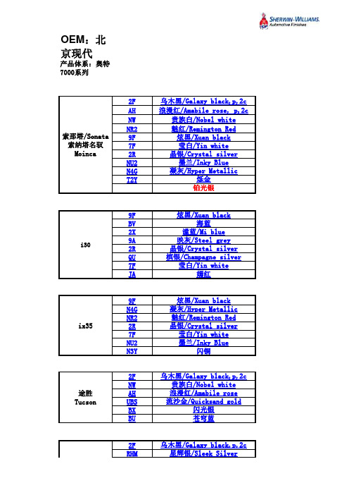
2F NW AH UBS BX BU
乌木黑/Galaxy black,p,2c 贵族白/Nobel white 浪漫红/Amabile rose 流沙金/Quicksand gold 闪光银 苍穹蓝
2F RHM
伊兰特 Elantra
NW
乌木黑/Galaxy black,p,2c 星辉银/Sleek Silver 海黄蓝 铂金银 贵族白/Nobel white
瑞纳 Verna
2F WGM RHM TDY UBS PGU XBG VEA SAE
乌木黑/Galaxy black,p,2c 宝石蓝/Spphire Blue 星辉银/Sleek Silver 魅惑红/Gzrnet Red 流沙金/Stone Beige 优雅白/Crystal White 炫丽黄/Dynamic Yellow 冰河银/Ice Silver 格调灰/Carbon Gray
JB267-TDS-C
EPOWIDE®JB-267 光電製品用環氧樹脂
簡介
JB-267為針對電子製品所開發的熱固化雙液型環氧樹脂。
本樹脂系統具有良好的操作性,並且對於一般塑膠材料以及金屬有優良的接著特性,對多種溶劑和化學品具有優異的抵抗性。
產品特色
1.JB267雙液型環氧樹脂混合後可操作時間長。
2.本樹脂系統具有良好的操作性、易消泡、流動性極佳、表面光澤度良好。
3.用於薄膜或厚膜,若需要應用於較大體積灌注時,推薦在室溫或略高於室溫時變成膠狀體,然後升高溫度完全固化,避免一次升溫反應過於激烈。
樹脂規格
硬化條件
成品性質
儲存環境
應存放在陰涼的處所,曝曬在太陽光下會導致樹脂和硬化劑變黃,應僅量避免。
JA-267B含Imidazole成分,最好是能夠在使用完畢後儘速蓋上蓋子,杜絕任何受潮的可能。
在未開啟原包裝,25℃的儲放條件下,產品的保存期限可長達一年以上。
處置原則
本產品不含致癌物質,但表面接觸可能會導致暫時性的皮膚泛紅,應以肥皂水將受污染的區域清洗乾淨。
吞服JB-267 對人體仍有毒性,一但誤食要馬上送醫診治。
使用者若不小心沾到眼睛時,要立即以大量清水沖洗眼睛至少15分鐘以上再送醫診治。
進一步的注意事項請詳見物質安全資料表。
Everwide Chemical Ltd. Co. 125100318.doc 建立日期2006/2/20 8:20 AM 頁次: 1 / 1
Everwide Chemical Ltd. Co. tds 套表中文建立日期2005/4/7 9:52:00 AM 頁次: 1 / 2。
SINUMERIK ONE 测量循环 编程手册说明书

1.4
技术文档反馈 .............................................................................................................. 13
1.5
mySupport 文档 .......................................................................................................... 14
3 说明............................................................................................................................................... 23
3.10
参数,用于测量结果检查和补偿 .................................................................................. 55
3.11
经验值、平均值和公差参数的影响 ............................................................................... 60
3.5
平面定义,工件类型.................................................................................................... 30
3.6
可使用的测量头........................................................................................................... 34
徕卡M卡口镜头货号、序列号、生产年代、6bit资料查询
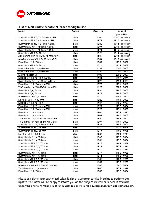
List of 6-bit update capable M lenses for digital useName Colour Order Nr. Year ofpoduction Summicron-M 1:2,0 / 28 mm ASPH. black 11604 2000 - currently Summicron-M 1:2 / 35 mm ASPH. black 11879 1996 - currently Summicron-M 1:2 / 35 mm ASPH. silver 11882 1996 - currently Summilux-M 1:1,4/50 mm ASPH. black 11891 2004 - currently Summilux-M 1:1,4/50 mm ASPH. silver 11892 2006 - currently Summicron-M 1:2/50 mm black 11826 1994 - currently Apo-Summicron-M 1:2,0/75 mm ASPH. black 11637 2005 - currently Apo-Summicron-M 1:2/90 mm ASPH. black 11884 1998 - currently Elmarit-M 1:2,8/90 mm black 11807 1990 - 2007 Summicron-M 1:2/50 mm silver 11816 1994 - 2007 Macro-Elmar-M 1:4,0/90 mm black 11633 2002 - 2007 Macro-Elmar-M 1:4,0/90 mm silver 11634 2002 - 2007 Macro-Adapter M black 14409 2002 - 2007 Elmarit-M 1:2,8/21 mm ASPH. black 11135 1997 - 2011 Summilux-M 1:1,4 / 35 mm ASPH. black 11874 1994 - 2011 Elmarit-M 1:2,8/24 mm ASPH. black 11878 1996 - 2010Tri-Elmar-M 1:4/28-35-50 mm ASPH. black 11625 2000 - 2007 Elmar-M 1:2,8/50 mm black 11831 1995 - 2007 Elmar-M 1:2,8/50 mm silver 11823 1994 - 2007 Summilux-M 1:1,4/75 mm black 11810 1998 - 2007 Noctilux-M 1:1 / 50 mm black 11822 1994 - 2002 Elmarit-M 1:2,8/21 mm black 11134 1980 - 1997 Elmarit-M 1:2,8/21 mm ASPH. silver 11897 1997 - 2004 Elmarit-M 1:2,8/24 mm ASPH. silver 11898 1996 - 2005 Elmarit-M 1:2,8/28 mm black 11804 1979 - 1992 Elmarit-M 1:2,8/28 mm black 11809 1992 - 2005Tri-Elmar-M 1:4/28-35-50 mm ASPH. black 11890 1998 - 2000Tri-Elmar-M 1:4/28-35-50 mm ASPH. silver 11894 1999 - 2000 Summilux-M 1:1,4/35 mm ASPH. silver 11883 1994 - 2004 Summicron-M 1:2/35 mm black 11310 1979 - 1996 Summicron-M 1:2/35 mm silver 11311 1993 - 1996 Noctilux-M 1:1,0/50 mm black 11821 1975 - 1994 Summilux-M 1:1,4/50 mm black 11868 1992 - 2004 Summilux-M 1:1,4/50 mm silver 11856 1992 - 2004 Summicron-M 1:2,0/50 mm black 11817 1969 - 1979 Summicron-M 1:2,0/50 mm black 11819 1979 - 1994 Summicron-M 1:2,0/50 mm silver 11825 1992 - 1994 Summilux-M 1:1,4/75 mm black 11814 1980 - 1982 Summilux-M 1:1,4/75 mm black 11815 1982 - 1998 Summicron-M 1:2,0/90 mm black 11136 1980 - 1989 Summicron-M 1:2,0/90 mm silver 11137 1993 - 1989 Apo-Summicron-M 1:2,0/90 mm ASPH. silver 11885 2002 - 2004 Tele-Elmarit-M 1:2,8/90 mm black 11800 1973 - 1989 Elmarit-M 1:2,8/90 mm silver 11808 1997 - 2004 Please ask either your authorized Leica dealer or Customer Service in Solms to perform the update. The latter will be happy to inform you on this subject. Customer Service is available under the phone number +49 (0)6442 208-189 or via e-mail customer.care@.。
DIN 267-26-2005

Dezember 2005DEUTSCHE NORMNormenausschuss Mechanische Verbindungselemente (FMV) im DINPreisgruppe 7DIN Deutsches Institut für Normung e.V. • Jede Art der Vervielfältigung, auch auszugsweise, nur mit Genehmigung des DIN Deutsches Institut für Normung e. V., Berlin, gestattet.BH#9606629www.din.de Mechanische Verbindungselemente –Technische Lieferbedingungen –Teil 26: Spannscheiben aus Federstahl für SchraubenverbindungenFasteners –Technical specifications –Part 26: Conical spring washers for bolted connectionsÉléments de fixation –Spécifications techniques –Partie 26: Rondelles cuvette emboutie pour assemblages vissés©Alleinverkauf der Normen durch Beuth Verlag GmbH, 10772 BerlinDIN 267-26:1987-10www.beuth.deGesamtumfang 10 SeitenN o r m C D - S t a n d 2005-12DIN 267-26:2005-122VorwortDiese Norm wurde vom Normenausschuss Mechanische Verbindungselemente (FMV), Arbeitsausschuss NA 067-04-02 AA …Scheiben und Ringe“, erarbeitet.Die Norm-Reihe DIN 267 Mechanische Verbindungselemente — Technische Lieferbedingungen , besteht aus folgenden Teilen:— Teil 2: Ausführung und Maßgenauigkeit— Teil 6: Ausführungen und Maßgenauigkeit für Produktklasse F— Teil 13: T eile für Schraubenverbindungen mit besonderen mechanischen Eigenschaften zum Einsatz beiTemperaturen von – 200 °C bis + 700 °C — Teil 24: F estigkeitsklassen für Muttern (Härteklassen)— Teil 27: S chrauben aus Stahl mit klebender Beschichtung — Teil 28: Schrauben aus Stahl mit klemmender Beschichtung— Teil 29: P roduktklassen für Teile für Schraubenverbindungen zum Einsatz bei Temperaturen von– 200 °C bis + 700 °C — Teil 30: Metrische gewindefurchende Schrauben der Festigkeitsklasse 10.9 ÄnderungenGegenüber DIN 267-26:1987-10 wurden folgende Änderungen vorgenommen: a) Titel geändert;b) Anwendungsbereich auf Spannscheiben beschränkt; c) Normative Verweisungen aktualisiert;d) Maximale Scheibenhärte auf 490 HV begrenzt, um die Gefahr der Wasserstoffversprödung zu ver-mindern; e) Mindestscheibenhöhe nach Entlastung bei Spannscheiben für Kombi-Schrauben entsprechendDIN 6908:1995-08 korrigiert; f)Anpresskräfte für Federkraftprüfung erhöht;g) Restfederkräfte nicht mehr nur als Anhaltswerte gekennzeichnet;h) Prüfvorrichtung für Federkraftprüfung in normativen Anhang A aufgenommen; i)Ermittlung der Federkennlinie in normativen Anhang B aufgenommen.Frühere Ausgaben DIN 267-26: 1987-10N o r m C D - S t a n d 2005-12--``,,,,,,`,`,`,``,,`,``,```,`-`-`,,`,,`,`,,`---DIN 267-26:2005-1231 AnwendungsbereichDiese Technischen Lieferbedingungen gelten für Spannscheiben aus Federstahl für Schraubenverbindungen nach folgenden Normen:⎯ DIN 6796, Spannscheiben für Schraubenverbindungen ⎯ DIN 6908, Spannscheiben für Kombi-SchraubenEs wird empfohlen, diese Technischen Lieferbedingungen sinngemäß auch für nichtgenormte Spannscheiben aus Federstahl für Schraubenverbindungen anzuwenden.Spannscheiben aus anderen Werkstoffen als Federstahl sind von dieser Norm nicht erfasst.ANMERKUNG Mitverspannte Spannscheiben aus Federstahl erfüllen die Aufgabe, einen durch Setz- und/oder Kriech-vorgänge hervorgerufenen Vorspannkraftverlust zu kompensieren, wenn sie⎯ eine ausreichende elastische Nachgiebigkeit besitzen, um die Nachgiebigkeit der gesamten Schraubenverbindung zuvergrößern und ⎯ eine ausreichende Federkraft besitzen, die einen auftretenden Vorspannkraftverlust so weit ausgleichen kann, dassdie für die Betriebssicherheit der Schraubenverbindung erforderliche Klemmkraft erhalten bleibt.Wird der Reibschluss zwischen den verspannten Teilen durch Querkräfte überwunden, können Relativbewegungen zwischen Schraube und Mutter entstehen. In solchen Fällen ist ein Losdrehen der Verbindung durch mitverspannte Spannscheiben im Allgemeinen nicht zu verhindern.Beim Einsatz von Spannscheiben unter solchen Bedingungen sollte deshalb geprüft werden, ob die Voraussetzung für eine zweckmäßige Verwendung als klemmkrafterhaltendes Element gegeben ist.2 Normative VerweisungenDie folgenden zitierten Dokumente sind für die Anwendung dieses Dokuments erforderlich. Bei datierten Ver-weisungen gilt nur die in Bezug genommene Ausgabe. Bei undatierten Verweisungen gilt die letzte Ausgabe des in Bezug genommenen Dokuments (einschließlich aller Änderungen).DIN 879-1, Prüfen geometrischer Größen — Feinzeiger — Teil 1: Mit mechanischer Anzeige DIN 6796, Spannscheiben für Schraubenverbindungen DIN 6908, Spannscheiben für Kombi-SchraubenDIN EN 10089, Warmgewalzte Stähle für vergütbare Federn — Technische LieferbedingungenDIN EN 10132-4, Kaltband aus Stahl für eine Wärmebehandlung — Technische Lieferbedingungen — Teil 4: Federstähle und andere AnwendungenDIN EN ISO 3269, Mechanische Verbindungselemente — Annahmeprüfung DIN EN ISO 4042, Verbindungselemente — Galvanische ÜberzügeDIN EN ISO 6507-1, Metallische Werkstoffe — Härteprüfung nach Vickers — Teil 1: PrüfverfahrenDIN EN ISO 6508-1, Metallische Werkstoffe — Härteprüfung nach Rockwell (Skalen A, B, C, D, E, F, G, H, K, N, T) — Teil 1: PrüfverfahrenDIN EN ISO 18265, Metallische Werkstoffe — Umwertung von HärtewertenVDI 2230-1:2003, Systematische Berechnung hochbeanspruchter Schraubenverbindungen — Zylindrische EinschraubenverbindungenN o r m C D - S t a n d 2005-12DIN 267-26:2005-1243 Allgemeine AnforderungenFür die Wirksamkeit mitverspannter Spannscheiben bei Schraubenverbindungen sind ⎯ der Werkstoff (siehe Abschnitt 4) und⎯ die Erfüllung der Prüfkriterien nach Abschnitt 5 entscheidend.Die Spannscheiben müssen eine glatte Oberfläche aufweisen und frei von Zunder und Grat sein. Rauhtiefen der Oberflächen sind erforderlichenfalls in den Produktnormen anzugeben. Die Spannscheiben sind gegen Anrosten geschützt zu liefern.Für galvanische Überzüge gilt DIN EN ISO 4042.ANMERKUNG Bei den heute bekannten Verfahren zum Abscheiden von Metallüberzügen aus wässrigen Lösungen ist bei Spannscheiben ein wasserstoffinduzierter verzögerter Sprödbruch nicht auszuschließen (siehe hierzu DIN EN ISO 4042). Bei Teilen mit Härten ≥ 400 HV besteht eine erhöhte Sprödbruchgefahr. Deshalb sind hier in Bezug auf Werkstoffauswahl, Wärme- und Oberflächenbehandlung besondere Maßnahmen erforderlich.4 WerkstoffFederstahl (FSt) nach DIN EN 10089 oder DIN EN 10132-4 oder gleichwertiger Federstahl; Sorte nach Wahl des Herstellers. Dieser Werkstoff gilt auch, wenn in vorhandenen Unterlagen kein Werkstoff genannt ist. Ge-härtet und angelassen müssen Spannscheiben für Schraubenverbindungen eine Härte von 420 HV bis 490 HV aufweisen.5 Prüfung5.1 Prüfung auf Maßhaltigkeit und AusführungFür die Annahmeprüfung im Hinblick auf Maßhaltigkeit von Spannscheiben für Schraubenverbindungen gelten die Festlegungen in DIN EN ISO 3269 sinngemäß, wobei für die Merkmale ⎯ Innendurchmesser, ⎯ Scheibendicke, ⎯ ungespannte Höhe und ⎯ Außendurchmesser der AQL-Wert 1,5 gilt.5.2 Prüfung der mechanischen Eigenschaften5.2.1 AllgemeinesDie mechanischen Eigenschaften werden nach 5.2.2 bis 5.2.5 geprüft. 5.2.2 HärteprüfungFür die Härteprüfung nach Vickers gilt DIN EN ISO 6507-1. Für die Härteprüfung nach Rockwell gilt DIN EN ISO 6508-1.Für die Umwertung von Härtewerten gilt DIN EN ISO 18265.N o r m C D - S t a n d 2005-12--``,,,,,,`,`,`,``,,`,``,```,`-`-`,,`,,`,`,,`---DIN 267-26:2005-125Bei Spannscheiben wird möglichst in der Mitte der Ringfläche gemessen. Es ist für eine feste Auflage im Be-reich der Messstelle zu sorgen. 5.2.3 SetzprüfungDie zu prüfenden Spannscheiben sind zwei Minuten lang mit den in der Tabelle 1 angegebenen Anpress-kräften zusammenzudrücken.ANMERKUNG Die Anpresskräfte entsprechen den Vorspannkräften für Schrauben der Festigkeitsklasse 8.8 bei µG = 0,12 nach VDI 2230-1:2003.Nach dem Entlasten darf die Höhe der Spannscheiben die in der Tabelle 1 angegebenen Mindestmaße nicht unterschreiten.5.2.4 DauerbelastungsversuchZehn durch planparallele Scheiben (vergütet auf mindestens 500 HV) voneinander getrennt und wechselseitig auf einem Bolzen aufgereihte Spannscheiben dürfen nach 48-stündigem Zusammendrücken mit den Anpresskräften nach der Tabelle 1 bei einer Temperatur von + 100 °C weder brechen, noch darf nach dem Entlasten die in der Tabelle 1 angegebene Mindest-Scheibenhöhe um mehr als 2 % unterschritten werden.Tabelle 1 — SetzprüfungNenngröße(Schrauben-Nenndurchmesser)2 2,53 3,5456 Anpresskraft akN0,92 1,54 2,35 3,16 4,4 7,2 10,2DIN 6796 0,5 0,6 0,7 0,9 1,1 1,3 1,7 Mindest-Scheiben-höhe nach Entlastungmm DIN 6908b — 0,61 0,72 0,92 1,12 1,35 1,70Nenngröße(Schrauben-Nenndurchmesser)7 8 10 12 14 16 18 Anpresskraft akN14,8 18,6 29,6 43 59,1 80,9 102DIN 6796 2 2,2 2,8 3,4 4 4,6 5,1 Mindest-Scheiben-höhe nach Entlastungmm DIN 6908 b — 2,24 2,8 3,43———Nenngröße(Schrauben-Nenndurchmesser)20 22 24 27 30 Anpresskraft akN130 162 188 246 300DIN 6796 5,6 6,1 6,8 7,3 8 Mindest-Scheiben-höhe nach Entlastungmm DIN 6908b — — — — —a Anpresskraft entsprechend Vorspannkraft für Schrauben der Festigkeitsklasse 8.8 bei µG= 0,12 nach VDI 2230-1.b Abweichend von den Angaben in der Produktnorm für Spannscheiben für Kombi-Schrauben ist die maßgebendeNenngröße der Schrauben-Nenndurchmesser und nicht der Lochdurchmesser der Spannscheibe.N o r m C D - S t a n d 2005-12--``,,,,,,`,`,`,``,,`,``,```,`-`-`,,`,,`,`,,`---DIN 267-26:2005-1265.2.5 FederkraftprüfungZur Beurteilung der elastischen Nachgiebigkeit von Spannscheiben ist eine Federkraftprüfung durchzuführen. Bei dieser werden Restfederkräfte ermittelt.Das zu prüfende Element wird in eine Vorrichtung eingelegt und mit der Anpresskraft nach Tabelle 2 belastet. Die Prüfeinrichtung muss so gestaltet sein, dass die Kraft möglichst gleichmäßig aufgebracht werden kann. Die Prüfplatte muss eine Oberflächenhärte von mindestens 60 HRC aufweisen. Die auf das Federelement aufgebrachte Kraft wird nach zwei Minuten langsam und stetig um einen Federweg von 20 µm zurückge-nommen. Für die Prüfung des Messweges müssen Präzisionsmessgeräte eingesetzt werden. Die Restfeder-kraft nach einem Federweg von 20 µm muss die Mindestwerte nach Tabelle 2 erreichen. Die Verformung der Prüfvorrichtung ist zu berücksichtigen.Eine geeignete Prüfvorrichtung ist in Anhang A beschrieben.Festlegungen zur Ermittlung der Federkennlinien sind in Anhang B enthalten. Die Tabelle 3 gibt eine Übersicht über die geforderten Restfederkräfte.Tabelle 2 — Mindest-RestfederkräfteNenngröße a 4 5 6 7 8 10 12 14 16 Anpresskraft bkN 4,4 7,2 10,2 14,8 18,6 29,6 43 59,1 80,9 Mindest-RestfederkraftkN1,4 2,3 4,2 6,2 7,7 12,4 18 25 34Nenngröße a 18 20 22 24 27 30 Anpresskraft bkN 102 130 162 188 246 300 Mindest-RestfederkraftkN57 73 91 122 161 196a Abweichend von den Angaben in DIN 6908 ist bei Spannscheiben für Kombi-Schrauben die maßgebende Nenn-größe der Schrauben-Nenndurchmesser und nicht der Lochdurchmesser der Spannscheibe.b Anpresskraft entsprechend Vorspannkraft für Schrauben der Festigkeitsklasse 8.8 bei µG= 0,12 nach VDI 2230-1.Tabelle 3 — Restfederkräfte (Übersicht)Benennung Norm Anpresskraft entsprechendder Vorspannkraftfür FestigkeitsklasseRestfederkraftnach 20 µm Entlastungswegin % der Anpresskraft Spannscheibe DIN 6796 DIN 69088.835 % für Nenngrößen 4 bis 5 45 % für Nenngrößen 6 bis 16 60 % für Nenngrößen 18 bis 22 70 % für Nenngrößen > 22N o r m C D - S t a n d 2005-12DIN 267-26:2005-1276 LieferartSpannscheiben aus Federstahl für Schraubenverbindungen sind so zu verpacken, dass sie gegen mecha-nische Schäden auf dem Transport weitgehend geschützt sind.Abgepackte Teile müssen auf der Packung die Kurzbezeichnung nach der jeweiligen Norm tragen, z. B.DIN 6796 — 8 — FStFerner sind die Stückzahl und das Herstellerzeichen anzugeben.N o r m C D - S t a n d 2005-12--``,,,,,,`,`,`,``,,`,``,```,`-`-`,,`,,`,`,,`---DIN 267-26:2005-128Anhang A (normativ)Prüfvorrichtung für die FederkraftprüfungA.1 AllgemeinesDie in Bild A.1 dargestellte Prüfvorrichtung ist ein Beispiel für eine geeignete Ausführung. Andere Ausfüh-rungen sind zulässig.Die in A.2 festgelegten Anforderungen an die Prüfvorrichtung sind jedoch einzuhalten.Legende1 Druckstempel2 Aufnahmeplatte3 Zentrier-Zylinderstifte4 Taststift5 Zentrierung6 Ständer7 Hülse8 WegmessgerätBild A.1 — Beispiel für eine PrüfvorrichtungN o r m C D - S t a n d 2005-12DIN 267-26:2005-129A.2 Anforderungen an die Prüfvorrichtunga) Geringe Nachgiebigkeit, möglichst nur (elastische) Druckverformungen und keine Biegeverformungeninsbesondere im Bereich des Kraftflusses in Druckstempel (1), Aufnahmeplatte (2) und oberem Teil des Ständers (6). b) Mittige Bohrung im Ständer zur Durchführung des Taststiftes (4) des Wegmessgerätes (8) und derHülse (7). c) Befestigung des Wegmessgerätes (8) mittels einer Hülse (7) direkt in Höhe der Spannscheibenauflageauf der Aufnahmeplatte (2), damit die durch Eigenverformung des Messgerätes bedingten Fehler mög-lichst klein werden. d) Aufnahmeplatte (2) mit Hülse (7) auswechselbar, um Aufnahmeplatten für verschiedene Durchmesserbenutzen zu können. e) Alle Flächen, die im Kraftfluss liegen und deren elastische Verformungen in die Wegmessung eingehen,müssen eine Rauheit von R a ≤ 0,4 (etwa R z ≤ 1,6) haben. f)Die Aufnahmeplatte (2) und der Druckstempel (1) müssen eine Härte ≥ 60 HRC haben.g) Der Druckstempel (1) muss parallel zur Auflageplatte geführt werden; es ist zweckmäßig, wenn derStempel um einige 1/10 mm bei geringen elastischen Kräften in der Ebene der Auflageplatte ausweichen kann. Im Allgemeinen ist dies bei Universalprüfmaschinen gegeben. h) Die Anpresskraft muss mit einer Messunsicherheit von 2 % einstellbar und die Restfederkraft auf 2 %ablesbar sein. i)Der Feinzeiger, der induktive Wegaufnehmer oder andere Wegmessgeräte (8) dürfen in jedem beliebigen Teilanzeigebereich von 40 µm höchstens eine Abweichungsspanne und Umkehrspanne von 1 µm haben, und zwar bei herausgehendem Taststift (Definitionen siehe DIN 879-1).N o r m C D - S t a n d 2005-12--``,,,,,,`,`,`,``,,`,``,```,`-`-`,,`,,`,`,,`---DIN 267-26:2005-1210Anhang B (normativ)Ermittlung der FederkraftkennlinieBei der Ermittlung der wahren Federkraftkennlinie von Spannscheiben im Rahmen der Federkraftprüfung muss der Einfluss der elastischen Eigenverformung der Prüfeinrichtung eliminiert werden, indem der von der Prüfvorrichtung herrührende Federweg vom Gesamtfederweg (Federelement + Prüfvorrichtung) abgezogen wird. Die Entlastungskennlinie der Prüfvorrichtung wird wie folgt ermittelt:In die Prüfvorrichtung (Beispiel siehe Bild A.1) wird anstelle des Federelementes eine beidseitig geläppte Scheibe eingelegt, die eine Parallelitätstoleranz von ≤ 1 µm und eine Härte ≥ 700 HV aufweist, und deren Werte für Lochdurchmesser, Außendurchmesser und Dicke gleich denen der zu prüfenden Spannscheibe sind. Ausgehend von der Anpresskraft nach Tabelle 2 wird die Entlastungskennlinie der Vorrichtung aufge-zeichnet.ANMERKUNG Bei der Aufnahme der Entlastungskennlinie der Prüfvorrichtung ist die Verwendung der planparallelen Scheibe mit gleichem Durchmesser und gleicher Dicke wie die zu prüfende Spannscheibe sehr wesentlich, da Scheiben mit anderen Maßen andere Vorrichtungs-Entlastungskennlinien ergeben.In Bild B.1 ist schematisch die Gesamt-Entlastungskennlinie (Spannscheibe + Prüfvorrichtung) als durchge-zogene Kurve und die Entlastungskennlinie mit der Prüfvorrichtung als gestrichelte Kurve aufgetragen. Ein Stück der durch Subtraktion der beiden Kurven ermittelten wahren Entlastungskennlinie der Spannscheibe ist als strichpunktierte Kurve eingezeichnet.Um bei der Prüfung einen eventuellen Umkehrfehler der Weg- und Kraft-Messeinrichtungen zu verhindern, ist es zulässig, beim Belasten 5 % über die Anpresskräfte nach Tabelle 2 hinauszugehen. Der Entlastungswegvon 20 µm darf jedoch immer erst ab der vorgeschriebenen Anpresskraft ermittelt werden.a Gesamt-Entlastungskennlinieb Entlastungskennlinie der Prüfvorrichtungc Entlastungskennlinie der Spannscheibed Ermittelte Restfederkraft X nach Entlastung der Spannscheibe um 20 µmBild B.1 — Beispiel für die Ermittlung der Federkraftkennlinie (Entlastungskennlinie)N o r m C D - S t a n d 2005-12--``,,,,,,`,`,`,``,,`,``,```,`-`-`,,`,,`,`,,`---。
- 1、下载文档前请自行甄别文档内容的完整性,平台不提供额外的编辑、内容补充、找答案等附加服务。
- 2、"仅部分预览"的文档,不可在线预览部分如存在完整性等问题,可反馈申请退款(可完整预览的文档不适用该条件!)。
- 3、如文档侵犯您的权益,请联系客服反馈,我们会尽快为您处理(人工客服工作时间:9:00-18:30)。
Severe Ice Conditions in the Bohai Sea,China,and Mild Ice Conditionsin the Great Lakes during the 2009/10Winter:Links to El Nin ˜oand a Strong Negative Arctic Oscillation*X UEZHI B AICooperative Institute for Limnology and Ecosystems Research,University of Michigan,Ann Arbor,MichiganJ IA W ANGNOAA Great Lakes Environmental Research Laboratory,Ann Arbor,MichiganQ INZHENG L IUNational Marine Environmental Forecasting Center,State Oceanic Administration,Beijing,ChinaD ONGXIAO W ANGSouth China Sea Institute of Oceanology,Chinese Academy of Sciences,Guangzhou,ChinaY U L IUNational Marine Environmental Forecasting Center,State Oceanic Administration,Beijing,China(Manuscript received 12October 2010,in final form 21February 2011)ABSTRACTThis study investigates the causes of severe ice conditions over the Bohai Sea,China,and mild ice cover over the North American Great Lakes under the same hemispheric climate patterns during the 2009/10winter witha strong negative Arctic Oscillation (AO)and an El Nin˜o event.The main cause of severe ice cover over the Bohai Sea was the strong negative AO.Six of seven winters with severe ice were associated with a strong negative AO during the period 1954–2010.The Siberian high (SH)in the 2009/10winter was close to normal.Theinfluence of El Nin˜o on the Bohai Sea was not significant.In contrast,the mild ice conditions in the Great Lakes were mainly caused by the strong El Nin˜o event.Although the negative AO generally produces significant colder surface air temperature (SAT)and heavy ice cover over the Great Lakes,when it coincided witha strong El Nin˜o event during the 2009/10winter the El Nin ˜o–induced Pacific–North America (PNA)-like pattern dominated the midlatitudes and was responsible for the flattening of the ridge–trough system over North America,leading to warmer-than-normal temperatures and mild ice conditions over the Great Lakes.This comparative study revealed that interannual variability of SAT in North America,includingthe Great Lakes,is effectively influenced by El Nin˜o events through a PNA or PNA-like pattern whereas the interannual variability of SAT in northeastern China,including the Bohai Sea area,was mainly controlled by AO and SH.1.IntroductionThe Arctic Oscillation (AO)was defined by Thompson and Wallace (1998)as the leading empirical orthogonal function (EOF)mode of wintertime sea level pressure (SLP)anomalies over the extratropical Northern Hemi-sphere.The AO has an out-of-phase pattern in atmo-spheric pressure between the Arctic Basin and middle*Great Lakes Environmental Research Laboratory Contribution Number 1585.Corresponding author address:Xuezhi Bai,Cooperative In-stitute for Limnology and Ecosystems Research,University of Michigan,Ann Arbor,MI 48108.E-mail:xuezhi@ DOI:10.1175/2011JAMC2675.1Ó2011American Meteorological Societylatitudes.It is shown to exert a strong influence on win-tertime climate at virtually all longitudes(Thompson and Wallace2001),including far eastern Asia(Gong and Ho2003;Yu and Zhou2004;Li et al.2008).In associ-ation with AO,a surface atmosphere temperature(SAT) anomaly typically swings between Eurasia–Arctic Ocean and the Labrador Sea–eastern Canada(van Loon and Rogers1978;Wang et al.1994;Mysak et al.1996; Wang and Ikeda2000).During a negative phase of AO,higher-than-normal atmospheric pressure over the Arctic induces weaker westerly winds in the upper atmosphere,which allows cold Arctic air to reach more southerly latitudes,resulting in a colder winter in the United States but warmer weather in northeastern Canada(Hodges2000).The North Ameri-can Great Lakes usually experience a colder winter.For the Eurasian continent,a negative AO is generally asso-ciated with warmer subtropical but colder mid–high lati-tudes(Yu and Zhou2004;Li et al.2008).Thus,during the negative phase of AO,the Bohai Sea in China(located off northeastern China,378–418N,1178–1238E)(Fig.1a)and the Great Lakes in North America(418–498N,758–928W) (Fig.1b)are usually both expected to have higher-than-normal ice cover(Bai et al.2010).In the2009/10winter with a very strong negative AO(winter mean index5 23.5),however,the Bohai Sea experienced severe ice cover(the greatest in30years)while the Great Lakes underwent a very mild ice season.The2009/10winter was also a strong El Nin˜o winter,with the December–February(DJF)mean Nin˜o-3index being 1.18C.The event developed in the autumn of2009and persisted through winter.North America is significantly influenced by El Nin˜o via the Pacific–North America (PNA)pattern(Wallace and Gutzler1981).The well-known pattern,associated with El Nin˜o,features above-normal SAT along the west coast of North America and western and central Canada and below-normal SAT in the southern United States and the Gulf of Mexico.The Great Lakes also experience warm winters during El Nin˜o events. During the2009/10winter,a strong negative AO and a strong El Nin˜o event occurred simultaneously.The Bohai Sea and the Great Lakes experienced dramatically different ice conditions that did not follow usual conditions in strong negative AO years.This paper discusses this observation from the perspective of joint AO and El Nin˜o–Southern Oscillation(ENSO)forcing.The causes of severe ice con-ditions over the Bohai Sea and mild ice on the Great Lakes in response to the same climate patterns were investigated.2.DataThe data used here include monthly-mean temperatures from160stations in China for the period from1951to2010 from the China Meteorological Administration(CMA), and monthly-mean SLP,SAT,surface-level and700-hPa-level winds,and500-hPa geopotential height for the period 1948–2010from the National Centers for Environmental Prediction reanalysis dataset(Kalnay et al.1996).The cli-matological monthly means of the period from1949to 2010were calculated and then subtracted from the indi-vidual months to obtain the monthly anomalies. Monthly AO and Nin˜o-3indices for the years1950–2010were taken from the National Oceanic and At-mospheric Administration(NOAA)ClimatePrediction F IG.1.Locations of(a)the Bohai Sea,China,and(b)the Great Lakes in North America.Center.The AO index is defined by the first EOF mode of SLP north of 208N in the Northern Hemisphere.The Nin˜o-3index is defined as the 3-month running mean of sea surface temperature anomalies in the Nin˜o-3region (58N–58S,1508–908W).The east Asian winter monsoon (EAWM)index is defined as the normalized SLP dif-ference between 1108and 1608E within 208–508N (Shi et al.1996).The Siberian high (SH)intensity index is defined as the regionally averaged SLP (408–608N,808–1208E),following the method of Wu and Wang (2002).In 1973,the State Oceanic Administration (SOA)of China defined five categories (scales)of sea ice severity according to the ice thickness and extent in the Bohai Sea and northern Yellow Sea based on the observed data since 1963.The five categories range from 1.0to 5.0.Category I represents the lightest ice severity,V is the most severe (most of the sea is covered by sea ice),III represents the normal severity,and II and IV denote the moderately light and moderately heavy severity,re-spectively.Figure 2shows the ice edges correspond-ing to the ice categories.The ice category is evaluated by the weighted sum of ice scales of three bays.The weighted coefficients are 0.5,0.3,and 0.2,respectively,for Liaodong Bay,Bohai Bay,and Laizhou Bay (Bai et al.2001).In this study,the sea ice severity index was taken from Bai et al.(2001)and Gong et al.(2007).The updated data were from SOA’s Annual Bulletin of Ocean Di-sasters.The sea ice severity time series covers winters for the period 1953/54–2009/10(Fig.3).The long-term mean sea ice severity index for the period 1953/54–2009/10is 2.57.Thus,the climatological ice edge is between line II and line III (diagonally striped area in Fig.2).Measurements from the Moderate Resolution Imaging Spectroradiometer (MODIS)on board the National Aeronautics and Space Administration (NASA)Terrasatellite during the 2009/10winter were also used to study the extreme sea ice event in the Bohai Sea.An index of winter severity (WSI)over the Bohai Sea area was defined as the average of the monthly-mean temperatures from November through February at six stations around the Bohai Sea:Tianjin,Yingkou,Dalian,Weifang,Yantai,and Chaoyang (Table 1).Monthly-mean temperatures for the six stations obtained from CMA were used to calculate the winter severity index for winters from 1951/52to 2009/10,as shown along with the Bohai Sea ice severity index in Fig.3.Annual maximum ice coverage (AMIC)is defined as the greatest percentage of surface area of a lake covered by ice each winter for the Great Lakes.Figure 4shows the spatial distribution of the 30-yr (1973–2002)mean annual maximum ice cover.The map was constructed by two steps:first,the date and magnitude of the AMIC were identified for the Great Lakes as a whole for each of these winters based on analysis of daily spatial average ice cover of the entire Great Lakes as given in Assel (2003);second,the mean ice cover concentration for the 30AMIC dates was calculated at each grid cell.TheAMICF IG .2.Ice edges corresponding to the ice categories (I,II,III,etc.)in the Bohai Sea,China.Thediagonally striped area denotes the climatological icecover.F IG .3.Time series of the Bohai Sea ISI (bars)and WSI (black line with filled circles)for winters 1954–2010.The 0-lag correlation coefficient is also shown.for the Great Lakes as a whole for winters1963–2010was calculated using the dataset obtained from the National Snow and Ice Data Center(Fig.5).The long-term mean (1963–2010)AMIC is54.5%,and the standard deviation is 21%.In this analysis,winters with normalized AMIC of greater than or equal to0.7($69%)were identified as maximal-ice-cover winters,and winters with normalized AMIC of less than or equal to20.7(#40%)were iden-tified as minimal-ice-cover winters.In an earlier study(Quinn et al.1978),C.R.Snider developed an index of Great Lakes winter severity.It is defined as the average of the monthly-mean temper-atures from November through February at Duluth, Minnesota;Sault Ste.Marie and Detroit,Michigan;and Buffalo,New York(see Table1for station information), which was found to correlate with the mass of ice for-mation on the Great Lakes.In this study,monthly-mean temperature for the four stations obtained from Na-tional Climatic Data Center was used to calculate winter severity index for the period from1963to2010,which was shown along with AMIC in Fig.5.The Bohai Sea is a semienclosed and very shallow sea (average depth is about20m),and the local weather plays an essential role in sea ice conditions.Observations in-dicated that the dynamical factors such as wind stress and surface ocean currents are not so important in the distri-bution of sea ice(Zhang1986).The correlation between the time series of Bohai sea ice severity index and winter severity index for the winters of1954–2010was20.81(Fig.3),which is significant at the99%confidence level.Great Lakes ice conditions are also mainly governed by surface air temperature.The correlation between the AMIC and Great Lakes winter severity was20.79for the winters of 1963–2010(Fig.5),which is also significant.In this study, we do not address the influence of wind-related ice dy-namics;we only focus on the temperature influences.3.Resultsa.Synoptic description of the2009/10ice seasonIn contrast to the recent warm winters since the1980s, the Bohai Sea experienced severe ice cover in the win-ter of2010.The maximum ice coverage occurred on 23January2010with51%of the Bohai Sea being cov-ered by ice(China Daily,27January2010)(Fig.6a). On26January,the maximum ice thickness was40,25, and20cm in Liaodong Bay,Bohai Bay,and LaizhouT ABLE1.Meteorological stations(WMO5World MeteorologicalOrganization).Name WMO code Lat Lon Alt(m)Tianjin5452739.088N117.078E 2.5Yingkou5447140.678N122.278E 3.3Dalian5466238.908N121.638E91.5Weifang5484336.758N119.188E22.2Yantai5475137.538N121.408E47.0Chaoyang5432441.558N120.458E169.9Detroit,MI7253742.238N83.338W202.0Sault Ste.Marie,MI7273446.478N84.378W220.1Buffalo,NY7252842.938N78.738W215.0Duluth,MN7253742.838N92.188W432.0F IG.4.Long-term(1973–2002)mean AMIC in the Great Lakes.Bay,respectively (China Daily,27January 2010).On 13February,Liaodong Bay was almost completely covered by ice (Fig.6b).The ice conditions were some of the most severe in the last 30years and were defined as category 4.Since 1954,there were seven winters (1956,1957,1968,1969,1977,2001,and 2010)with an ice se-verity index of equal to or greater than category 4.The most recent two years were 2001and 2010(Fig.3).Al-though both were defined as category 4,ice conditions during the winter of 2010were a little more severe than those during the winter of 2001:Annual maximum ice coverage and its duration in winter 2010were a little greater and longer than those in 2001.In contrast,the Great Lakes of North America expe-rienced a very mild winter.The AMIC in Lake Superior was only 27.1%.Lakes Michigan,Huron,and Ontario had 22.6%,35.7%,and 14.2%,respectively,with Lake Erie being an exception with an AMIC of 89.5%.The average AMIC for all lakes was 26.6%,which occurred on 9February 2010(Fig.6c).Ice cover in the 2009/10winter was the fifth mildest since 1963(Fig.5).The long-term mean and standard deviation of AMIC of each lake for the period from 1973to 2010are listed in Table 2.The normalized AMICs in Lakes Superior,Michigan,Huron,Erie,and Ontario during the 2010winter were 21.23,20.75,21.14,0.24,and 20.64,respectively.Ice cover over Lakes Superior and Huron was greatly reduced.During December of 2009,a typical negative AO pat-tern dominated the Northern Hemisphere,with above-normal heights over the polar region and below-normal heights over the middle latitudes,with two centers over the North Pacific and the North Atlantic Oceans (Fig.7a).Monthly-mean 500-hPa height shows an expanded cir-cumpolar vortex with three low centers over the Cana-dian Maritimes and Hudson Bay,the western Siberian Plain,and the Sea of Okhotsk.The positions of these three lows were well south of their usual latitudes,which were favorable for advecting cold Arctic air to southern latitudes,leading to cold temperatures there.In particu-lar,over North America,there was a deep trough fromHudson Bay all the way to the southwest and a strong ridge over the West Coast off Canada and Alaska (Fig.7a).This amplified ridge–trough system led to an extremely cold December in southwestern Canada andalmostF IG .5.Great Lakes (GL)AMIC (solid line with open circles)and WSI (dashed line with plus signs)for winters 1963–2010.The 0-lag correlation coefficient is alsoshown.F IG .6.(a)AMIC over the Bohai Sea on 23Jan 2010as measured by MODIS on board NASA’s Terra satellite;(b)ice cover on 13Feb 2010as measured by MODIS;(c)AMIC over the Great Lakes on 9Feb 2010as measured by a blend of observations (ships,shore,aircraft,and satellite).the entire United States.The greatest negative anomaly was as much as268C(Fig.8a).The warm advection downstream of the deep troughs led to above-normal temperatures in Alaska,much of Canada,and the northeast area in the United States,including the Great Lakes.The Great Lakes area was slightly warmer than normal,with SAT anomaly ranging from08to28C(Fig. 8a).Over Eurasia,cold advection associated with the polar low over the western Siberian Plain led to a large cooling in northern Asia with a center in western and central Siberia(Fig.8a).The cooling covered much of China except for the southwestern area.Temperatures were0.58–1.58C below normal in the Bohai Sea area. The Bohai Sea WSI was23.58C.This global SAT anomaly pattern is similar to the regression map of SAT upon negative AO index and will be discussed shortly. The500-hPa height anomaly in January of2010shows a positive PNA-like pattern dominating the midlatitudes, with negative anomalies over the Gulf of Alaska and over the southeastern United States and central Atlantic and positive anomalies over Hudson Bay and the Great Lakes(Fig.7b).This pattern resembles a positive PNA pattern,but the locations of anomaly centers were well east of the classical PNA pattern.These anomalies reflected a stronger trough over the Gulf of Alaska and a much weaker Hudson Bay trough.The Aleutian lowT ABLE2.Long-term mean and standard deviations(STD)of AMIC of each Great Lake for the period1973–2010.Superior Michigan Huron Erie Ontario Mean63.3%38.6%62.7%83.7%26.8% STD29.4%21.3%23.6%24.4%19.7% STD/mean0.460.550.380.290.74was somewhat southeast of its normal position (not shown).These conditions allowed warm and humid air from the Pacific Ocean to flow into high latitudes,re-sulting in above-normal temperatures in southern Alaska,Canada,and the northern United States,including the Great Lakes region.The SAT anomaly in the Great Lakes ranged from 21.58to 38C.The upper lakes were warmer than normal while Lake Erie and southern Lake Michigan were colder than normal (Fig.8b).Thus,Lake Erie was heavily ice covered while the other lakes had mild ice cover (Fig.6c).There was also a negative North Atlantic Oscillation (NAO)pattern with above-normal heights across the high latitudes of the North Atlantic and below-normal heights over the central North Atlantic,the eastern United States,and western Europe.The en-hanced blocking over Greenland prevented the usual warmer,damper,westerly winds from reaching Europe across the Atlantic,pushing large amounts of cold Arctic air from the north,and resulting in significant cooling in northern Eurasia with a center of 88C below normal in Siberia (Fig.8b).In Asia,the polar low center over the western Siberian Plain in December 2009disap-peared.Above-normal heights occupied much of Asia except for below-normal heights over the Lake Baikal region.The northwest Pacific subtropical high was strong and was located north of its normal position (not shown).Monthly-mean temperature over much of China was 18–48C above normal,and air temperatures were 18–28C below normal in northern north China,eastern inner Mongolia,and southern northeast China (China Climate System Monitoring Bulletin,January 2010).The SAT anomaly in the Bohai Sea ranged from 21.08F IG .8.Surface air temperature (color shaded;8C)and surface wind (vectors;m s 21)anomaliesfor (a)December 2009,(b)January 2010,and (c)February 2010.to21.58C(Fig.8b).The Bohai Sea WSI was26.358C in January.During February2010,the anomalous500-hPa heights reflected a mixture of AO,NAO,and PNA-like patterns. The centers of the PNA-like pattern shifted westward (Fig.7c)a little in comparison with that during January 2010(Fig.7b).Similar to December2009,the monthly-mean500-hPa heights show an expended circumpolar vortex with an Arctic cold air mass being pushed south-ward.Three low centers were over eastern Canada, Scandinavia,and eastern Siberia,respectively(Fig.7c). Consistent with this anomalous circulation pattern,the main temperature signals in North America include above-normal temperatures across Canada and Alaska and below-normal temperatures in the central and east-ern United States.The Great Lakes were between,with warming in the upper lakes and cooling in the lower lakes(Fig.8c).In Asia,the amplified blocking over the Ural Mountains and the strong low center over eastern Siberia(Fig.7c)pushed Arctic cold air southward,re-sulting in significant cooling in northern Asia with the center in western Siberia(Fig.8c).The cooling was mainly north of408N.The temperatures in northeast China and Xinjiang(northwest tip in China)were18–48C below normal while the temperatures in most of China were18–48C above normal(China Climate System Mon-itoring Bulletin,February2010).Temperature anomalies in the Bohai Sea area were from20.58to10.58C with warming in the south and cooling in the north(Fig.8c). The Bohai Sea WSI was22.678C.As MODIS pictures during February show(Fig.6b),the ice over Laizhou and Bohai Bays in the south was almost melted while the ice over Liaodong Bay in the north kept growing and cov-ered almost the entire bay.Average winter(November–February)surface tem-perature for six stations(Table1)around the Bohai Sea in the2009/10winter was22.88C,which was the lowest since1977(Fig.3).It is noted that the temperature in November2009(1.98C)was one of the lowest since 1954,which was a significant cold preconditioning for the upcoming ice growth.The overall climate patterns during DJF2009/10re-flected the combination of El Nin˜o and a negative AO/NAO.During December2009,the pattern was a typical negative AO,and the signals of El Nin˜o in-fluences in midlatitude were not as obvious as in the coming months.During January and February2010, in addition to the obvious negative AO/NAO signals, the PNA-like pattern,which was considered to be as-sociated with the strong El Nin˜o event,developed and dominated over North America.In Asia,the signals of El Nin˜o impacts include above-normal500-hPa heights in the subtropical Pacific Ocean and the enhanced northwestern Pacific subtropical high.The different ice conditions in the Bohai Sea in China and the Great Lakes are hypothesized to be caused by the different responses in Eurasia and North America to these two simultaneously occurring events.b.Causes of severe sea ice in the Bohai Sea andmild ice cover in the Great Lakes1)T HE B OHAI S EAInterannual variability of winter temperature in China as well as the EAWM is controlled by various factors: SH,AO,and ENSO(Wu and Wang2002).Thus,it is reasonable to investigate these as possible causes of severe ice cover in the Bohai Sea.Figure9shows the time series of these three indices along with the Bohai Sea WSI and the EAWM index for the59-yr period from1952to2010and their0-lag correlations.The SH has the largest positive correlation with the EAWM index(0.68)and the largest negative correlation with the Bohai Sea WSI(20.482).That is, the stronger the SH is,the colder it is and the heavier is the ice cover in the Bohai Sea.The correlation between SH and Bohai Sea ice severity index(ISI)was0.38, which is significant at the95%level(Table3).The correlation between the AO and the Bohai Sea WSI was 0.50,which implies that the positive(negative)phase of AO will lead to warming(cooling)in the Bohai Sea area. The AO has the largest negative correlation with Bohai Sea ISI(20.55)(Table3).The Nin˜o-3index has the smallest correlation(0.13)with Bohai Sea WSI and ISI (20.12).The correlation analysis clearly shows that in-terannual variation of the Bohai Sea WSI is controlled significantly by both SH and AO and is slightly influ-enced by ENSO.To understand how the AO affects surface air tem-perature around the Bohai Sea area,we constructed the composite map of500-hPa heights and anomalies and700-hPa-level wind anomalies for16negative AO events(Table4),which are shown in Figs.10a and10b, respectively.During the negative phase of AO,there are significant negative500-hPa height anomalies over east-ern Asia and positive anomalies over the Ural Mountains. Thus,the east-Asian trough is deeper than normal and the blocking over the Ural Mountains is enhanced. The buildup of the SLP high in Siberia is mainly due to strong surface radiation cooling and is partially due to the downward motion of air because of the midtroposphere convergence(Ding and Krishnamurti1987;Ding1990).In association with a negative AO,the stronger-than-normal midtroposphere convergence upstream of the deepened east-Asian trough and a mid–lower-troposphere cold advection(Fig.10b)would help to strengthen thesurface pressure and consequently lead to a stronger Siberian high (Gong et al.2001,2007).A deeper east-Asian trough,stronger blocking over the Urals,and an intensified Siberian high would tend to bring a cold air mass over eastern China and cause a notable decrease in temperature in the Bohai Sea area.Figures 11a–c show wintertime mean SAT anomaliesregressed upon SH,negative AO,and Nin˜o-3indices,ing 1standard deviation of the SH in-dex,significant negative anomalies from 20.28to 21.08C appear in eastern Asia (208–508N,808–1508E),with the center located at 428N,1158E (Fig.11b).Using 1stan-dard deviation of negative AO,significant negative SAT anomalies from 20.58to 22.08C appear in Eurasia north of 408N,with a center located in central Siberia (Fig.11a).In the Bohai Sea area there are SAT anomalies from 20.58to 21.08C,and over the Great Lakes the SAT anomalies range from 20.28to 20.88C,both being sta-tistically significant (Fig.11a).SAT anomalies over the Bohai Sea area are from 20.48to 20.88C,associated with 1standard deviation of SH,and the Great Lakes area is located around the zero line (Fig.11b),since the SH phenomenon is only related to eastern Asia.The SAT anomalies associated with 1standard deviation of the Nin˜o-3index show that there is an insignificant warming of 0.28C over Eurasia,including the Bohai Sea area,anda significant warming of 0.48–0.88C over North America,including the Great Lakes.A comparison of the im-pacts of these three climate patterns indicates that the AO and SH have almost the same order of magnitude of contribution to the wintertime SAT anomalies over the Bohai Sea area,whereas the impact of ENSO is negligible over the Bohai Sea area but is significant over the Great Lakes.The AO also has the same significant impacts on the Great Lakes SAT anomaly as on the Bohai area;that is,positive AO (negative AO)leads to the same positive (negative)SAT anomalies over both the Bohai area and the Great Lakes.In winter of 2009/10,the SH,AO,Nin˜o-3,and EAWM indices were 20.2,23.5,1.18C,and 21.0,respectively.It was a strong negative AO and a strong El Nin˜o winter.The monthly-mean AO index from December throughFebruary was 23.41,22.59,and 24.27.The Nin˜o-3index T ABLE 3.Correlation coefficients between Bohai Sea ISI (1954–2010)or GL AMIC (1963–2010)and climatic indices.Boldface in-dicates that the correlations are significant at the 95%level.AONin ˜o-3SH Bohai Sea ISI 20.5520.120.38GL AMIC20.1620.270.013F IG .9.Time series of (a)winter-mean AO,SH,and Nin˜o-3indices;(b)Bohai winter severity (solid line with open circles)and EAWM (dashed line with open triangles)index for winters 1952–2010.The 0-lag correlation coefficients are also shown.WSI(Wu and Wang2002).However,SH was close to normal in winter2010;thus its contribution to SAT anomalies in the Bohai Sea area during winter2010was negligible.Therefore,the severe ice conditions in the Bohai Sea during winter2009/10were caused by the strong negative AO event.The extreme severe(ISI$4)ice conditions in theBohai Sea occurred in1956,1957,1968,1969,1977,2001, and2010.Except for1957,all severe ice winters were in the negative phase of AO.The winter of1957had a strong SH(see Fig.9a).In the winter of1969,the Bohai Sea was completely covered by ice;it was also a strong negative AO and El Nin˜o year while SH was weaker than normal(Fig.9a).In general,an El Nin˜o year is often associated with a weaker-than-normal northeasterly winter monsoon along the east Asian coast(Wang et al.2000).Wang et al.(2000)suggested that warming of the equatorial eastern Pacific surface tends to induce a weak EAWM through an anomalous anticyclonic circulation over the western North Pacific.The above-normal500-hPa heights over eastern Asia and the northwestern Pacific in January and February2010were thought to be caused by the El Nin˜o event.The correlation coefficient between win-ter Nin˜o-3index and EAWM index for the period from 1952to2010is20.35,which is significant at the95% level.The2010EAWM was weaker than normal (index521.0),consistent with previous studies.The significant anomalous windfields(not shown)and SAT associated with strong El Nin˜o events were confined to the east coast of China,however,including the South China Sea,East China Sea,Yellow Sea,Korea,Japan, and Kuroshio and its extension area(Fig.11c).SAT in F IG.10.(a)Composite map of mean winter500-hPa geopotential heights(solid lines)and anomalies(color shaded)for16winters of negative AO during the period from1952to2010.The red contours indicate the90%and95%significant levels.(b)As in(a) but for700-hPa-level wind anomalies.The contours indicate that the zonal or meridional wind is significant at the95%level.。