MOD-PRO(V4.2)协议转换器 说明书
TWN4 MultiTech 2 LEGIC M LF HF 用户手册.pdf_1697689493

TWN4 MULTITECH 2 LEGIC M LF HFUSER MANUALTABLE OF CONTENTS1INTRODUCTION (3)1.1ABOUT THIS MANUAL (3)1.2SCOPE OF DELIVERY (3)1.3ELATEC SUPPORT (3)2INTENDED USE (4)3SAFETY INFORMATION (5)4TECHNICAL DATA (7)4.1TECHNICAL SPECIFICATIONS (7)4.2FIRMWARE (7)4.3ANTENNAS (7)5MODE OF OPERATION (8)5.1OPERATING MODE (8)5.2POWER UP (8)5.3ENUMERATION (8)5.4INITIALIZATION (8)5.5NORMAL OPERATION (8)5.6DETECTION OF A TRANSPONDER (8)5.7SUSPEND MODE (9)6COMPLIANCE STATEMENTS (10)6.1EU (10)6.2FCC (10)6.3ISED CANADA (10)6.4RF EXPOSURE COMPLIANCE (11)6.5CHINA (PRC) / 中华人民共和国 (11)6.6UNITED KINGDOM (12)APPENDIX (13)A – RELEVANT DOCUMENTATION (13)B – TERMS AND ABBREVIATIONS (13)C – REVISION HISTORY (13)1INTRODUCTION1.1ABOUT THIS MANUALThis user manual is intended for the user and enables a safe and appropriate handling of the product. It gives a general overview, as well as important technical data and safety information about the product. Before using the product, the user should read and understand the content of this user manual.For the sake of better understanding and readability, this user manual might contain exemplary pictures, drawings and other illustrations. Depending on your product configuration, these pictures might differ from the actual design of your product.The original version of this user manual has been written in English. Wherever the user manual is available in another language, it is considered as a translation of the original document for information purposes only. In case of discrepancy, the original version in English will prevail.1.2SCOPE OF DELIVERYDepending on your product configuration, the product can be delivered alone or with different components and accessories, such as cables or wall holders, as part of a kit. For more information about the delivered components and accessories, refer to your delivery note, consult the ELATEC website or contact ELATEC.1.3ELATEC SUPPORTIn case of any technical questions or product malfunction, refer to the ELATEC website () or contact ELATEC technical support at***********************In case of questions regarding your product order, contact your Sales representative or ELATEC customer service at********************2INTENDED USEThe contactless RFID readers and modules of the ELATEC TWN4 MultiTech 2 LEGIC family are a direct enhancement of the TWN4 MultiTech LEGIC readers with the same form factors (PCB modules and desktop readers with housing). During the development of the TWN4 MultiTech 2 LEGIC family, special emphasis has been placed on optimizing the HF performance (13.56 MHz). Compared to the predecessor TWN4 MultiTech LEGIC, the read range could be increased by more than 50% for LEGIC transponders and even doubled for some HF transponders.TWN4 MultiTech 2 LEGIC M LF HF key features include a powerful SDK for writing apps that are executed directly on the module, the possibility to upgrade the firmware in the field and a direct chip-commands support. Additionally, the module can simultaneously read more than 60 RFID technologies from low (LF) and high frequency (HF) bands, including NFC. This gives the option to select as many of the technologies required instead of being forced to select just a few ones.The product is intended to be integrated into a host device.Any use other than the intended use described in this section, as well as any failure to comply with the safety information given in this document, is considered improper use. ELATEC excludes any liability in case of improper use or faulty product installation.3SAFETY INFORMATIONTransport and storage•Observe carefully the transport and storage conditions described on the product packaging or other relevant product documents(e.g. data sheet).Unpacking and installation•Before unpacking and installing the product, this user manual and all relevant installation instructions must be read and understood carefully.•The product might show sharp edges or corners and requires a particular attention during the unpacking and installation.Unpack the product carefully and do not touch any sharp edges or corners, or any sensitive components on the product.If necessary, wear safety gloves.•In case the product is equipped with a cable, do not twist or pull the cable.•The product is an electronic product whose installation requires specific skills and expertise.The installation of the product should be done by a trained and qualified personnel only.Handling•Depending on your product configuration, the product might be equipped with one or more light-emitting diodes (LED).Avoid direct eye contact with the blinking or steady light of the light-emitting diodes.•The product has been designed for a use under specific conditions, e.g. in a specific temperature range (refer to the product data sheet).Any use of the product under different conditions might damage the product or alter its reading performance.•The use of other RFID readers or reader modules in direct vicinity to the product, or in combination with the product might damage the product or alter its reading performance. In case of doubts, contact ELATEC for more information.•The user is liable for the use of spare parts or accessories other than the ones sold or recommended by ELATEC.ELATEC excludes any liability for damages or injuries resulting from the use of spare parts or accessories other than the ones sold or recommended by ELATEC.•In case the product is equipped with a cable, the cable may not be replaced or extended.ELATEC excludes any liability for damages or injuries resulting from the use of the product with a cable extension or a replaced cable.•Like most electronic devices, RFID systems generate electromagnetic waves that can vary in amplitude and frequency. It is generally known and accepted that some RFID devices might potentially interfere with personal medical devices, like pacemakers or hearing aids.TWN4 MultiTech 2 LEGIC M LF HF fulfills general radio and EMC requirements. However, users with a pacemaker or any other medical device should use TWN4 MultiTech 2 LEGIC M LF HF carefully and refer to the information given by the manufacturer of their medical devices before using TWN4 MultiTech 2 LEGIC M LF HF or any host device containing TWN4 MultiTech 2 LEGIC M LF HF.Maintenance and cleaning•Any repair or maintenance work should be done by a trained and qualified personnel only.Do not try to repair or carry out any maintenance work on the product by yourself.Do not allow any repair or maintenance work on the product by an unqualified or unauthorized third party.•The product does not need any special cleaning.Do not use any detergents or other cleaning agents on the product.Disposal•The product must be disposed of in accordance with the EU directive on waste electrical and electronic equipment (WEEE) or any applicable local regulations.Product modifications•The product has been designed, manufactured and certified as defined by ELATEC.Any product modification without prior written approval from ELATEC is prohibited and considered improper use of the product. Unauthorized product modifications may also result in the loss of product certifications.If you are unsure about any part of the safety information above, contact ELATEC support.Any failure to comply with the safety information given in this document is considered improper use. ELATEC excludes any liability in case of improper use or faulty product installation.4TECHNICAL DATA4.1TECHNICAL SPECIFICATIONSFREQUENCY 125 KHZ (LF) / 13.56 MHZ (HF) ANTENNA(S) IntegratedDIMENSIONS (L X W X H) Approx. 76 x 49 x 9 mm / 3.0 x 1.9 x 0.4 inchPOWER USB: 4.3 V - 5.5 VGeneric interface (X1): 3.3 V ± 5%RS-232: requires 5 V external power supplyPS2 classified power source according to IEC 62368-1, short-circuit current < 8 ACURRENT CONSUMPTION RF field on: 140 mA typicallyTEMPERATURE RANGE Operating: -25 °C up to +80 °C (-13 °F up to +176 °F) Storage: -40 °C up to +85 °C (-40 °F up to +185 °F)RELATIVE HUMIDITY 5% to 95% non-condensingREAD/WRITE DISTANCE LF and HF: Up to 100 mm / 4 inch, depending on environment and transponder WEIGHT Approx. 10 g / 0.35 oz (without cable)4.2FIRMWAREThe product is delivered ex-works with a specific firmware version. Refer to the label attached to the product to find the firmware version installed ex-works.4.3ANTENNASThe reader module is equipped with the following antennas:HF antenna (13.56 MHz)Dimensions: 42 x 47 mm / 1.65 x 1.85 inchNumber of turns: 3LF antenna (125 kHz)Diameter: 16 mm / 0.63 inchNumber of turns: 120For more information, refer to the related product data sheet or other technical documents.5MODE OF OPERATIONThe mode of operation described in the following chapter is based on a standard ELATEC RFID reader module equipped with two LEDs. Depending on your product (number of LEDs, installed firmware, etc.) and in case the product settings have been modified with the AppBlaster tool, the information below might differ from your product configuration when in operation. In particular, the color and sequence of the LEDs on your product might be different.5.1OPERATING MODEIn order to start operating TWN4 MultiTech 2 LEGIC M LF HF, it simply has to be connected directly to a host device.5.2POWER UPOnce TWN4 MultiTech 2 LEGIC M LF HF is connected to the host device, it detects the type of communications cable (e.g. USB or RS-232), with which it is connected to the host.In case of RS-232:• A version string is sent via RS-232 to the host device.• A 5 V external power supply is required and must meet the following conditions:o PS2 classified power source according to IEC 62368-1o Short-circuit current < 8 A5.3ENUMERATIONThis is only applicable for the USB version: Once the device has been powered up, it is waiting for completion of the enumeration by the USB host. As long as the device is not enumerated, it is entering a minimum power consumption mode, where both LEDs are turned off.5.4INITIALIZATIONAfter powering up and enumeration (in USB mode), the device is turning on the built-in transponder reader logic. The green LED is turned on permanently. Some RFID reader modules need some kind of initialization, which is performed in this step. After successful initialization, the device sounds a short sequence, which consists of a lower tone followed by a higher tone.5.5NORMAL OPERATIONAs soon as the reader module has completed the initialization, it is entering normal operation. During normal operation, the module is searching for a transponder continuously.5.6DETECTION OF A TRANSPONDERIf a transponder is detected by the reader module, following actions are performed:•Send the ID to the host. By default, the USB device sends by emulating keystrokes of a keyboard. An RS-232 device sends the ASCII code of an ID.•Sound a beep.•Turn off the green LED.•Blink the red LED for two seconds.•Turn on the green LED.Within the two seconds timeout, where the red LED is blinking, the transponder, which just has been recognized will not be accepted again. This prevents the reader module from sending identical IDs more than one time to the host.If during the two seconds timeout of the red LED a different transponder is detected, the complete sequence restarts immediately. 5.7SUSPEND MODEThe USB version of the reader module supports the USB suspend mode. If the USB host is signaling suspend via the USB bus, the reader module is turning off most of its power consuming peripherals. During this operation mode, no detection of transponders is possible and all LEDs are turned off. Once the host is resuming to normal operation mode, this is also signaled via the USB bus. Therefore, the reader module will resume to normal operation too.6COMPLIANCE STATEMENTS6.1EUHereby, ELATEC GmbH declares that TWN4 MultiTech 2 LEGIC M LF HF is in compliance with Directive 2014/53/EU. The full text of the EU declaration of conformity is available at the following internet address: /approvals6.2FCCFCC ID: WP5TWN4F22This device complies with Part 15 of the FCC Rules. Operation is subject to the following two conditions:(1) this device may not cause harmful interference, and(2) this device must accept any interference received, including interference that may cause undesired operation. (except receivers associated with operation of a licensed radio service and stand-alone devices).CautionThe Federal Communications Commission (FCC) warns the users that changes or modifications to the unit not expressly approved by the party responsible for compliance could void the user's authority to operate the equipment.FCC §15.105 (b)Note: This equipment has been tested and found to comply with the limits for a Class B digital device, pursuant to part 15 of the FCC Rules. These limits are designed to provide reasonable protection against harmful interference in a residential installation. This equipment generates, uses and can radiate radio frequency energy and, if not installed and used in accordance with the instructions, may cause harmful interference to radio communications. However, there is no guarantee that interference will not occur in a particular installation. If this equipment does cause harmful interference to radio or television reception, which can be determined by turning the equipment off and on, the user is encouraged to try to correct the interference by one or more of the following measures: •Reorient or relocate the receiving antenna.•Increase the separation between the equipment and receiver.•Connect the equipment into an outlet on a circuit different from that to which the receiver is connected.•Consult the dealer or an experienced radio/TV technician for help.6.3ISED CANADAIC: 7948A-TWN4F22This device contains licence-exempt transmitter(s)/receiver(s) that comply with Innovation, Science and Economic Development Canada’s licence-exempt RSS(s). Operation is subject to the following two conditions:1. This device may not cause interference.2. This device must accept any interference, including interference that may cause undesired operation of the device.L’émetteur/récepteur exempt de licence contenu dans le présent appareil est conforme aux CNR d’Innovation, Sciences et Développement économique Canada applicables aux appareils radio exempts de licence. L’exploitation est autorisée aux deux conditions suivantes:1. L’appareil ne doit pas produire de brouillage;2. L’appareil doit accepter tout brouillage radioélectrique subi, même si le brouillage est susceptible d’en compromettre le fonctionnement.6.4RF EXPOSURE COMPLIANCERF exposure statement (mobile and fixed devices)This device complies with the RF exposure requirements for mobile and fixed devices. However, the device shall be used in such a manner that the potential for human contact during normal operation is minimized.6.5CHINA (PRC) / 中华人民共和国Micropower scope of use declaration:TWN4 MultiTech 2 LEGIC M LF HF supports transmission frequencies of 13.56 MHz and 125 kHz. The user needs to adhere to the following specifications when using the product:(1) The specific provisions listed in the “catalog and the technical specifications for micropower short-range radio transmission equipment” as well as the usage scenarios for the antenna type used, the functions, and the customary use of the control system, regulation, and switches must be complied with;Transmission power:13.56 MHz: ≤ -9.06 dBμA/m(field strength at 10 meters, standard max value)125 kHz: ≤ -20.04 dBμA/m(field strength at 10 meters, standard max value)Antenna: built-in antenna (cannot be removed)Control system, regulation, and switches: The user cannot control, regulate, or switch over the radio transmission function of the antenna.(2) The unauthorized modification of usage scenarios or the conditions of use, expansion of the transmission frequency range, or increase of the transmission power (including installing additional transmission power amplifiers), as well as the unauthorized modification of the transmission antenna are not allowed;(3) The product may not interfere in any way with any legal radio transmitters (stations) and may not offer any shielding from harmful interference;(4) The product must be able to tolerate interference caused by industrial, scientific, and medical (ISM) devices which radiate high frequency energy or other legal interference from radio transmitters (stations);(5) Should the product cause harmful interference on other legal radio transmitters (stations), product use must be discontinued 微功率使用规范声明:TWN4 MultiTech 2 LEGIC M LF HF支持13.56MHz和125kHz发射频率,用户在使用过程中,需要遵守以下要求:(一)符合“微功率短距离无线电发射设备目录和技术要求”的具体条款和使用场景,采用的天线类型和性能,控制、调整及开关等使用方法;发射功率:13.56MHz:≤ -9.06dBμA/m(10米处场强,准峰值)125kHz:≤-20.04dBμA/m(10米处场强,准峰值)天线:内置天线(不可拆卸)控制、调整及开关:用户不能控制、调制及开关此无线电发射功能(二)不得擅自改变使用场景或使用条件、扩大发射频率范围、加大发射功率(包括额外加装射频功率放大器),不得擅自更改发射天线;(三)不得对其他合法的无线电台(站)产生有害干扰,也不得提出免受有害干扰保护;(四)应当承受辐射射频能量的工业、科学及医疗(ISM )应用设备的干扰或其他合法的无线电台(站)干扰;(五)如对其他合法的无线电台(站)产生有害干扰时,应立即停止使用,并采取措施消除干扰后方可继续使用;(六)在航空器内和依据法律法规、国家有关规定、标准划设的射电天文台、气象雷达站、卫星地球站(含测控、测距、接收、导航站)等军民用无线电台(站)、immediately and suitable measures must be taken prior to using the product again in order to eliminate said interference; (6) When using micropower devices inside of an aircraft or radiometric observatories, or when using such devices in meteorological radar stations, satellite ground stations (including measuring and control stations, distance measuring stations, receiving stations, or navigation stations), as well as in radio transmitters (stations) used by the military and electromagnetic environment protections zones at airports, all applicable provisions of the competent authorities as well as statutory provisions, national regulations, and national standards must be complied with;(7) Remote controls of any kind may not be used within 5000 meters of airport runways, measured from the middle of the runway;(8) Ambient conditions such as temperature and voltage when using micropower devices:operating voltage of TWN4 MultiTech 2 LEGIC M LF HF: 4.3 V – 5.5 V (charging via USB),operating temperature: -25 °C – +80 °C,storage temperature: -40 °C – +85 °C.The user must strictly adhere to these temperature and voltage specifications when using the product. 机场等的电磁环境保护区域内使用微功率设备,应当遵守电磁环境保护及相关行业主管部门的规定;(七)禁止在以机场跑道中心点为圆心、半径5000米的区域内使用各类模型遥控器;(八)微功率设备使用时温度和电压的环境条件。
Mod-Pro使用说明书(V5.0)

北京艾博志成机电技术有限责任公司·1·目录一、性能指标2二、安装与维护 2三、指示灯说明 3四、模块设置 3五、PROFIBUS地址设置14六、PROFIBUS-DP终端电阻的连接14七、PROFIBUS-DP从站配置15八、报文格式15九、注意事项211本模块是PROFIBUS-DP现场总线协议与MODBUS协议之间相互转换的桥。
可以实PROFIBUS-DP数据与MODBUS数据之间相互转换。
本说明书为Mod-Pro转换器版本V5.0的使用说明。
一、性能指标:●符合PROFIBUS-DP/V0协议(JB/T 10308.3-2001:测量和控制数字数据通信工业控制系统用现场总线第3部分:PROFIBUS规范)。
●标准PROFIBUS-DP接口,通信波特率自适应,最大通信波特率6Mbps。
●PROFIBUS 输入/输出(I/O)长度可自由设定,最大输入长度和最大输出长度之和为240字节。
●DP端具有断线检测功能。
●MODBUS端提供三种型式与其他MODBUS设备通信。
通用型MODBUS主站:与其他MODBUS从站透明通信,通用性强,支持01,02,03,04,05,06,07,08,0B,0C,0F,10H等多种MODBUS命令。
通用型MODBUS从站: 与其他MODBUS主站透明通信,通用性强,支持01,02,03,04,05,06,07,08,10H等多种MODBUS命令。
特殊型MODBUS主站:给与他相连的所有MODBUS从站分配固定的I/O区,用户不必了解MODBUS协议,只需按说明书操作就可实现通信。
支持03H,04H,05H,06H,0FH,10H等多种MODBUS 命令。
●RS485端通信波特率可选:300bps、600bps、1200bps、2400bps、4800bps、19200bps。
●供电:24VDc±5%,90mA。
●通信接口与电源1000VDc隔离。
最新5协议转换器系列说明书汇总

5协议转换器系列说明书ZY系列部分数据产品说明书V1.2北京正有网络通信技术股份有限公司Beijing Zhengyou Network &Communication Technology CO.,LTD一、综合概述本说明书主要阐述正有ZY系列部分数据产品的使用说明。
本说明书涉及到的数据产品包括:ZYTR-10/100M-OP网桥转换器和ZYTR-10/100M-E1网桥转换器;ZYEQ-OPE1型光端机;ZYTR-OP/V.35型转换器。
●ZYTR-10/100M-E1网桥转换器高性能自学式以太网桥。
它将一个以太网段的数据流通过E1通道传输到另一个以太网段,达到局域网延伸器的作用,并且该设备亦支持超长帧传输、具备流量可控制的功能。
●ZYTR-10/100M-OP网桥转换器是高性能自学式以太网桥。
它作为局域网延伸器,可将一个以太网段的数据流通过光纤通道传输到另一个以太网段,并且该设备亦支持超长帧传输、具备时隙可选配功能。
●ZYEQ-OPE1型光端机是以超大规模集成电路ZYIC-019为核心构成的光电合一传输设备。
可提供面向电信的E1传输,面向LAN和WAN的光纤解决方案。
●ZYTR-OP/V.35型转换器是以大规模集成电路为核心构成的V.35至光的转换设备。
V.35可直接连接数据终端或复用器、路由器的WAN端口,可组成专网或进行广域网连接。
V.35数据速率从64K—2048K可选。
1.1 性能特点:●ZYTR-10/100M-OP网桥转换器:提供一个光口;过滤和转发速率达每秒15,000帧;10,000MAC地址表;支持超长数据帧透明传输;提供1个UTP口,可接网卡和HUB(正反线自适应),支持10/100M自适应,全半双工;内置交流220V或直流-48V电源,可选配。
●ZYTR-10/100M-E1网桥转换器:提供一个E1口;流量可选,过滤和转发速率达每秒15,000帧;10,000MAC地址表;支持超长数据帧透明传输;提供1个UTP口(正反线自适应),支持10/100M自适应,全半双工;●ZYEQ-OPE1型光端机:提供一个光口和一个E1口;功耗低,可靠性高;提供E1远端环回测试功能;采用收发一体光器件。
IE-ModeConverter光纤模式转换器 - SFP模块 用户手册说明书
IE-ModeConverter Fiber Mode Conversion - SFP Module/s USER MANUALAdvantech B+B SmartWorx - Americas707 Dayton RoadOttawa, IL 61350 USAPhone1 (815) 433-5100Fax1 (815) 433-5105Advantech B+B SmartWorx - EuropeWestlink Commercial ParkOranmore, Co. Galway, IrelandPhone +353 91-792444Fax +353 91-792445************************CONTENTSAbout T h e IE-iMcV-MediaLinX & -iMcV-MediaLinX (4)Overview (4)Features (4)Applications (5)Installing the IE-ModeConverter (5)SFP Port Requirements (5)DIN Rail Mounting (5)DIN Rail - Cascading DC Power (6)Powering the IE-ModeConverter (6)Power Input Specifications (6)DC Terminal Block Option (7)DC Power Supply Precautions (7)LED Operation (8)Specifications (9)B+B SmartWorx Technical Support (10)Statements, Guidelines, Precautions, Regulatory (10)FCC Radio Frequency Interference Statement (10)Fiber Optic Cleaning Guidelines (11)Electrostatic Discharge Precautions (12)Regulatory, Standards, Compliances (13)ABOUT T H E IE-IMCV-MEDIALINX & -IMCV-MEDIALINX OVERVIEWThe IE-ModeConverter is a pure mode converter that converts any fiber optics type to any other fiber optics type. This product is a protocol independentconverter and is not intended for applications that require retiming or anyLayer 2 functions. The IE-ModeConverter supports extended temperature operation.The IE-ModeConverter requires two small form-factor (SFP) modules (sold separately and available from B+B SmartWorx), which provide greater fiber flexibility in the network environment. The hot-swappable nature of SFPs and the numerous fiber modes and types available in SFPs allow for easyconfiguration and future upgrading as network demands evolve. The SFP modules must be MSA-compliant and support the same speed range.•T he IE-ModeConverter operates as a mode converter only; and not as a rate converter.•T he IE-ModeConverter does not provide support for copper (TX) SFPs. NOTE: Some options require items that are sold separately, available from B+B SmartWorx.FEATURESThe IE-ModeConverter provides the ability to change optical transport characteristics using easy-to-install SFP devices. This mix-and-match functionality is only limited by available B+B SmartWorx’ SFP units.Key Features:•Uses Miniature Media Converter Form Factor.•Supports 7 to 50 VDC terminal block option with cascading power. •Supports external 5 VDC power option (not extended temperature). •Allows extended temperature range from -25 to +85 °C (-13 to +185 °F). •Uses all standard MSA-complaint SFP devices (excluding copper SFPs). •Provides extensive diagnostic LED functions.•Supports DIN rail mounting.APPLICATIONSThe standard application is the conversion of a short-range, multi-mode fiber interface to a long-range, single-mode fiber line. In addition, CWDM, DWDM or single-strand fiber can be supported with the appropriate SFP. This allows you to purchase low-cost, multi-mode fiber blade cards for your networkequipment and support long-distance, single-mode fiber links. INSTALLING THE IE-MODECONVERTERThe IE-ModeConverter installs anywhere as a standalone, table-top device, or on a DIN rail.As a standalone device, install it in locations with limited space.If multiple connections are required, use an IE-PowerTray/18 enclosure, (sold separately, available from B+B SmartWorx). The tray allows for 18conversions in a 1.5 rack unit of space. The units can also be powered by daisy-chaining DC power (see Cascading DC Power).NOTE: Some options require items that are sold separately, available from B+B SmartWorx.SFP PORT REQUIREMENTSThe IE-ModeConverter requires two SFP modules of the same speed: either two fast Ethernet (100Mbps) modules, or two Gigabit Ethernet (1000Mbps) modules. NOTE: Both SFPs must operate at the same speed.DIN RAIL MOUNTINGThe IE-ModeConverter can be mounted with twoDIN rail clips (hardware option, available from B+BSmartWorx). The DIN rail clips include screws toallow the installation on a DIN rail. Install the screwsinto DIN rail clips, which should be mountedperpendicular to the DIN rail. Snap the converteronto the clips. To remove the converter from the DINrail, place a flat-head screwdriver into the slot togently pry the converter from the rail.Note: DIN rail clips are designed for use on DIN-35 rail.DIN RAIL - CASCADING DC POW ERIf installing multiple IE-ModeConverters onDIN rail, you can use one DC input sourceand then cascade from one DC terminal blockto the next, until reaching the maximumelectrical current available.POWERING THE IE-MODECONVERTERThe IE-ModeConverter requires an external DC power source and has three powering options:•Universal AC power adapter w/ country specific clip (not included with module only version).•User supplied LPS DC power via a four-position DC power block.•Power from an IE- PowerTray/18 (optional, available from B+B SmartWorx)•Double-USB power cable (optional, available only from B+B SmartWorx).•IE-Power/5V DIN rail mount power supply, extended temperature (optional, from B+B) For extended temperature operation, the DC terminal block must be used because the supplied AC to DC converter is not rated for extendedtemperature operation. The power source used with the DC terminal block should be a Limited Power Source (LPS).POW ER INPUT SPECIFICATIONSPower Input Specifications TableAC Wall Adapter 100 to 240 ±10% VAC input, 5 VDC output, 2A maximum DC Terminal +7to+**************.Actualcurrentconsumptionmayvary depending on the type of SFP modules installed. Whennot using the supplied AC/DC converter, the externallysupplied DC power must be provided from an LPS source. DC Jack 5 VDCDouble-USB Power Cable Spec 500mANOTE: that the laptop or PC USB ports must be 2.0 or greater to provide sufficient power to the unit.Power Tray 18-SlotAC for MiniatureConverters125W, 20A @ 5VDC TERMINAL BLOCK OPTIONThe IE-ModeConverter DC power optionincludes a 7 to 50 VDC terminal block and astandard +5 VDC mini-jack. The DC terminalblock has multiple DC inputs intended forcascading DC power to an adjacent unit.Connect the power source to any one positiveand one negative terminal on the IE-ModeConverter.NOTE: When using stranded wire, the leads must be tinned. The chassis is not protected against mis-wiring; if mis-wired the chassis will not function. The chassis is internally connected to the negative power terminal.DC POW ER SUPPLY PRECAUTIONSThe following precautions must be observed when installing the chassis model with an internal DC power supply.1. Check nameplate ratings to ensure there is no overloading of supply circuits thatcould affect overcurrent protection and supply wiring.2. In addition, the following must be observed:a. Connect the equipment to a 35 to 50 VDC power source that is electrically isolated fromthe alternating current source. The 35 to 50 VDC power source is connected to a SELVDC source.b. Route input wiring to terminal block and secure in such a manner that it is protected fromdamage and stress. Do not route wiring past sharp edges or moving parts.c. Incorporate a readily accessible disconnect device, with a 3mm minimum contact gap inthe fixed wiring.Reliable Earthing of this equipment must be maintained. Particular attention should be given to supply connections when connecting to power strips, rather than direct connections to the branch circuit.LED OPERATIONThe IE-ModeConverter has four status LED indicators. Each LED is dual color and has three states: Off, red, or green. A loss of signal on one SFP causes the TX of the other SFP to turn Off. This action does not activate the red TX Fault LED.LEDCOLOR OR STATEPWRRedOffGreenCard does not pass the self-test.Unit does not have power.Power is applied to the card. All internal self-test functions must pass before the PWR LED is green.SD I SD 2LED transmitter has an active fault.No active fault on transmitter. LOS indication on receiver.Valid signal is detected by the SFP and LED transmitter is not in fault. MSA LEDs One or both SFPs are not installed or not detected. The TX inhibit must not be active if a SFP is missing.* Or, both SFPs are installed, but their speed settings are different. This condition disables both SFPs.N/AIndicates that both SFPs with the same speed are securely installed.* To help in troubleshooting, the Link Loss (LL) feature is always ON. That is, if a LOS is detected on an incoming SFP port, the optical transmitter on the other SFP port is turned OFF. This provides a Link Loss carry forward function to alert the device downstream of the existing problem. This function is "ON" in both directions at the same time. The LL function is inhibited if either SFP is not installed.SPECIFICATIONSOperating Temperature:-25 to +85 °C (-13 to +185 °F) - DC configuration-20 to +70 °C (-4 to +158 °F) - DIN rail mount power supply -10 to +50 °C (+14 to +122 °F) - with AC wall adapter Storage Temperature:-45 to +85 °C (-49 to +185 °F)Shipping Weight:0.11 kg (0.25 lb)Dimensions:2.11H x 4.57W x 8.51D cm (0.83H x 1.80W x3.35D in)B+B SMARTWORX TECHNICAL SUPPORTUSA/Canada: 1 (800) 346-3119 (Ottawa IL USA)Europe: +353 91 792444 (Ireland / Europe)Email: ************************Web: STATEMENTS, GUIDELINES, PRECAUTIONS, REGULATORYFCC RADIO FREQUENCY INTERFERENCE STATEMENT This equipment has been tested and found to comply with the limits for aClass A computing device, pursuant to Part 15 of the FCC Rules. These limits are designed to provide reasonable protection against harmful interference when the equipment is operated in a commercial environment. This equipment generates, uses and can radiate radio frequency energy and, if not installed and used in accordance with the instruction manual, may cause harmfulinterference to radio communications. Operation of this equipment in aresidential area is likely to cause harmful interference in which the user will be required to correct the interference at his own expense.Any changes or modifications not expressly approved by the manufacturer could void the user’s authority to operate the equipment.The use of non-shielded I/O cables may not guarantee compliance with FCC RFI limits. This digital apparatus does not exceed the Class A limits for radio noise emission from digital apparatus set out in the Radio InterferenceRegulation of the Canadian Department of Communications.Le présent appareil numérique n’émet pas de bruits radioélectriquesdépassant les limites applicables aux appareils numériques de classe Aprescrites dans le Règlement sur le brouillage radioélectrique publié par le ministère des Communications du Canada.FIBER OPTIC CLEANING GUIDELINESFiber Optic transmitters and receivers are extremely susceptible tocontamination by particles of dirt or dust, which can obstruct the optic path and cause performance degradation. Good system performance requires clean optics and connector ferrules.1. Use fiber patch cords (or connectors, if you terminate your own fiber)only from a reputable supplier; low-quality components can cause manyhard-to-diagnose problems in an installation.2. Dust caps are installed at the factory to ensure factory-clean opticaldevices. These protective caps should not be removed until the momentof connecting the fiber cable to the device. Should it be necessary todisconnect the fiber device, reinstall the protective dust caps.3. Store spare caps in a dust-free environment such as a sealed plasticbag or box so that, when reinstalled, they do not introduce anycontamination to the optics.4. If you suspect that the optics have been contaminated, alternatebetween blasting with clean, dry, compressed air and flushing withmethanol to remove particles of dirt.ELECTROSTATIC DISCHARGE PRECAUTIONSElectrostatic discharge (ESD) can cause damage to any product, add-inmodules or standalone units, containing electronic components. Alwaysobserve the following precautions when installing or handling these kinds of products:1. Do not remove unit from its protective packaging until ready to install.2. Wear an ESD wrist grounding strap before handling any module orcomponent. If a wrist strap is not available, maintain groundedcontact with the system unit throughout any procedure requiring ESDprotection.3. Hold the units by the edges; do not touch the electronic componentsor gold connectors.4. After removal, always place the boards on a grounded, static-freesurface, ESD pad or in a proper ESD bag. Do not slide the modulesor standalone units over any surface.WARNING! Integrated circuits and fiber optic components areextremely susceptible to electrostatic discharge damage. Donot handle these components directly unless you are a qualifiedservice technician and use tools and techniques that conform toaccepted industry practices.REGULATORY, STANDARDS, COMPLIANCES• SFP-MSA SFP standard (September 14, 2000)• SFF-8472 DDMI standard (Revision 1.0)• All SFPs used in this product should be certified to IEC 60825-1UL/cUL : Listed to Safety of Information Technology Equipment, including Electrical Business Equipment.CE : The products described herein comply with the Council Directive on Electromagnetic Compatibility (2004/108/EC) and the Council Directive on Electrical Equipment Designed for use within Certain Voltage Limits (2006/95/EC). Certified to Safety of Information Technology Equipment, Including Electrical Business Equipment. For further details, contact B+B SmartWorx.The products described herein comply with the Council Directive on Electromagnetic Compatibility (2004/108/EC).European Directive 2002/96/EC (WEEE) requires that any equipment that bears this symbol on product or packaging must not be disposed of with unsorted municipal waste. This symbol indicates that the equipment should be disposed of separately from regular household waste. It is the consumer’s responsibility to dispose of this and all equipment so marked through designated collection facilities appointed by government or localauthorities. Following these steps through proper disposal and recycling will helpprevent potential negative consequences to the environment and human health. Formore detailed information about proper disposal, please contact local authorities, waste disposal services, or the point of purchase for this equipment.© 2018 B+B SmartWorx – powered by Advantech. All rights reserved. The information in this document is subject to change without notice. B+B SmartWorx assumes no responsibility for any errors that may appear in this document. IE-ModeConverter is a trademark of B+B SmartWorx. Other brands or product names may be trademarks and are the property of their respective companies.Documentation Number: IE-ModeConverter_4618m。
PR-0402 精细 4x2 4K60 HDMI 切换器快速入门指南说明书

© 2021 Harman. All rights reserved. SmartScale, NetLinx, Enova, AMX, AV FOR AN IT WORLD, and HARMAN, and their respective logos are registered trademarks of HARMAN. Oracle, Java and any other company or brand name referenced may be trademarks/registered trademarks of their respective companies.AMX does not assume responsibility for errors or omissions. AMX also reserves the right to alter specifications without prior notice at any time. The AMX Warranty and Return Policy and related documents can be viewed/downloaded at .3000 RESEARCH DRIVE, RICHARDSON, TX 75082 | 800.222.0193 | 469.624.8000 | +1.469.624.7400 | fax 469.624.71531000364570 REV: A Last Revised: 2021-06-24QUICK START GUIDE PR-0402 Precis 4x2 4K60 HDMI SwitcherOverviewThis guide pertains to the PR-0402 Precis 4x2 4K60 HDMI Switcher. The purpose of this document is to illustrate how the device is to be installedand set up in its simplest configuration by a trained technician.What’s in the boxThe following items are included with the PR-0402• [1] 12V/3A DC Power Adapter• [1] US Pins• [1] EU Pins• [1] UK Pins• [1] AU Pins• [3] 3-Pin Terminal Blocks• [4] Rubber FeetPowerActive power requirements:• Voltage, DC: 12V/3A• Power consumption (max): 9.8WEnvironmental RequirementsThe environmental requirements for the PR-0402 are as follows:• Operating Temperature: 32˚F (0˚C) to 104˚F (40˚C)• Storage Temperature: -4°F (-20°C) to 140°F (60°C)• Operating Humidity: 5% to 90% (RH (non-condensing)• Storage Humidity: 5% to 90% (RH (non-condensing) Installation1. Attach the proper cables from HDMI video source (such as a PC,Blu-ray player, game console, satellite/cable box, media server, etc.) to HDMI Input 1 on the 4x2 HDMI matrix switcher. Continue for HDMI Input 2-4.2. Attach the proper cables from the HDMI matrix switcher HDMIOutputports to displays, projectors or other sink devices.3. If required, connect an AV receiver, amplifier or other audio devicetothe audio output port on the PR-0402.4. Power on PR-0402 using the correct DC power cable (supplied in thebox) that meets your location’s requirements Switching OperationPR-0402 supports Auto switching and Manual control modes. Auto switching can be enabled or disabled using the AUTO button on the front panel, API Commands, or via the on-board web interface.A. When Auto switching is enabled, the unit automatically switchesfollowing the rules below:1. If more than one input port has an active signal when the switcherboots, the priority order is: HDMI1 => HDMI2 => HDMI3 => HDMI42. When a new active signal is connected to an input, that input willbe routed to both outputs.3. If the currently routed input is removed, the previous mostrecently selected input will be routed to both outputs.B. Manual switching is allowed only when Auto switching is disabled. Tomake a switch using manual mode:1. Press the appropriate Output Select Button2. Press the appropriate Input Select ButtonMounting Options (Rack Trays and Mounting Brackets) The PR-0402 can be mounted using V Style Surface Mounting Brackets, V Style Single Module Pole Mounting Kit, or the NMX-VRK V-Style Rack Shelf. For details, see .Identify the IP address of the PR-0402Press the RESET ID button twice to show the OSD INFO, and then the current IP address will be presented on the displays connected to the HDMI OUT ports.AMX Precis PR-Series Matrix Switcher Instruction Manual Additional documentation for this device is available at . Refer to the Instruction Manual - Precis PR-Series Matrix Switchers for additional details on installing, upgrading, and controlling the device.See the Important Safety Instructions, available to view or download from the .Consultez les Instructions de sécurité importantes, disponibles pour consultation ou téléchargement sur le site .。
Datavideo 技术 RS-422 连接设备说明书

Table of ContentsFCC COMPLIANCE STATEMENT (4)WARNINGS AND PRECAUTIONS (4)WARRANTY (6)S TANDARD W ARRANTY (6)T WO Y EAR W ARRANTY (6)DISPOSAL (7)1. INTRODUCTION (8)F EATURES (8)2. SYSTEM DIAGRAM (9)3. CONNECTIONS (10)R EAR P ANEL (10)F RONT P ANEL (11)4. RS-422 CONNECTION (12)5. DIMENSIONS (13)6. SPECIFICATIONS (13)SERVICE AND SUPPORT (15)Disclaimer of Product & ServicesThe information offered in this instruction manual is intended as a guide only. At all times, Datavideo Technologies will try to give correct, complete and suitable information. However, Datavideo Technologies cannot exclude that some information in this manual, from time to time, may not be correct or may be incomplete. This manual may contain typing errors, omissions or incorrect information. Datavideo Technologies always recommend that you double check the information in this document for accuracy before making any purchase decision or using the product. Datavideo Technologies is not responsible for any omissions or errors, or for any subsequent loss or damage caused by using the information contained within this manual. Further advice on the content of this manual or on the product can be obtained by contacting your local Datavideo Office or dealer.FCC Compliance StatementThis device complies with part 15 of the FCC rules. Operation is subject to the following two conditions:(1)This device may not cause harmful interference, and(2)This device must accept any interference received, includinginterference that may cause undesired operation.Warnings and Precautions1.Read all of these warnings and save them for later reference.2.Follow all warnings and instructions marked on this unit.3.Unplug this unit from the wall outlet before cleaning. Do not useliquid or aerosol cleaners. Use a damp cloth for cleaning.4.Do not use this unit in or near water.5.Do not place this unit on an unstable cart, stand, or table. The unitmay fall, causing serious damage.6.Slots and openings on the cabinet top, back, and bottom areprovided for ventilation. To ensure safe and reliable operation of this unit, and to protect it from overheating, do not block or cover these openings. Do not place this unit on a bed, sofa, rug, or similar surface, as the ventilation openings on the bottom of the cabinet will be blocked. This unit should never be placed near or over a heat register or radiator. This unit should not be placed in a built-in installation unless proper ventilation is provided.7.This product should only be operated from the type of powersource indicated on the marking label of the AC adapter. If you are not sure of the type of power available, consult your Datavideo dealer or your local power company.8.Do not allow anything to rest on the power cord. Do not locatethis unit where the power cord will be walked on, rolled over, or otherwise stressed.9.If an extension cord must be used with this unit, make sure thatthe total of the ampere ratings on the products plugged into the extension cord do not exceed the extension cord rating.10.Make sure that the total amperes of all the units that are pluggedinto a single wall outlet do not exceed 15 amperes.11.Never push objects of any kind into this unit through the cabinetventilation slots, as they may touch dangerous voltage points or short out parts that could result in risk of fire or electric shock.Never spill liquid of any kind onto or into this unit.12.Except as specifically explained elsewhere in this manual, do notattempt to service this product yourself. Opening or removing covers that are marked “Do Not Remove” may expose you to dangerous voltage points or other risks, and will void your warranty. Refer all service issues to qualified service personnel. 13.Unplug this product from the wall outlet and refer to qualifiedservice personnel under the following conditions:a.When the power cord is damaged or frayed;b.When liquid has spilled into the unit;c.When the product has been exposed to rain or water;d.When the product does not operate normally under normaloperating conditions. Adjust only those controls that arecovered by the operating instructions in this manual;improper adjustment of other controls may result in damageto the unit and may often require extensive work by aqualified technician to restore the unit to normal operation;e.When the product has been dropped or the cabinet hasbeen damaged;f.When the product exhibits a distinct change in performance,indicating a need for service.WarrantyStandard Warranty•Datavideo equipment is guaranteed against any manufacturing defects for one year from the date of purchase.•The original purchase invoice or other documentary evidence should be supplied at the time of any request for repair underwarranty.•Damage caused by accident, misuse, unauthorized repairs, sand, grit or water is not covered by this warranty.•All mail or transportation costs including insurance are at the expense of the owner.•All other claims of any nature are not covered.•Cables & batteries are not covered under warranty.•Warranty only valid within the country or region of purchase. •Your statutory rights are not affected.Two Year Warranty•All Datavideo products purchased after 01-Oct.-2008 qualify for a free one year extension to the standard Warranty, providing theproduct is registered with Datavideo within 30 days of purchase.For information on how to register please visit or contact your local Datavideo office orauthorized Distributors•Certain parts with limited lifetime expectancy such as LCD Panels, DVD Drives, Hard Drives are only covered for the first 10,000hours, or 1 year (whichever comes first).Any second year warranty claims must be made to your local Datavideo office or one of its authorized Distributors before the extended warranty expires.DisposalFor EU Customers only - WEEE MarkingThis symbol on the product indicates that it willnot be treated as household waste. It must behanded over to the applicable take back schemefor the recycling of Waste Electrical and ElectronicEquipment. For more detailed information about the recycling of this product, please contact your local Datavideo office.1. IntroductionThe HBT-10 and HBT-11 are respectively the HDBaseT transmitter and receiver with a maximum allowable transmission distance of 100 meters. The transmitter allows transmission of up to 4K image quality video.With the 48V power connected to one end of the HBT-11 HDBaseT receiver, the HBT-11 will thus be able to power the transmitter by Power over Ethernet (PoE). On the transmitter end (HBT-10), there is also a 12V/30W DC output serving to supply power to backend devices. DVIP control can be achieved by one Ethernet cable connecting between the transmitter and the receiver. In other words, HDMI video, DVIP control signals and Power over Ethernet (PoE) can be transmitted between the transmitter and the receiver on just one Ethernet cable. Features•Transmit up to 4Kx2K video from HBT-10 Transmitter Box to HBT-11 Receiver Box.•Extend video transmission up to 100m from HBT-10 Transmitter Box to HBT-11 Receiver Box.•Transmit video, audio, DVIP Ethernet control, RS-422/232 and PoE by a single Cat.5e/6/6a/7 cable•48V PoE Power supply from HBT-11 Receiver side.•12V 30W DC output at HBT-10 Transmitter Box side. •Supports DVIP Control Protocol•Supports RS-422/232 Control Protocol2. System Diagram3. ConnectionsRear PanelHDMI OUTHDMI port for video output.DVIP PortConnects to Ethernet switch or router, serving as a communication port between thenetwork and the HBT-11 receiver.48V DC IN48V DC power input connectionPower LED IndicatorON: Power connectedOFF: Power disconnectedFront PanelHDBaseT PortConnects between HBT-10 transmitter andHBT-11 receiver.RS-232/RS-422 Interface (Phoenix Terminal) Connects to external RS-232/RS-422 device. RX: Receiver PIN (differential pair if RS-422 is enabled)TX: Transmitter PIN (differential pair if RS-422 is enabled)G: Ground PINDIP SwitchDIP Switch selects RS-232 or RS-422.01: RS-42200: RS-2324. RS-422 ConnectionTo use the RMC-180 PTZ Camera Control Unit to control the PTZ-150 camera behind the HBT-11 Receiver box, please connect the RMC-180 to the HBT-11 by the RS-422 wiring scheme as shown below.RMC-180 Controller 1 GND 2 NC 3 TX- 4 RX- 5 RX+ 6 TX+ 7 NC 8NC5. DimensionsAll measurements in millimeters (mm)6. SpecificationsVideo / Audio Input HDMI x 1Output HDBaseT RJ-45 x 1Control DVIP Ethernet RJ-45 x 1RS-422 / RS-232 Phoenix TerminalPitch 3.50 mmPower DC IN DC 48 VDimensions L x W x H 131.8 x 85 x 45.2 mmVideo Resolutions (HBT-10/HBT-11 Pair ONLY)CableRangeVideo ResolutionCAT5e/6100 metersUp to 1080p, 60Hz, 36 bpp.Data rates lower than 5.3 Gbps or below 255 MHz TMDS clock. 70 metersUltra HD video formats:HDMI Deep color: 1080p, 60, 48 bpp.4K x 2KData rates higher than 5.3 Gbps or above 255 MHz TMDS clock.CAT6a/CAT7 100 meters(*)* Recommended Cables for Ultra-HD video at 100 Meter rangeType P/N Manufacturer WebCAT7 S/FTP FR-LSZH Teldor / CAT6A H-STP HFFR Teldor /CAT.72170475Earthline/onl ine-catalogue/datacommunication- systems-for-ethernet-technology/Service and Support。
应用举例
应用举例一、工作内容1,使用MOD-PRO(V5.0)协议转换器将三个具有MODBUS接口的ABB 的ACS510系列变频器连接到S7-300PLC上,三个ACS510变频器的MODBUS地址分别为3、5、8(地址可自由设定)2,读取地址为40101~40102(实际地址为100~101)、40301~40302(实际地址为300~301,即300~301)、45319~45320(实际地址为5318~5319)的寄存器的值。
3,用06H功能码(单个寄存器写)启动和停止变频器(即:往寄存器40001(实际地址为0000)写入447FH和447EH)、往寄存器40002(实际地址为0001)写入0202H。
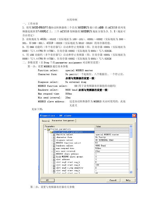
4,用10H功能码(多个寄存器写)启动和停止变频器(即:往寄存器40001(实际地址为0000)写入447FH和447EH)、往寄存器40002(实际地址为0001)写入0202H二、参数设置(在Step 7的parameter assignment对话框里设置)第一步:设置MODBUS通信基本参数Function select: special MODBUS masterCharacter form: No parity(一个起始位、八个数据位、一个停止位,必须与变频器的设置一致)Diagnose select: No external diagMODBUS function select: 03(用于读变频器寄存器值的功能码)Baudrate select: 9600 baud(必须与变频器的设置一致)Max respond time: 500msMin send interval: 20msMODBUS slave address: 这是协议转换器作为MODBUS从站时使用的,此处无意义见如下图:第二步:设置与变频器寄存器有关参数Link MODBUS slave amount:3(协议转换器下实际连接的变频器数量,必须设置,不能多也不能少)Slv1 address:3(第一个变频器的MODBUS地址,必须与变频器的设置一致)Slv1 seg1 start reg_h:0(第一个变频器的第一段读寄存器的起始地址高字节,第一段读寄存器的起始地址是100,高字节为00,低字节为100)Slv1 seg1 start reg_l:100(第一段读寄存器的起始地址低字节)Slv1 seg1 r_reg quantity:2(第一段读寄存器的数量,按字算)Slv1 seg2 start reg_h:1(第一个变频器的第二段读寄存器的起始地址高字节,第二段读寄存器的起始地址是300,即:12CH(十六进制),高字节为01,低字节为44(十进制))Slv1 seg2 start reg_l:44(第二段读寄存器的起始地址低字节)Slv1 seg2 r_reg quantity:2(第二段读寄存器的数量,按字算)Slv1 seg3 start reg_h:20(第一个变频器的第三段读寄存器的起始地址高字节,第三段读寄存器的起始地址是5318,即:14C6H(十六进制),高字节为20(十进制),低字节为198(十进制))Slv1 seg3 start reg_l:198(第三段读寄存器的起始地址低字节)Slv1 seg3 r_reg quantity:2(第三段读寄存器的数量,按字算)Slv1 output length: 10(第一个变频器的输出区长度,按字节算,给每一个变频器分配一个输出区,用于对变频器写操作)Slv2 address:5(第二个变频器的MODBUS地址,必须与变频器的设置一致)Slv2 seg1 start reg_h:0(第二个变频器的第一段读寄存器的起始地址高字节,第一段读寄存器的起始地址是100,高字节为00,低字节为100)Slv2 seg1 start reg_l:100(第一段读寄存器的起始地址低字节)Slv2 seg1 r_reg quantity:2(第一段读寄存器的数量,按字算)Slv2 seg2 start reg_h:1(第二个变频器的第二段读寄存器的起始地址高字节,第二段读寄存器的起始地址是300,即:12CH(十六进制),高字节为01,低字节为44(十进制))Slv2 seg2 start reg_l:44(第二段读寄存器的起始地址低字节)Slv2 seg2 r_reg quantity:2(第二段读寄存器的数量,按字算)Slv2 seg3 start reg_h:20(第二个变频器的第三段读寄存器的起始地址高字节,第三段读寄存器的起始地址是5318,即:14C6H(十六进制),高字节为20(十进制),低字节为198(十进制))Slv2 seg3 start reg_l:198(第三段读寄存器的起始地址低字节)Slv2 seg3 r_reg quantity:2(第三段读寄存器的数量,按字算)Slv2 output length: 10(第二个变频器的输出区长度,按字节算,给每一个变频器分配一个输出区,用于对变频器写操作)Slv3 address:3(第三个变频器的MODBUS地址,必须与变频器的设置一致)Slv3 seg1 start reg_h:0(第三个变频器的第一段读寄存器的起始地址高字节,第一段读寄存器的起始地址是100,高字节为00,低字节为100)Slv3 seg1 start reg_l:100(第一段读寄存器的起始地址低字节)Slv3 seg1 r_reg quantity:2(第一段读寄存器的数量,按字算)Slv3 seg2 start reg_h:1(第三个变频器的第二段读寄存器的起始地址高字节,第二段读寄存器的起始地址是300,即:12CH(十六进制),高字节为01,低字节为44(十进制))Slv3 seg2 start reg_l:44(第二段读寄存器的起始地址低字节)Slv3 seg2 r_reg quantity:2(第二段读寄存器的数量,按字算)Slv3 seg3 start reg_h:20(第三个变频器的第三段读寄存器的起始地址高字节,第三段读寄存器的起始地址是5318,即:14C6H(十六进制),高字节为20(十进制),低字节为198(十进制))Slv3 seg3 start reg_l:198(第三段读寄存器的起始地址低字节)Slv3 seg3 r_reg quantity:2(第三段读寄存器的数量,按字算)Slv3 output length: 10(第三个变频器的输出区长度,按字节算,给每一个变频器分配一个输出区,用于对变频器写操作)见如下图所示:三、计算并分配PROFIBUS的输入输出区(I/Q区)第一步:计算PROFIBUS的输入区(I区)长度第一个变频器(地址为3)所需输入区(I区)长度=(Slv1 seg1 r_reg quantity+ Slv1 seg2 r_reg quantity+ Slv1 seg3 r_reg quantity)*2=(2+2+2)*2=12(字节)第二个变频器(地址为5)所需输入区(I区)长度=(Slv2 seg1 r_reg quantity+ Slv2 seg2 r_reg quantity+ Slv2 seg3 r_reg quantity)*2=(2+2+2)*2=12(字节)第三个变频器(地址为8)所需输入区(I区)长度=(Slv3 seg1 r_reg quantity+ Slv3 seg2 r_reg quantity+ Slv3 seg3 r_reg quantity)*2=(2+2+2)*2=12(字节)三个变频器所需输入区(I区)总长度=第一个变频器所需输入区(I区)长度+第二个变频器所需输入区(I区)长度+第三个变频器所需输入区(I区)长度=12+12+12=36(字节)因此,给协议转换器分配的PROFIBUS输入区(I区)长度应大于或等于36字节第二步:计算PROFIBUS的输出区(Q区)长度三个变频器所需输出区(Q区)总长度= Slv1 output length+Slv2 output length+ Slv3 output length=30(字节)因此,给协议转换器分配的PROFIBUS输出区(Q区)长度应大于或等于30字节第三步:分配PROFIBUS的输入输出区(I/Q区)在Step7的硬件配置里,将模块MOD_DP_V5下面的universal module组件插入slot 1中,然后双击universal module,进入以下界面,设置输出区起始地址(qb0)和长度(30个字节),设置输入区起始地址(ib0)和长度(36个字节)。
Mod-Pro(V2.2)转换器使用说明

Mod-Pro(V2.2)转换器使用说明本模块是PROFIBUS-DP现场总线协议与MODBUS协议之间相互转换的桥。
可以实现PROFIBUS-DP数据与MODBUS数据之间相互转换。
本说明书为Mod-Pro转换器版本V2.2的使用说明。
一、主要用途:将具有MODBUS等专用通信协议接口的设备连接到PROFIBUS总线上,使该设备成为PROFIBUS总线的一个从站。
比如,具有MODBUS接口的变频器、电机启动保护臵、智能高低压电器、流量计、变送器等。
二、性能指标:1,符合PROFIBUS-DP/V0协议(JB/T 10308.3-2001:测量和控制数字数据通信工业控制系统用现场总线第3部分:PROFIBUS规范).2,标准PROFIBUS-DP接口,通信波特率自适应,最大通信波特率6Mbps.3,PROFIBUS 输入/输出(I/O)长度可自由设定,最大输入长度112字节、最大输出长度112字节。
4,透明传输:用户可根据PROFIBUS通信数据区和MODBUS通信数据区的映射关系,实现PROFIBUS总线和MODBUS总线之间的透明通信。
5,MODBUS端通信波特率可选:600bps、1200bps、2400bps、4800bps、19200bps。
6,支持MODBUS协议的01,02,03,04,05,06,07,08,10H功能7,供电:24VDc±5%,90mA.8,通信接口与电源1000VDc隔离.9,外型尺寸(长*宽*高):96mm*84mm*31mm,重量:200克10,工作环境温度:-20~70℃.11,存储温度:-40~85℃.12,工作环境湿度:≤90%.13,防护等级:IP20.三、模块设臵:1、MODBUS通信波特率设臵:在组态软件里,通过选择设备参数(device-specific parameter)设臵MODBUS通信波特率,可设定为:1.2Kbps、2.4Kbps、4.8Kbps、9.6Kbps、19.2Kbps。
- 1、下载文档前请自行甄别文档内容的完整性,平台不提供额外的编辑、内容补充、找答案等附加服务。
- 2、"仅部分预览"的文档,不可在线预览部分如存在完整性等问题,可反馈申请退款(可完整预览的文档不适用该条件!)。
- 3、如文档侵犯您的权益,请联系客服反馈,我们会尽快为您处理(人工客服工作时间:9:00-18:30)。
目录一、性能指标 2二、安装与维护 2三、指示灯说明 3四、模块设臵 3五、PROFIBUS地址设臵 7六、PROFIBUS-DP终端电阻的连接 7七、PROFIBUS-DP从站配臵 8八、报文格式 8九、注意事项 1312本模块是PROFIBUS-DP 现场总线协议与MODBUS 协议之间相互转换的桥。
可以实PROFIBUS-DP 数据与MODBUS 数据之间相互转换。
本说明书为Mod-Pro 转换器版本V4.2的使用说明。
一、性能指标:●符合PROFIBUS-DP/V0协议(JB/T 10308.3-2001:测量和控制数字数据通信工业控制系统用现场总线第3部分:PROFIBUS 规范)。
●标准PROFIBUS-DP 接口,通信波特率自适应,最大通信波特率6Mbps 。
●PROFIBUS 输入/输出(I/O )长度可自由设定,最大输入长度和最大输出长度之和为240字节。
●DP 端具有断线检测功能。
●MODBUS 端提供三种型式与其他MODBUS 设备通信。
通用型MODBUS 主站:与其他MODBUS 从站透明通信,通用性强,可实现多种MODBUS 命令通信。
通用型MODBUS 从站: 与其他MODBUS 主站透明通信,通用性强,可实现多种MODBUS 命令通信。
特殊型MODBUS 主站:给与他相连的所有MODBUS 从站分配固定的I/O 区,用户不必了解MODBUS 协议,只需按说明书操作就可实现通信。
●RS485端通信波特率可选:600bps 、1200bps 、2400bps 、4800bps 、19200bps 、38400bps 。
●供电:24VDc ±5%,90mA 。
●通信接口与电源1000VDc 隔离。
●工作环境温度:-20~70℃。
●存储温度:-40~85℃。
●工作环境湿度:≤90%。
●防护等级:IP20。
二、安装与维护:1、将模块嵌入35MM 标准DIN 槽内(外型尺寸:112 x70 x40 mm ,重量:200g )。
2、接线图: 如图所示,电源端子:电源连接端口24V ——接24V 直流电源正端 0——24V 直流电源地——保护地DP 插座:PROFIBUS-DP 连接端口 脚1——屏蔽地 脚3——接信号B脚5——接信号电源地 脚6——接信号电源正脚8——接信号A3RS485插座:RS485连接端口 脚1——NC,空脚2——A1,接信号A(-)脚3——B1,接信号B(+) 脚4——A1,接信号A(-) 脚5——B1,接信号B(+) 脚6——接屏蔽地3、故障分析⑴、如果电源指示灯不亮,则电源正、负接反了。
⑵、如果PROFIBUS 通信指示灯不亮,说明PROFIBUS 端通信失败,应将通信电缆A 、B 互换。
⑶、如果DP 线检测灯亮,则PROFIBUS-DP 网络连接线短路或断路,应检查PROFIBUS-DP 线路。
⑷、如果本模块与用户设备无法通信,应检查波特率、字符格式等参数设臵是否正确,或将RS485通信电缆A 、B 互换。
三、指示灯说明数据发送灯:MODBUS 端发送数据时,此灯闪亮。
数据接收灯:MODBUS 端接收数据时,此灯闪亮。
DP 线检测灯:当PROFIBUS-DP 网络连接线出现短路或断路时,此灯亮。
DP 通信灯:当PROFIBUS-DP 进入正常通信状态时,此灯亮。
电源灯:模块上电后,此灯亮。
四、模块设臵:1,模块的功能设臵:本模块MODBUS 接口支持三项功能:标准型MODBUS 主站,标准型MODBUS 从站,特殊型MODBUS 主站。
通过选择设备参数(device-specific parameter )的”功能选择”项设置MODBUS 接口功能. 缺省为:标准型MODBUS 主站。
⑴、标准型MODBUS 主站:透明型传输,用户按照MODBUS 协议,将请求桢写入PROFIBUS-DP 主站输出数据区(Q 区)发送到用户设备,校验字节CRC 由本模块自动添加。
从用户设备获得的响应桢送入4PROFIBUS-DP 主站输入数据区(I 区),本模块进行CRC 校验,无误后去掉CRC 字段,将纯用户数据送到主站输入数据区。
支持MODBUS 功能01H ,02H ,03H ,04H ,05H ,06H ,07H ,08H ,0BH,0CH,0FH,10H 。
⑵、标准型MODBUS 从站: 透明型传输。
将接收到MODBUS 主站设备发送过来的请求桢送入PROFIBUS-DP主站输入数据区(I 区),本模块进行CRC 校验,无误后去掉CRC 字段,将纯用户数据送到主站输入数据区。
然后按照MODBUS 协议将响应桢写入PROFIBUS-DP 主站输出数据区(Q 区)发送到MODBUS 主站设备,校验字节CRC 由本模块自动添加。
支持MODBUS 功能01H ,02H ,03H ,04H ,05H ,06H ,07H ,08H ,10H 。
⑶、特殊型MODBUS 主站: 给连接在它下面的MODBUS 从站分配固定的输出区,用于使用10H 功能写参数到相应的从站;给连接在它下面的MODBUS 从站分配固定的输入区,使用03H 功能从从站读取数据送入相应的输入区。
MODBUS 从站的编址必须从1开始连续编址。
2、MODBUS 通信字符格式设臵:在组态软件里,通过选择设备参数(device-specific parameter )设臵通信字符格式,可设定为:⑴、 No Parity:一个起始位、八个数据位,一个停止位。
⑵、 Odd Parity:一个起始位、八个数据位,一个奇效验位、一个停止位。
⑶、 even Parity:一个起始位、八个数据位,一个偶效验位、一个停止位。
缺省为:No Parity ,一个起始位、八个数据位,一个停止位。
此处设定的字符格式与MODBUS 设备设定的必须一致。
3、用户诊断功能的选择:本模块可提供三项用户事件诊断,在组态软件里,通过选择设备参数(device-specific parameter )选择是否激活用户诊断。
选择(NOEXTERNAL DIAG )不激活(即出现用户事件诊断不向主站报警),选择(EXTERNAL DIAG )激活(即出现用户事件诊断向主站报警),用户事件诊断定义:UNIT_DIAG_BIT(0)=" MODE1 ERROR ",MODBUS 模块1通信故障UNIT_DIAG_BIT(1)=" MODE2 ERROR ",MODBUS 模块2通信故障 UNIT_DIAG_BIT(2)=" MODE3 ERROR ",MODBUS 模块3通信故障 UNIT_DIAG_BIT(3)=" MODE4 ERROR ",MODBUS 模块4通信故障 UNIT_DIAG_BIT(4)=" MODE5 ERROR ",MODBUS 模块5通信故障 UNIT_DIAG_BIT(7)=" TONGXUN ERROR ",标准MODBUS 主站通信故障 缺省为不激活4、MODBUS通信波特率设臵:在组态软件里,通过选择设备参数(device-specific parameter)设臵MODBUS通信波特率,可设定为:300bps、600bps、1.2Kbps、2.4Kbps、4.8Kbps、9.6Kbps、19.2Kbps,38.4Kbps,56Kbps,57.6Kbps,115.2Kbps。
缺省为:9.6Kbps。
此处设定的通信波特率与MODBUS设备设定的必须一致。
5,最大应答时间选择:最大应答时间是指请求桢发送完成后,等待响应桢的最长时间。
在组态软件里,通过选择设备参数(device-specific parameter)设臵最大应答时间,缺省为:500ms、6,最小发送间隔:最小发送间隔是指发送两个请求桢之间最短的时间。
在组态软件里,通过选择设备参数(device-specific parameter)设臵最小发送间隔,缺省为:20ms、7,MODBUS从站地址(仅作为MODBUS从站时设臵):当本模块MODBUS接口设臵为标准型MODBUS从站时,需设臵MODBUS从站地址。
在组态软件里,通过选择设备参数(device-specific parameter)设臵MODBUS从站地址。
568,连接模块数量(仅MODBUS 特殊主站时设臵):当本模块MODBUS 接口设臵为特殊型MODBUS 主站时,需设臵连接MODBUS 从站数量,且与之相连的MODBUS 从站的地址范围从1开始,连续编址。
在组态软件里,通过选择设备参数(device-specific parameter)设臵MODBUS 从站数量。
9,模块1读起始高(仅MODBUS 特殊主站时设臵):当本模块MODBUS 接口设臵为特殊型MODBUS 主站时,设臵与之相连的MODBUS 从站1的读起始寄存器地址高字节。
在组态软件里,通过选择设备参数(device-specific parameter )设臵模块1读起始高。
10,模块1读起始低(仅MODBUS 特殊主站时设臵):当本模块MODBUS 接口设臵为特殊型MODBUS 主站时,设臵与之相连的MODBUS 从站1的读起始寄存器地址低字节。
在组态软件里,通过选择设备参数(device-specific parameter )设臵模块1读起始低711,模块1读数量(仅MODBUS 特殊主站时设臵,以字为单位):当本模块MODBUS 接口设臵为特殊型MODBUS 主站时,设臵与之相连的MODBUS 从站1的连续读取寄存器个数。
在组态软件里,通过选择设备参数(device-specific parameter )设臵模块1读数量12,模块1输出长度(仅MODBUS 特殊主站时设臵,以字节为单位):当本模块MODBUS 接口设臵为特殊型MODBUS 主站时,设臵与之相连的MODBUS 从站1的输出数据区长度。
在组态软件里,通过选择设备参数(device-specific parameter )设臵模块1的输出数据区长度五、PROFIBUS 站地址设臵:右边中间的两个圆型旋钮拨码开关用于设臵PROFIBUS 从地址,左边旋钮拨码设臵地址的十位(X10), 右边旋钮拨码设臵地址的个位(X1),地址范围0~99.缺省为7.六、PROFIBUS-DP 终端电阻的连接:A 型和B 型总线电缆的两端应该分别使用Rt A 和Rt B 来端接。
在EIA RS-485中规定的端接电阻Rt 是以下拉电阻Rd (与数据地DGND 连接)和上拉电阻Ru (与正电压VP 连接)做补充。