e1以太网协议转换器
协议转换器故障分析及处理方法:

协议转换器故障分析及处理方法:接口简介:我们常用的接口有E1接口(又叫G.703接口)、以太网接口、V.35接口。
(1)E1端口特性如下:E1接口标准:E1接口符合G.703标准接口码速: 2.048Mbit/s±50ppm码型:HDB3码阻抗:75Ω(非平衡)、120Ω(平衡)连接器:BNC(75Ω不平衡)/ RJ45(120Ω平衡)抖动特性:满足G.742和G.823标准(2)以太网端口特性速率:10M或100M,全双工,半双工完全自适应协议: 支持IEEE 802.3,IEEE 802.1Q(VLAN)MAC地址表:可以学习1024个MAC地址以太网总缓存:64MBits SDRAM物理接口:RJ45接口,支持交叉/直通线自适应(3)V.35接口特性速率: 2.048Mbps接口特性:满足V.35标准连接器:DB25孔座连接方式:DCE时钟方式:G.703恢复时钟、内时钟以下介绍各种设备的具体使用说明:一、E1转以太网非成帧协议转换器E1-10/100BT 接口转换器提供ITU-T G.703标准E1接口与10/100Base-T以太网接口转换,10/100Base-T通道将其传送到交换机、HUB、路由器、网桥或其他设备上。
并能通过光端机等传输设备进行传输,联网后两个局域网就成为一个局域网里的两个网段。
前面板分布台式接口转换器前面板图指示灯介绍:设备前面板共有7个指示灯,对应的指示灯指示本地设备工作状态,从左到右面分别为名称颜色状态描述闪烁表示E1口有数据收发DATA 绿色亮/灭表示E1口没有数据接收和发送亮/闪以太网连接上/有数据收发LNK 绿色灭以太网没有连接上亮E1线路信号丢失LOS 红色灭E1线路信号正常亮此设备为不成帧E1,无效LOF 红色灭此设备为不成帧E1,无效亮设备处于测试状态(ANA,DIG,REM,PATT有任一接下时) TEST 黄色灭设备处于正常工作状态PTOK绿色亮PATT 按钮按下时,伪随机码检测正常 灭 PATT 按钮按下时,伪随机码检测不通 闪烁 PATT 按钮按下时,伪随机码检测有误码 PWR 绿色亮电源已接上 灭电源没有接上后面板分布(台式)后面板图(AC 220V )后面板图(DC -48V )E1 接口(台式)本设备E1接口提供自适应的75Ω和120Ω两种阻抗,不用设置。
Orion VCL-4 以太网1E1到E1接口转换器用户手册说明书

VCL-4 Ethernet over 1E14*10/(100) Base-T to E1 Interface ConverterData Sheet & User ManualORION TELECOM NETWORKS INC.RIONTELECOMNETWORKSHeadquarters: Phoenix, Arizona Orion Telecom Networks Inc.20100, N 51st Ave, Suite B240,Glendale AZ 85308Phone: +1 480-816-8672Fax: +1 480-816-0115E-mail:**********************Website: Regional Office: Miami, Florida Orion Telecom Networks Inc.4000 Ponce de Leon Blvd. Suite 470,Coral Gables, FL 33146 U.S.A.Phone: 1-305-777-0419, Fax: 1-305-777-0201E-mail:**********************Website: WarrantyThis Orion product is warranted against defects in material and workmanship for a period of one year from the date of shipment. During the warranty period, Orion will, at its discretion, either repair or replace products, which prove to be defective. For warranty service or repair, this product must be returned to a service facility designated by Orion. The buyer shall prepay shipping charges to Orion and the company shall pay shipping charges to return the product to the buyer. However, the buyer shall pay all the shipping charges, duties and taxes for products returned to Orion from another country.Limitation of WarrantyThe foregoing warranty shall not apply to defects resulting from improper or inadequate maintenance by the buyer, the buyer-supplied firmware or interfacing, unauthorized modification or misuse, operation outside of the environmental specifications for the product or improper site preparation or maintenance.Exclusive RemediesThe remedies provided herein are the buyer's sole and exclusive remedies. Orion shall not be liable for any direct, indirect, special, incidental or consequent damages, whether based on contract or any legal theory.NoticeThis manual contains information that is proprietary to Orion T elecom Networks Inc. No part of this publication may be reproduced in any form whatsoever without prior written approval by Orion T elecom Networks Inc.Safety WarningsThe exclamation point within a triangle is intended to warn the operator or service personnel of operation and maintenance factors relating to the product and its operating environment, which could pose a safety hazard.Always observe standard safety precautions during installation, operation and maintenance of this product. Only qualified and authorized service personnel should carry out adjustment, maintenance or repairs to this instrument. No adjustment, maintenance or repairs should be performed by either theoperator or the user.!INDEXThe VCL-4 Ethernet over 1E1 Converter provides the user a facility to transport Ethernet (multiple LANs) over an E1 link. The equipment converts and transports upto 4 x Ethernet links over an E1 in a shared* mode, or a discrete** mode, depending on the user's preference and selection.*In shared mode: All 4 Ethernet channels are transported over the same shared E1 link and areallowed full access to each other's path. The usermay select this mode if the user desires that all of the 4 x Ethernet links that are being transported over the same E1 to optimally share its bandwidth resources and where discretion is essential.*In discrete mode: All 4 Ethernet channels are transported over the same E1 link, but without allowing intrusion or access to each other's path. The user may select the discrete* mode when the user desires to transport all 4 Ethernet channels over the same E1 line discretely, and without allowing access to each other.The equipment shall always be installed and used in pairs, with one terminal being installed at either end (each side) of the network.The VCL-4 Ethernet over 1E1, 4*10(100)Base-T to E1 Interface Converter is an ethernet extension device utilizing TDM telecom infrastructure (the telecom network of E1s, or of PDH, SDH and E1/E3/SDH microwave etc. carrying E1s).The VCL-4 Ethernet over 1E1, 4*10(100)Base-T to E1 Interface Converter converts the Ethernet Data into E1 frame format for transmission over the existing TDM (E1) links and then re-converts the E1s back into Ethernet Data at the far-end terminal. It function is to primarily provide a BRIDGE between two Ethernet LANs over the existing E1 based telecom network. The device can effectively utilize the redundant bandwidth of telecom operators' existing TDM network to transport Ethernet data with low investment.*Optional powers 220V AC and -48V DC. May be ordered with either power option.DescriptionApplicationsThis equipment may be used for the following purposes:1.Bridging Ethernet LANs over existing TDM (E1) telecom network. Extending Ethernet Networks utilizing TDM (E1) landline based telecom infrastructure.2.Using telecom network of E1s / PDH / SDH Microwave etc. carrying E1s to transport Ethernet Data.In all these cases the equipment be always installed and used in pairs, with one terminal beinginstalled at either end (each side) of the network.VCL-4 Ethernet over 1E1VCL-4 Ethernet over 1E1Description and ApplicationsShared link modeIn the "shared link mode", each LAN can view and talk to other LANs. Example: each LAN can view and talk to all other LANs at same site or the corresponding remote side. This mode may be selected for use if bandwidth optimization and usage is of prime importance and the user is not averse to sharing the E1 link resources with the other LANs being transported on the same E1 link.For example all four Ethernet Ports at local site are in LAN Mode and will also communicate to all four Ethernet Ports at far end site.T ypical ApplicationNote:In the "shared link mode", the VLAN switch must be OFF (The ethernet ports are notisolated to each other on both sides of the E1 link).Note: Each DIP Switch is ON in downside and OFF in upside.POWERConverter in V LAN Mode “shared link mode”E1NetworkE1Network E1E1VCL-4 Ethernet over E1VCL-4 Ethernet over E1VCL-4 Ethernet over 1E1T ypical ApplicationPOWERDiscrete link modeIn the "discrete link mode" each LAN is bridged to, and can only talk to its corresponding LAN on the remote side. It can not talk to any other LAN either at same side or the remote side. This mode may be selected for use if the users do not wish to share the E1 link resources with the other LANs being transported on the same E1 link.For example the Ethernet Port 1 (at local site) will communicate to Ethernet Port 1 at far end site and so on for Port 2 etc.Example: In the discrete link mode , the LAN 1 (Ethernet Port 1 of the equipment) only can talk to the corresponding LAN 1 (Ethernet Port 1 of the equipment) at remote side and can not talk to any other LAN, either on remote side or same side.Note: In the discrete link mode , the VLAN switch must be ON (Ethernet Ports isolated) in Boththe units.Note: Each DIP Switch is ON in downside and OFF in Upside.Converter in “discrete link mode”E1NetworkE1Network E1E1VCL-4 Ethernet over E1VCL-4 Ethernet over E1VCL-4 Ethernet over 1E1Discrete Link ModeVCL-4 Ethernet over 1E1Technical features T echnical Features1.The maximum transmission rate of 4 Ethernet data over E1 links is2.048 Mbit/s2.Supporting 1600 long frames, accordance with Interior Switching Link (ISL) Protocol3Supporting local E1 port loop-back4.The Ethernet Port is self-adaptive to crossover or Straight/Parallel cable to avoid the trouble of re-wiring5.Supports up to four Ethernet Ports. Supports port mask6.Ethernet auto negotiation function. Supports 10M/100M and working modes of bothfull-duplex and semi-duplex7.T ransparently transmits ultra-long frames stipulated in IEEE 802.1Q, and supports Ethernetswitches with VLAN function8.Imbedded, dynamic Ethernet MAC address list (1024 addresses), and filter function forlocal data frames9.Can support multiple LANs of different network addresses10.Optional powers 220V AC and -48V DC. May be ordered with either power option.E1 Port SpecificationsNumber of E1 Ports`OneLine Rate E1 (2.048 Mbps ± 50 bps)Framing Framed / Un-Framed / Multi-FramedElectrical As per ITU-T G.703Jitter As per ITU-T G.823Impedance 120 Ohm (RJ-45)Impedance75 Ohm (BNC)Ethernet Port SpecificationsNumber of Ports FourPort T ypes10/100BaseT (Auto-negotiating)Standards Compliance IEEE 802.3Data Rate10/100BaseT transmission rate limitedto 2.048Mbps (maximum)Connectors RJ-45 (10/100 BaseT Electrical)VCL-4 Ethernet over 1E1Installation and Commissioning Installation and Commissioning1. Qualifying the network!The time-slots should be configured according to the planning of E1 link. If the accessed E1 link is being exclusively and only by this equipment (i.e. VCL-4 Ethernet over E1, 4*10(100)Base -T to E1 Interface Converter), it should be configured as transparent transmission to increase Ethernet service bandwidth*** Note: Due care must be taken to ensure that the settings meet the user requirements of “shared line" or "discrete line" service!The remote time-slots shall be configured in accordance with the local time-slots. The configuration of the equipment on both sides should be the same!The length of the Ethernet cable shall not exceed 100m2.Grounding!When the equipment is used with the AC~220V power supply, the 3-core socket must be grounded for protection!The other equipment (e.g. optical terminal) connected with this equipment must also be grounded to earth for protection3.InstallationStep 1 Power up the Ethernet over E1 (IPoTDM) equipment.Important: Please ensure that Ethernet over E1 (IPoTDM) equipment is powered-up prior to connecting the ethernet and the E1 links.Step 2 Connect E1 line after ensuring that transmission device, port converter and ethernet switch have been grounded.A Bit Error Rate (BER) test may be conducted on E1 link using a BERT tester to ensure that the E1 errors are within the permitted limits / threshold.Step 3 Please configure the Ethernet Mode of the Ethernet over E1 (IPoTDM) equipment at both sides as well as the Ethernet Ports of the devices that are connected to the Ethernet over E1 (IPoTDM) equipment. Connect the ethernet links.The equipment is used to bridge Multiple LANs. Please ensure that the connecting LANs on both sides of the link are operating in the same IP domain.Step 4 Ping over the ethernet connection from one side to the other (near-end to the far-end) to verify the link.Important Note: Please power-up the equipment prior to connecting the ethernet and the E1 links.VCL-4 Ethernet over 1E1Front Panel Description of the Front Panel1.Front PanelOutline of the front panel is as follows:POWERPower LED: The GREEN LED indicator lights of power supply is lit under normal working condition when the power supply is connected.VCL-4 Ethernet over 1E1Definition of Indications Definition of IndicatorsStatus of Ethernet Port LEDsIndicator light Port 1Port 2Port 3Port 4Link LED GREEN Input Signal Input Signal Input Signal Input Signal "ON" (Solid)Detected Detected Detected DetectedLink LED GREEN Receiving/ Receiving/ Receiving/Receiving/ "ON" (Flashing)Sending Data Sending Data Sending Data Sending Data10/100M "Green" Port under Port under Port under Port under100M service 100M service 100M service 100M servicemode mode mode mode10/100M "OFF” Port under Port under Port under Port under10M service 10M service 10M service 10M servicemode mode mode modeDup/Col "ON" Port under Port under Port under Port under (Solid)full-duplex full-duplex full-duplex full-duplexmode mode mode modeDup/Col "OFF" Port under Port under Port under Port under (Solid)semi-duplex semi-duplex semi-duplex semi-duplexmode mode mode modeDup/Col "OFF" Ethernet Port Ethernet Port Ethernet Port Ethernet Port (Flashing)has detected has detected has detected has detectedany conflict any conflict any conflict any conflicterror error error errorStatus ofIndicator light E1 Circuit LED Alarm and statusE1 LOS RED "ON"E1 port is unconnected or bad connectedE1 LOS RED "OFF"E1 port is connected properlyAIS YELLOW "ON"1's code alarm of E1 lineAIS YELLOW "OFF"OKDIP switch settings on front panel are as followsSwitch Description Default 1 (CLK)ON Internal clock: The system is running on its internal clock ONOFF Line clock: The system is drawing clock from E1 line.2 (RLOOP)ON No loop-back on E1 interface.ONOFF E1 Interface is loop-back.3 (AUTO)ON Ethernet Port is running in self-adaptive mode.ONOFF Ethernet Port rate is depend on SPD4 (SPD)ON Ethernet Port rate is 100M if "AUTO" is off ONOFF Ethernet Port rate is 10M if "AUTO" is off5 (DPX)ON Ethernet Port is running in full-duplex mode ONOFF Ethernet Port is running in semi-duplex mode6 and 7Speed Limit configuration of Ethernet Interface(SPLD 1 and SPLD 1SPLD 2 Port Speed limit ON SPLD 2)ON ON None port is speed limitON OFF 1 and 2 port speed, limit 512 K; 3 and 4 port, noSpeed limitOFF ON 1 port speed limit, 1M; 2,3 and 4, no speed limit.OFF OFF Speed limit, 512 K for all ports8 (VLAN)ON Ethernet Port isolated (discrete link mode)OffOFF Ethernet Port is not isolated (Share link mode)Note: Each DIP Switch is ON in downside and OFF in Upside.Power supply switch: T o switch the power OFF/ON.2.(A) Back Panel - AC InputThe back panel of 4Ethernet over E1 (IPoTDM) equipment is as follows with AC Input:(B) Backpanel - DC InputThe back panel of 4Ethernet over E1 (IPoTDM) equipment is as follows with -48V DC Input:DIP switch settings on Back panel!E1 socket for 120 Ohms balanced: All DIP switches MUST be OFF (upside)!E1 socket for 75 Ohms unbalanced: All DIP switches MUST be ON (downside)AC220V: represents the unit uses AC~220V power supply.*Optional powers 220V AC and -48V DC. May be ordered with either power option.E1 RJ-45 Pinouts Details120W RJ45 pin-outPIN No.Definition of function Signal Direction 1NC2 TX+ (transmitted data +)E1 Data Output3TX- (transmitted data -)E1 Data Output4NC5NC6RX+ (received data +)E1 Data Input7RX- (received data -)E1 Data Input8NCEthernet RJ-45 PinoutsEthernet RJ-45 PinoutsPIN No.Definition of function Signal Direction 1TX+ (transmitted data +)Data Output2TX- (transmitted data -)Data Output3RX+ (received data +)Data Input4NC5NC6RX- (received data -)Data Input7NC8NCTime-slot configuration of E1 port: For E1 time-slot configuration, the DIP Switch settings on the bottom panel are as follows:The time-slot DIP switches located at the bottom of the equipment marked with TS0~TS31 bits corresponding to 0~31 time-slots of E1 channel.Note: It is recommended to set the TS0 DIP switch OFF .3. Bottom PanelThe Bottom panel of 4Ethernet over E1 (IPoTDM) equipment is as follows:Working Mode Switch SettingUnframedAll switches are set to OFFFramed (CCS/PCM-31)S0 set to OFF , and the occupied time slots to ON Multi-Framed (CAS/PCM-30 )All switches S0~S31 set to ON but S16 is set to OFFExample 1: If you wish to use only first 5 time-slots then you need to set the S0 time-slots to OFF and switch S1 to S5 to ON and time-slot S16 will be set to ON.Example 2: If you wish to carry first 8 time-slots on 512Kbps, then you need to set the S0 time-slot OFF and switch S1 to S8 to ON (i.e. since each time-slot consumes 64Kbps, so 8 time-slots will consume 8 x 64Kbps = 512Kbps) and time-slot S16 will be set to ON.Example 3: If you wish to carry 20 time-slots on 1.28Mbps (64Kbps x 20) then you need to set time slot S0 OFF and S1 to S21 time-slots to ON. Please remember that the time-slot S16 will be used as signaling time-slot.VCL-4 Ethernet over 1E1Bottom PanelVCL-4 Ethernet over 1E1Installation Instructions and Trouble-Shooting Installation Instructions and T rouble-shootingA Installation Instruction1.Perform the following tests prior to usage:Inspect every configuration switch on the panels to see whether they are set in normalworking state, i.e. PWR and E1 LOS light ON; in the case of framed E1, E1SYL shall be ON,other lights OFF.2.Arrange E1 line impedance and time-slots as required, plug in E1 input/output lines andEthernet line, then turn ON the power supply, the equipment comes into normal workingconditions.3.One equipment MUST be set to master clock and other MUST be set to line clock(loop-timed).B T rouble-shootingWhen the equipment is under normal working conditions, the three indication lights, E1LOS E1SYL and AIS, shall be OFF.1.T rouble: E1LOS light ONCheck point: make E1 loop-back at E1 input port and output port, if the light OFF, thenhighlight the check on E1 input line. Please check with the E1 Cable.2T rouble: E1SYL light ONCheck point: Make E1 loop-back at E1 input port and output port, if the light OFF, thenhighlight the check on the opposite-end interface converter to see whether set to framingservice mode. If the opposite side interface converter has been set to framing service mode,check the transmission path of E1 for any disconnect. The alarm is valid if port is working on framing mode.3.T rouble: AIS light ONCheck point: normally this fault is due to either of the following reasons:1. The opposite-end E1 equipment cuts off receiving.2. There are other devices working under test on E1 transmission line.3. E1 Channel is in loop-back state.VCL-4 Ethernet over 1E1General Parameters 4.T rouble: LINK light OFFCheck point: This fault is basically due to the error in making network (crossover orstraight-through) cable. Please check if the equipment I require crossover cable or straight-through cable you are connecting to. VCL-4 Ethernet over E1 is self-adaptive to crossover or straight-through cable.5.T rouble: LINK light in normal state, but data PING failsCheck point:1. Check whether the state of the equipment Ethernet is in accordance with thatof the opposite-end Ethernet; If not then, cancel the self-adaptive state ofEthernet Interface and change compulsorily to configure speed and duplexso as to be in accordance with the other end.2. Check whether the equipment E1 port or E1 transmission channel is underloop-back or other test conditions, if any, then cancel it.3. Check whether the time slot configuration of the local equipment is inaccordance with the remote one. If not then, configure it to be in accordance.6.T rouble: Data succeed in PING, but with frame lossCheck point: This fault may be due to the following reasons:1. Incompatible configuration of E1 port impedance.2. Incomplete physical connection of E1 port, e.g. only one pole connected atreceiving end.3. Wrong configuration of clock, change the clock to master clock.7.T rouble: The communication is normal prior to configure port mask, but blocked after portmask configuration.Check point: Ensure whether the remote equipment also configured port mask, whether the port mask configuration at two ends is in accordance; after port mask configuration, onlyEthernet of same port number can perform communications. Check whether VLAN switch set to OFF (shared link mode is ON) the equipment connected to Ethernet interface, if any, T oggle the VLAN switch to ON (set the equipment for discrete link mode).General1.Power SupplyAC Mains Input : 220V 20% (AC Mains input model).*Optional powers 220V AC and -48V DC. May be ordered with either power option.Power Consumption: <10W2.Service Conditions00Working temperature: -5C ~ +50C00Storage temperature: -20C ~ +70CRelative humidity: 5 % ~ 95% (at 35C)Do not subject the equipment to corrosive solvents, gas, dust or intense magnetic-fieldinterference.3.Dimensions : 200mm x 150mm x 40mm4.Weight : 0.86 Kg.Note:1 The equipment shall always be installed and used in pairs, with one terminal beinginstalled at either end (each side) of the network.2Operation and maintenance of network equipment require professional knowledge and experience. We recommend the equipment to be managed only by qualified technicians.Should you require technical assistance please consult the provider, or contact ourSUPPORT DESK at ************************T echnical specifications are subject to changes without notice.Windows is the registered T rademark of Microsoft Corporation, USA.Revision 06 - November 30, 2012.VCL-4 Ethernet over 1E1SupportHeadquarters: Phoenix, Arizona Orion Telecom Networks Inc. 20100, N 51st Ave, Suite B240, Glendale AZ 85308Phone: +1 480-816-8672Fax: +1 480-816-0115E-mail:********************** Website: Regional Office: Miami, Florida Orion Telecom Networks Inc.4000 Ponce de Leon Blvd. Suite 470, Coral Gables, FL 33146 U.S.A. Phone: 1-305-777-0419,Fax: 1-305-777-0201E-mail:********************** Website: 。
e1转以太网协议转换器

e1转以太网协议转换器e1转以太网协议转换器是一种用于将E1接口信号转换为以太网接口信号的设备,它在不同网络之间起着重要的桥梁作用。
本文将介绍e1转以太网协议转换器的工作原理、应用场景以及选购注意事项。
e1转以太网协议转换器的工作原理是通过将E1接口信号转换为以太网接口信号,实现不同网络之间的互联互通。
在传统的通信网络中,E1接口被广泛应用于传输语音和数据,而以太网接口则是现代网络的主流接口标准。
e1转以太网协议转换器的出现,使得传统的E1接口设备能够与现代的以太网设备实现互联,为网络的升级和演进提供了便利。
e1转以太网协议转换器在实际应用中具有广泛的场景,其中包括但不限于以下几个方面:1. 电信运营商网络,在电信运营商的网络中,由于历史原因和技术遗留问题,E1接口设备和以太网设备并存。
而e1转以太网协议转换器可以很好地实现这两种不同接口设备之间的互联互通,为电信运营商网络的升级和优化提供了技术支持。
2. 企业网络,许多企业内部的通信设备仍然采用E1接口,而随着企业网络的发展和扩张,需要与以太网设备进行互联。
e1转以太网协议转换器可以满足企业网络中不同接口设备之间的互联需求,为企业的通信和数据传输提供了便利。
3. 校园网络,在学校和教育机构的网络中,也存在着E1接口设备和以太网设备并存的情况。
e1转以太网协议转换器可以帮助学校实现不同接口设备之间的互联,为校园网络的建设和管理提供了技术支持。
在选购e1转以太网协议转换器时,需要注意以下几个方面:1. 技术标准,要选择符合国家标准和行业标准的产品,确保设备的性能和稳定性。
2. 兼容性,要考虑设备的兼容性,确保能够与已有的通信设备和网络设备实现良好的互联互通。
3. 性能参数,要关注设备的性能参数,包括传输速率、时延、误码率等,确保设备能够满足实际应用的需求。
4. 品牌信誉,要选择有一定品牌影响力和良好口碑的厂家生产的产品,确保设备的质量和售后服务。
综上所述,e1转以太网协议转换器在不同网络之间起着重要的连接作用,具有广泛的应用场景。
以太网至多路E1协议转换器
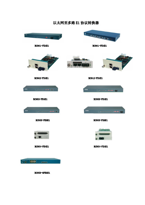
以太网至多路E1协议转换器RC901-FX4E1 RC901-FE4E1 RC902-FX4E1 RC912-FX4E1RC953-FE4E1 RC953-FX4E1 RC953-FE8E1 RC953-FX8E1 RC954-FE4E1 RC954-FX4E1 RC953-8FE8E1RC902-FE4E1 RC954-2FE8E1-BL RC954-2FE4E1-BLRC954-FE8E1产品简述:该系列产品是具有反向复用功能的协议转换器,可以充分利用运营商多路E1线路来同时传递1路以太网业务,传输带宽最大支持16M。
根据用户的需求不同,可以通过调整E1的接入数量来灵活的调整用户的带宽。
分为第一代和第二代两代产品,其中第二代产品采用了公司自主研发EoPDH芯片,在第一代产品的基础上增加了全程网管、链路容错功能。
应用方案:RC954-FE4E1与RC953-FE4E1配合可以为用户的两个远程局域网间提供2M~8M的业务通道。
并且通过RC NView网管平台可以对局端、远端设备实施监管。
功能特点:第一代➢灵活的带宽选择:可以任意指定绑定E1的数量,即链路的带宽可任意调整;➢提供完备的告警指示和本/远端E1线路环回功能,方便开通与故障维护;➢可抵御512UI漂移,具有良好的抗抖动和抗漂移能力;➢具有E1线路故障转移功能,可将E1接收、发送侧告警转移到以太网接口;➢内建超大缓存,缓解数据突发冲击;➢配合NView NNM综合网管平台可实现局端、远端设备的网管;第二代新增功能➢良好的线路容错能力:当使用多路E1时,各路E1成员差分延迟为+/-16ms,可保证在各种复杂网络下可靠稳定的运行。
当某路E1线路性能劣化,可自动将该链路排除在外,允许在降低总体传输容量的同时保证业务正常传送,待故障链路性能正常后,会自动恢复该链路的使用;➢网管能力:支持局端、远端协议转换器的网管,光口设备支持对末端收发器的管理;技术参数:。
瑞斯康达RC953

RC953-FX4E1、RC953-FX8E1、RC954-FX4E1具有反向复用功能的E1协议转换器产品简介:RC953-FX4E1、RC953-FX8E1、RC954-FX4E1是北京瑞斯康达科技发展有限公司自主研发的具有反向复用功能的E1协议转换器。
具有1路用户以太网光口和多路E1接口(4路或8路)。
主要用于接入或传送带宽大于2Mbps、小于16Mbps的以太网业务。
即可以成对使用完成用户点到点组网需求,也可做为远端设备,配合收发器、RC953-8FE16E1、RC953-GESTM1完成用户点到多点的组网需求。
产品特点:✧灵活的组网方式可以按需灵活实现点到点及点到多点的组网。
✧灵活的带宽选择可以任意指定绑定E1的数量,即链路的带宽。
设备间E1接口无需一一对应,可自动识别进行建链。
✧强大的线路容错能力可以任意指定每个E1内所占用的时隙,以灵活的实现用户的业务需求。
当一路或多路E1出现误码,在误码门限值内,可保证业务的正常传送;当误码大于门限值,可自动将故障链路排除在外,允许在降低总体传输容量的同时保证业务正常传送。
产品属性:以太网接口:✧提供1个FE接口。
✧支持自动协商,AUTO-MIDX,10M/100M,全/半双工,支持全双工模式下的802.3x和半双工模式下的背压流控。
✧以太网数据采用HDLC帧格式封装。
E1接口:✧提供4或8路E1接口。
✧通过拨码可任意设定E1可用数量。
✧支持E1链路线序的自动识别。
✧E1虚级联组成员差分延时+/-16ms。
✧支持E1虚级联组内链路的自动建链、拆链。
✧E1端口仅支持成帧模式,默认采用FAS+CRC4的PCM31格式。
✧E1接口类型:75Ω非平衡、120Ω平衡接口可选。
✧比特率:2048Kbps±50ppm。
✧码型:HDB3。
管理功能:✧支持全面的网管功能。
✧支持远端集中监控。
✧支持E1环回测试和误码仪功能。
✧面板支持丰富的E1线路信息指示。
双协议转换器E1转LAN&V.35应用说明

GVE-TG.703/LAN网桥转换器GVE-TplusG.703/V.35/LAN三合一复用器用户手册目录第一章概述1.1前言1.2技术指标第二章安装和使用2.1电源和环境要求2.2前后面板2.3串行接口信号线2.4内部开关设置第三章技术支持第一章概述1.1前言GVE-T是采用ASIC电路设计技术研制的利用1条E1线路传输以太网Ethernet 数据的G.703到以太网桥转换器。
以扩展以太网的传输距离和应用范围。
它配有E1/G.703作为线路接口, G.703可以是成帧N×64Kbps(N=1--31)和无帧2048Kbps,俗称信道化和非信道化,在成帧模式下支持CRC4 ON和OFF,CAS/CCS(30和31时隙)的选择。
传输时钟可以从接收信号G.703线路中复原,也可以是内时钟工作方式。
GVE-T的以太网Ethernet UTP口具备VLAN 802.1 Q功能。
GVE-T满足ITU的G.703、G.704和G.706的要求。
GVE-T具有数据和图象传输的两种模式可供选择。
GVE-T具有本地和远程环路,可以方便用户进行线路测试和故障诊断,以实现端对端的完整性测试。
GVE-T前面板有丰富的指示灯, 显示设备的工作状态及告警信号。
GVE-Tplus是GVE-T的升级产品,是采用ASIC电路设计的最新研制成功的,集多种类型机器于一身的,一种多功能,多用途E1/ G.703到V.35和局域网LAN 口的三合一复用器,也可称为三合一接口转换器。
GVE-Tplus能将E1同时转换成V.35口和局域网LAN口,每个端口的带宽都能设成N×64Kbps(N=1--31)连续的数据流,但两个端口带宽相加必须≤31。
并把它插入到E1的PCM时隙里。
支持CRC4 ON和OFF,CAS/CCS(30和31时隙)的选择。
每个端口速率的分配都有一个独立的五位开关来完成。
GVE-Tplus不仅能设置成GVE-T,而且能把E1全部分配给数据端口V.35,但E1必须是成帧的N×64Kbps(N=1--31),工作方式可以是内时钟和从时钟,也可以是N×64Kbps(N=1--31)外时钟方式,实现尾接电路。
e1协议转换器

e1协议转换器E1协议转换器是一种广泛使用的通信设备,用于将E1协议信号转换成其他协议的信号。
E1协议是一种数字通信协议,主要用于传输语音和数据信号。
这种转换器的作用是将E1信号转化成其他协议,以实现不同通信设备之间的互联。
E1协议转换器通常具有两个E1接口和多个其他协议接口,如Ethernet、RS232、V.35等。
通过连接到E1接口,它可以接收和发送E1信号,并将其转换成其他协议的信号。
这些转换器还具有信号调整、时钟同步和误码监测等功能,以保证信号的稳定和可靠传输。
使用E1协议转换器可以实现不同地区、不同厂商和不同类型的通信设备之间的互联。
例如,将E1协议转换成Ethernet信号可以实现电信宽带接入,将E1协议转换成RS232信号可以实现串口通信,将E1协议转换成V.35信号可以实现数据传输等等。
这些转换器在现代通信网络中扮演着重要的角色。
E1协议转换器具有多种应用场景。
在企业内部通信中,它可以用于连接不同办公点的通信设备,实现语音和数据的传输。
在电信运营商的网络中,它可以用于连接不同地区的交换机,实现用户通信的互联。
在工业自动化系统中,它可以用于连接不同设备的传感器和控制器,实现数据的采集和控制。
E1协议转换器的优点在于其高可靠性和稳定性。
它采用了先进的数字信号处理技术和误码纠正技术,能够保证信号的传输质量。
同时,它还具有自动切换和备份功能,可以在主链路发生故障时自动切换到备份链路,保证通信的持续性和可靠性。
此外,E1协议转换器还具有灵活的配置和管理功能。
通过管理软件,用户可以对转换器进行配置和监控,包括信号调整、时钟同步、误码监测等。
用户还可以根据需要设置路由表和策略,实现灵活的网络管理。
总之,E1协议转换器在现代通信网络中起着重要的作用。
它能够实现不同协议之间的互联,提高通信设备的灵活性和可用性。
随着通信技术的不断发展和需求的不断增长,E1协议转换器将在更多的领域得到应用,为通信网络的建设和发展做出贡献。
E1网桥协议转换器使用说明

1/2/4E1-10/100M 系列协议转换器用户手册安全使用须知协议转换器在设计使用范围内具有良好可靠的性能,但仍应避免人为对设备造成的损害或破坏。
◆仔细阅读本手册,并保存好本手册,以备将来参考用;◆不要将设备放置在接近水源或潮湿的地方;◆不要在电源电缆上放任何东西,不要将电缆打结或包住,并应将其放在不易碰到的地方;◆电源接头以及其它设备连接件应互相连接牢固,请经常检查;◆连接电源线时,务必认真按接线柱标注接线;所用电源必须满足如下条件:1.直流-48V机种:-36V ~-72V2.直流+24V机种:+24 V±15%3.直流-24V机种:-24 V±15%4.交流220V机种:220V±20%,50Hz◆请注意设备清洁,必要时可用软棉布擦拭;◆不要堵塞通风口;◆在下列情况下,请立即断开电源,并与公司联系:1.设备进水;2.设备摔坏或机壳破裂;3.设备工作异常或展示的性能已完全改变;4.设备产生气味、烟雾或噪音。
◆请不要自己修理设备,除手册中有明确指示外。
一、概述n*E1-10/100M系列产品是北京佳特科为科技发展有限公司()使用自主开发的专用集成电路研制生产的反向复用设备,将以太数据包复用在n路E1中传输,可以非常方便地利用公众网中现有的丰富的E1资源快速组建宽带以太数据网。
该产品对E1通道无任何特殊要求,并且能对E1自动容错,当E1通道出现环回,设备自动禁止以太数据的传送,避免影响下游交换机。
配置灵活,维护简单,同时提供完整的网络管理功能。
设备名称E1 以太管理结构E1-10/100M 1 1 有Mini桌面型或19英寸×1U 2E1-10/100M 2 2 有Mini桌面型或19英寸×1U 4E1-10/100M 4 2 有Mini桌面型或19英寸×1U E1-10/100M 4 1 4 有Mini桌面型或19英寸×1U 2E1-10/100M 4 2 4 有Mini桌面型或19英寸×1U 4E1-10/100M 4 4 4 有Mini桌面型或19英寸×1U FE1-10/100M 1 1 有Mini桌面型或19英寸×1U FE1-10/100M 4 1 4 有Mini桌面型或19英寸×1U KE1-10/100M 1 1 有集中式插卡K2E1-10/100M 2 2 有集中式插卡K4E1-10/100M 4 2 有集中式插卡KE1-10/100M 4 1 4 有集中式插卡K2E1-10/100M 4 2 4 有集中式插卡K4E1-10/100M 4 4 4 有集中式插卡KFE1-10/100M 1 1 有集中式插卡KFE1-10/100M 4 1 4 有集中式插卡二、主要特点◆采用大规模芯片,电路简单,功耗低,可靠性高;◆设备均提供1-4路E1配置,E1接口阻抗支持75Ω和120Ω,其中FE1-10/100M、KFE1-10/100M、FE1-10/100M 4、KFE1-10/100M 4支持n×64K(n = 1~31)成帧模式E1;◆1/2/4E1-10/100M提供1-2个10/100 Base-Tx端口;◆1/2/4E1-10/100M 4提供4个10/100 Base-Tx端口,4个以太口可进行本地交换和通道隔离;◆10/100 Base-Tx端口均支持10/100M,全双工、半双工,并支持自动协商机制;◆E1通道支持内置BERT(Bit Error Rate Test)功能;◆自动探测E1线路环回,告警提示并关闭以太接口,避免影响下游业务;◆支持802.1p优先级功能;◆支持基于802.3x的流量控制功能;◆支持VLAN以太帧透明传输;◆提供1个管理接口,可以灵活设置设备的功能;◆提供1组控制开关,用于设置设备维护测试;◆适应多种电源环境,+24VDC、-24VDC、±24VDC、-48VDC或220VAC。
- 1、下载文档前请自行甄别文档内容的完整性,平台不提供额外的编辑、内容补充、找答案等附加服务。
- 2、"仅部分预览"的文档,不可在线预览部分如存在完整性等问题,可反馈申请退款(可完整预览的文档不适用该条件!)。
- 3、如文档侵犯您的权益,请联系客服反馈,我们会尽快为您处理(人工客服工作时间:9:00-18:30)。
竭诚为您提供优质文档/双击可除e1以太网协议转换器
篇一:以太网转4e1协议转换器说明书
以太网转4e1协议转换器说明书qs-Rj45-4e1接口转换器采用反向复用技术,将多条e1电路捆绑起来用于传输
10m/100m的以太网数据,实现了1-4路e1通道至以太网接口之间的相互转换,此转换器能把e1通道收发的信号点对点传输到Rj45接口,实现e1信道与以太网的互连。
与一般的远程网桥不同的是,此转换器支持1-4路e1信道的灵活配置,能自动检测e1的数量并选择可用的e1,并且允许e1电路之间存在一定的传输时延差。
单路线路速率是
1968kbit/s,4路带宽可达7872kbit/s。
设备在10/100mbps 全/半双工方式下使用时,可与以太网交换机或集线器相连,充分地利(e1以太网协议转换器)用电信网络中现有的大量
e1电路资源来扩展以太网的传输距离和应用范围,是以太网宽带接入一个很好的解决方案。
此产品可用于局域网互连、局端互连、视频点播、远程监控、交换机的e1接口插卡等
各种领域。
关键特性:
基于自主知识产权的集成电路;
实现以太网数据在1~4条e1电路中的透明传输;
以太网接口10m/100m,全/半双工完全自适应,支持Vlan 协议;
每路以太网口支持支持auto-mdix(交叉线和直连线自
适应);
可设置cRc告警门限自动对传输质量差的线路进行隔离,并且是单方向切断,当2m支路一个方向误码率超出门限时,只切断该方向,另一方向不受影响;即以太网传输的两个方向可以不对称;
实允许4路e1有10ms的传输时延差。
当该差值超出允许的范围时,系统可以自动停止在时延过大的e1上发送数据;
真正实现snmp的网管功能;
提供2种环回功能:e1本端自环、e1向外环;
内置动态以太网mac地址列表(4096个),具有本地数据帧过滤功能;
e1接口符合itu-tg.703、g.704和g.823,不支持信令时隙的使用;
e1接口模块含有内置的时钟恢复电路和hdb3编解码电
路;
设备工作中支持e1信道的热插拔,并自动检测有效的e1信道,中间不会中断数据传输;
支持1至4路e1的灵活配置,在复位时自动检测e1的数量和时延并选择可用的e1;
支持本地系统对远端系统的复位;
有以太网监控自动复位功能,不会死机;
网管接口采用snmp。
技术参数:
传输速率:2048kbps非帧
n*64kbps(n=1~32)成帧接口特性:满足g.703标准
e1接口抖动特性:满足g.742和g.823
码型:hdb3码
阻抗:bnc75欧(非平衡)、Rj45120欧(平衡)速率:
10/100m自适应
以太网接
口(Rj45)协议:支持ieee802.3,ieee802.1q(Vlan)物理接口:Rj45座,支持auto-mdix
工作模式:全双工/半双工自适应
mac地址表:可以学习4096个mac地址
篇二:奥贝克以太网协议转换器
e1/etheRnet接口转换器
用
户
手
册
e1/etheRnet接口转换器用户手册
目录
引言................................................. (2)
一、功能及适用................................................. .. (2)
二、性能特点................................................. (3)
三、包装................................................. .. (3)
四、参数及指标................................................. .. (4)
五、工作条
件................................................. (4)
六、安全规格................................................. (4)
七、操作手册................................................. (4)
7.1:前面板................................................. . (4)
7.1.1:指示灯................................................. . (5)
7.2:后面板................................................. . (5)
7.2.1:开关设置................................................. (5)
7.2.2:电源部分.................................................
(6)
7.2.3:e1插座................................................. .. (6)
7.2.4:以太网(10/100base-t 口) (7)
1
e1/etheRnet接口转换器用户手册
e1/etheRnet
接口转换器
引言
为确保来自不同国度不同生产厂家的设备之间能实现
无障碍通信,国际标准化组织(itu-t)作了卓有成效的工作。
但遗憾的是,各种通信网络如计算机通信网(lan或wan)、传统电信网(pstn)等,由于发展的时期及背景的不同,产生了众多的标准。
例如:g.703、V.35、x.21、V.36、Rs-422和Rs-530等都用于高速通信。
虽然在功能上差异甚微,但它们却有着不同的电气和物理特性。
现存接口标准的差异妨碍直接通信,故要求设备之间有一中间设备完成接口转换。
该系列产品是针对这一实际问题而设计的,系列中所包含的多种多样的转换器能通过在不同接口间提供转换来克服上
述矛盾。
根据应用需要,转换形式可包括下列的一种或多种:
1.电气的-转换信号电平
2.物理的-提供不同型式的插头
3.功能的-转换信号的功能
4.速率的-从一种数据速率转换成另外一种
一、功能及适用
¤
¤10/100base-t以太网口与g.703的接口电气上的转换。
是一种高性能、自适应式远程以太网桥。
它体积小、成本低,很适宜对成本敏感的桥接应用,或作为比特流基础结构上的局域网延伸器或分段器。
¤作为延伸器或分段器应用时,有过滤和禁止过滤两种工作状态,以决定是否让所有通信量可在广域网线路上传送。
2
e1/etheRnet接口转换器用户手册
二、性能特点
符合ieee802.3协议标准,支持lan口10m/100m全双
工/
半双工的工作方式
网络接口支持自适应模式及手动设置模式
能透明传输1528字节(无cRc)的超长帧,支持带有Vlan
功能的以太网交换机。