51做的变频器资料,真牛
欧姆龙CP1H加CIF11变频器RS485Modbus通讯程序成功案例

选件板接线示例
选件板
引脚 信号名
1
RDA-
2
RDB+
3
SDA-
4
SDB+
5
FG
变频器 RS-(SN) RS+(SP) FG
在通讯模块后面有 5 个拨码,在进行 RS-485 通讯,通讯模块后面拨码需要全部打上 ON。
针脚
ON Yes 1
OFF No
终端电阻
ON 2 wires(RS485) 2
OFF 4 wires(RS422) 2,3 必须
DIP
ON 2 wires(RS485) 设置相同
3
拨码
OFF 4 wires(RS422)
开关
4- -
无
ON RD:RS contro1 5
OFF RD:No contro1
无响应返 回设置
ON SD:RS control
RS485 方式
6
OFF SD:No Rs control1 设置 ON
第 1页
1. CP1H 系列 PLC 进行 Modbus 通讯相关摘要 硬件说明,PLC 通讯端口和通讯模块相关信息
CP1H-X 系列 PLC 可以案例两块 CP1W-CIF11/CP1W-CIF12 通讯选件板,也就是支持两路 RS-422A/485 通讯功能。
通讯模块(选件板)接线端口和拨码定义 选件板管脚定义
成功应用
目录
一、 技术可行性分析...............................................................................................................1 1. CP1H 系列 PLC 进行 Modbus 通讯相关摘要........................................................................1 2. 欧姆龙 3G3MX2 变频器 Modbus 通讯协议规则说明 ...........................................................3 二、 通讯接线图和变频器通讯参数设置...............................................................................6 1. 通讯接线图...........................................................................................................................6 2. 变频器参数设置和参数说明...............................................................................................6 三、 通讯程序编写...................................................................................................................7 1. PLC 通讯端口设置................................................................................................................7 2. 利用通讯设定变频器频率的程序编写...............................................................................8 3. 利用通讯运行和停止变频器的程序编写...........................................................................9 4. 利用通讯读取变频器运行频率的程序编写.......................................................................9 四、 通讯调试软件使用说明.................................................................................................10
MCS_51单片机控制CT变频器的接口方法
集数据比较,如差值大于当时阀值,这次采集的数据可能是干扰产生的结果,数据无效,否则采集值为实际值。
对第二种情况,在通讯过程中,PL C 接收数据不正常,可能是干扰造成,PL C并不马上中断这次通讯过程,而是重新发送数据,当连续出现3次通讯不正常时,即可认为系统出现故障,报警显示,进行处理。
五、结束语该全数字式控制系统与以前的模拟控制系统相比,虽然增加了一些硬件,但省去了许多常规设备,如门幅显示仪、定长仪、速度表、超喂率表、门幅限位开关、导轨摆角限位高温开关,总体成本增加不多,但性能和控制精度大大提高,完全达到纺织工业局96型定形机攻关项目要求,得到国家经贸委考察组的认可。
在使用厂使用证明,系统功能完善,应用方便,运行稳定可靠。
参考文献1 SIMA TIC S7-200Programmable ControllerSystem Manual2 SIMA TIC S7-200可编程序控制器硬件和安装手册3 SIMA TIC STEP7-Micro 编程参考手册4 SIMA TIC HMI Pro Tool Configuration S oftware User ’s Manual5 SIMA TIC HMI Communication User ’s Manual 6 SIMA TIC HMI TP27,TP37触摸面板设备手册7 FRJ I INV ERTERS FREN IC5000G 9/P9SE 2RIES PERSONAL COMPU TER IN TERFACE OPTION OPC —G 9S —RS Instruction Manual8 Temperature controller with fuzzy function REX -D SERIES Communication Instruction ManualMCS —51单片机控制CT 变频器的接口方法王彦增 陈青峰 (经纬纺织机械股份有限公司)摘要 本文介绍了如何利用MCS —51系统实现与CT 变频器通讯的方法,介绍了MCS —51单片机的RS —422串行口电路设计及与多台带有RS —422串口的CT 变频器的接口方法,CT 变频器串行通讯规程以及具体实现数据传送的设计原理,并指出采用MCS —51单片机RS —232C 串行口进行数据传送的原因。
51单片机直流无刷电机控制.

基于MCS-51单片机控制直流无刷电动机学号:3100501044班级:电气1002姓名:王辉军摘要直流无刷电机是同步电机的一种,由电动机本体、位置传感器和电子开关线路三部分组成。
其定子绕组一般制成多相(三相、四相、五相不等),转子由永久磁钢按一定极对数(2p=2,4,…)组成。
电机转子的转速受电机定子旋转磁场的速度及转子极数(P)影响:N=120.f / P。
在转子极数固定情况下,改变定子旋转磁场的频率就可以改变转子的转速。
直流无刷电机即是将同步电机加上电子式控制(驱动器),控制定子旋转磁场的频率并将电机转子的转速回授至控制中心反复校正,以期达到接近直流电机特性的方式。
也就是说直流无刷电机能够在额定负载范围内当负载变化时仍可以控制电机转子维持一定的转速。
MCS-51单片机是美国英特尔公司生产的一系列单片机的总称,是一种集成电路芯片,采用超大规模技术把具有数据处理能力的微处理器(CPU)、随机存储器(RAM)、只读存储器(ROM)、输入输出接口电路、定时计算器、串行通信口、脉宽调制电路、A/D转换器等电路集成到一块半导体硅片上,这些电路能在软件的控制下准确、迅速、高效地完成程序设计者事先规定的任务。
本论文将介绍基于MCS-51单片机控制直流无刷电动机的设计,它可以实现控制直流无刷电动机的启动、停止、急停、正反转、加减速等功能。
关键词:单片机,直流无刷电动机,控制系统直流无刷电动机是在直流电动机的基础之上发展而来的,它是步进电动机的一种,继承了直流电动机的启动转矩大、调速性能好等特点克服了需要换向器的缺点在交通工具、家用电器及中小功率工业市场占有重要的地位。
直流无刷电动机不仅在电动自行车、电动摩托车、电动汽车上有着广泛的应用,而且在新一代的空调机、洗衣机、电冰箱、吸尘器,空气净化器等家用电器中也有逐步采用的趋势,尤其是随着微电子技术的发展,直流无刷电动机逐渐占有原来异步电动机变频调速的领域,这就使得直流无刷电动机的应用范围越来越广。
VLT_MICRO_DRIVE_FC51系列变频器说明书
0.0S
大于刹车打开时间
避免启动过流
1-72
启动功能
惯性/延时时间
惯性/延时时间
1-8停止功能调整
1-80
惯性/DC直流刹车
惯性
惯性
1-82
停止的最小频率
0.00HZ
根据用户调整
3-0*参考值(频率)极限
3-02
最小参考值
0.000
0. 000
3-03
最大参考值
50. 000
100. 000
主要是方便设定
3-1*频率参考值
3-10 [0]
预真第一段速度参考值_
0. 00%
根据用户要求高速
最大参考值[3-02] *
该设定值忐行频率
3-10[1]
预置第二段速度参考值
0. 00%
根据用户要求低速
3-15/1617
参考源
无功能
3-4加减速时间调整1
3-41
加速时间1
3. 00
根据用户调整
3-42
2)端子27与20号公共端子短接,将端子27设定复位功能,参数14-20设定为无限次复位,防止变 频器跳闸手动复位,也最好是不短接。
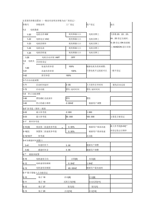
2.重要的参数设置表(一般没有说明该参数为出厂的设定)
参数号
参数说明
工厂设定
用户设定
备注
1-2电机数据
1-20
电机功率KW
视变频器大小
电机名牌上
当参数20、22、23、
24、25设定完成时,
将25设定ON按面板
上HANDON进行识别
1-22
电机电压VAC
视变频器大小
电机名牌上
1-23
电机的频率
丹佛斯FC51变频器设置指南

丹佛斯FC51变频器设置指南丹佛斯 FC51 变频器,在工业控制领域那可是个相当重要的角色。
对于不少搞电气控制的朋友来说,把它设置明白可不是一件简单的事儿。
今天,我就来给您详细唠唠这丹佛斯 FC51 变频器的设置指南。
先来说说我自己的一次经历吧。
有一回,我接到一个紧急任务,一家工厂的生产线突然停摆了,原因就是这丹佛斯 FC51 变频器出了问题。
我赶到现场一看,那叫一个乱啊!工人们都着急得不行,老板在旁边也是一脸的焦虑。
我赶紧静下心来,开始检查变频器的设置。
这丹佛斯FC51 变频器的设置,第一步就是要搞清楚您的具体需求。
比如说,您是要控制电机的转速呢,还是要实现精确的扭矩控制?不同的需求,设置的参数可大不一样。
接下来,就是连接硬件啦。
把电源线、控制线啥的都接好,可别接错喽,不然它可不听您使唤。
我记得有一次,一个新手把电源线和控制线弄混了,结果一通电,好家伙,直接冒了一股烟,把大家都吓了一跳。
设置参数的时候,那可得小心谨慎。
比如说,基本频率、最高频率、加速时间、减速时间等等,这些都得根据实际情况来调整。
就像有一次,我给一个风机调速,本来想着加速时间短一点能提高效率,结果设得太短了,风机启动的时候猛地一震,差点把旁边的零件都震掉了。
还有啊,丹佛斯 FC51 变频器有很多保护功能的设置也不能马虎。
过流保护、过载保护、过热保护等等,这些就像是给变频器穿上了一层防护服,能让它在恶劣的工作环境下也能稳稳当当的工作。
在设置过程中,您还得注意一些小细节。
比如说,参数的单位要搞清楚,有的是赫兹,有的是百分比,弄错了可就麻烦啦。
另外,设置完成后,一定要进行测试。
先空载运行一下,看看各项参数是不是正常,电机转得顺不顺。
有一回,我设置完没测试就直接上了生产线,结果运行起来电机抖动得厉害,又得重新返工,浪费了不少时间。
总之,丹佛斯FC51 变频器的设置需要您细心、耐心,按照步骤来,多注意细节,这样才能让它乖乖地为您工作。
希望我的这些经验能对您有所帮助,让您在设置变频器的时候少走弯路,顺顺利利的!。
I51AE__i510 Cabinet 0,25-2,2kW__v1-0__ZH
变频器 i550 ● ● ● ● ● ● ● ● ● ● ● ● ● ● ● ● ● ● ● ● ● ● ● ● ● ● ● ● ● ● ● ● ● ● ● ● ● ● ● ● ● ● ● ● ● ● ● ● ● ● ● ● ● ● ● ● ● ● ● ● ● ● ● ● ● ● ● ● ● ● ● ● ● ● ● ● V1.1 ●
变频器概览
i500 的比较
变频器 i510 i550
应用区域 电力供电系统
泵和风扇,传输设备,移动,卷绕,定型,工具和提升驱动 1/N/PE 1/3/PE 3/PE 1/N/PE 1/3/PE 3/PE 3/PE AC 170 ... 264 V AC 170 ... 264 V AC 340 ... 528 V AC 170 ... 264 V AC 170 ... 264 V AC 170 ... 264 V AC 340 ... 528 V 45 ... 65 Hz 45 ... 65 Hz 45 ... 65 Hz 45 ... 65 Hz 45 ... 65 Hz 45 ... 65 Hz 45 ... 65 Hz 0.25 ... 2.2 kW 1.7 ... 9.6 A 0.25 ... 2.2 kW 1.7 ... 9.6 A 0.37 ... 2.2 kW 1.3 ... 5.6 A 0.25 ... 2.2 kW 1.7 ... 9.6 A 0.25 ... 2.2 kW 1.7 ... 9.6 A 4.0 ... 5.5 kW 16.5 ... 23 A 0.37 ... 75 kW 1.3 ... 150 A
定义要求的输入变量
计算调节范围并决定额定点
基于额定数据确定电机
为变频器定义修正因素
基于额定数据确定变频器
变频器资料大全

变频器资料大全直接点击内容可以进入下载页面,下载是免费完全的,注册会员发3个帖即可下载,如果有急需要的朋友,可以和我QQ联系,通过QQ发给您,QQ:326107740.如果无法进入超连接,可以进/dispbbs.asp?boardid=16&Id=26987。
很高兴为同行做点事情。
最新变频器国家强制性标准与设计选型使用技术手册欧美品牌变频器ABB变频器acs510变频器中变压力控制系统的实现方法ABB ACS550-01变频器说明书a b b交流传动产品简介A B B变频器a c s350 A B B A C S550变频器产品样本A B B A C S100用户手册ABB ACS800变频器硬件手册ABB ACS800变频器应用程序指南A B B A C S800变频器标准应用程序7.x使用手册A B B A C S140用户手册ABB ACS100用户手册ABB ACS800-07 大功率硬件手册ABB ACS510系列变频器产品手册ABB ACS510系列变频器用户手册A B B A C S550系列用户手册A B B A C S510用户手册A B B140变频器手册A B B140变频器使用说明书ABB100变频器手册ABB ACS550-01变频器说明书A B B A C S800-07大功率硬件手册A C S800单传动选型样本A B B A C S800-02硬件手册A B B A C S350选型样本A B B直流D C S800硬件手册A B B A C S800-01硬件手册acs800与dcs通信测试指导ACS600技术样本ACS600标准应用程序A C S510变频器中变压力控制系统的实现方法A C S400变频器用户手册A B B中压变频器选型数据表A B B A C S150变频器技术手册ABB DCS500_DCS600直流传动系统资料样本ABB DCR600 选型安装及操作手册ABB DCC600 系统描述ABB ACS800 自定义编程应用程序指南ABB ACS800变频器应用程序指南ABB ACS800-01(壁挂)硬件手册A B B A C S604_607单传动硬件手册A B B A C S601单传动硬件手册A B B A C S800-02(立式)硬件手册A B B中压变频器选型数据表A B B D C S600技术数据A B B D C S500B技术数据A B B A C S800风机泵类控制固件手册(P F C)A B B A C S800-17硬件手册ABB ACS800-11 硬件手册ABB ACS800-07 大功率硬件手册ABB AC S800-04硬件手册ABB A CS 550变频器产品样本ABB ACS800-04P 固件手册ABB ACS1000技术样本(英文)ABB(acs510\acs550\acs100\acs150\acs800-02\acs800-04p\acs800-04\acs1000\acs350)变频器说明书A B B A C800M控制与I-O产品说明书A B B A C S800-02硬件手册A B B A C S550用户手册A B B A C S变频器说明书下载ABB变频器资料AB变频器ab powerflex700交流变频器简介AB PowerFlex4交流变频器简介ABB 中压变频器选型数据表ab powerflex4变频器技术手册AB PowerFlex700交流变频器产品手册.PowerFlex 700 交流变频器用户手册PowerFlex400变频器ABpowerflex(pf4\pf40\pf400\pf70\pf700)变频器说明书PowerFlex 400 变频器用户手册P o w e r F l e x70变频器用户手册.P o w e r F l e x家族手册P o we r F l e x 7000中压变频器P o we r F l e x 700技术数据PowerFlex 400P 矢量型交流变频器技术手册PowerFlex 400 交流变频器快速入门指南P o w e r F l e x400交流变频器产品简介P o w e r F l e x400技术数据P o we r F l e x 70交流变频器快速入门P o we r F l e x70技术数据PowerFlex 40P 交流变频器快速起动PowerFlex 40P 交流变频器技术数据P o we r F l e x 40P 交流变频器产品介绍P o w e r F l e x4M 技术数据PowerFlex 4_40 技术数据PowerFlex 4 交流变频器用户手册P o we r F l e x700用户手册P o we r F l e x70用户手册Po we r F l e x40用户手册Po we r F l e x4用户手册1336 PLUS II 产品介绍1336 PLUS II 变频器用户手册1336P L U S I I变频器1336I MPA C T 产品介绍AB 1336 PLUS II变频器使用说明书AB 1336Impact AC变频器选型指南AB 1336PLUSII变频器选型指南AB PowerFlex4变频器技术手册AB PowerFlex4交流变频器简介PowerFlex 70 交流变频器-技术手册PowerFlex 700 交流变频器-技术手册AB 变频器用户手册PowerFlex400交流变频器技术规范P o w e r F l e x400安装使用手册A B-P F70变频器说明书AB-160 SSC变速控制器(B系列)用户手册AB-1336PLUS II变频器无速度传感器矢量控制用户手册AB工程型变频器PF700S User Manual 3.01(用户手册)下载AB工程型变频器PowerFlex700S技术数据下载西门子变频器西门子s7-200模拟软件S I N A MI C S S120调试手册SINAMICS S120调试手册西门子变频器G110 简明操作说明书西门子变频器MM410操作手册西门子变频器MM430操作手册西门子变频器MM430应用手册西门子通用变频器应用实例手册西门子(m m420\m m430\m m440)变频器说明书西门子M M440变频器手册西门子M M 4307.5kW-250kW风机泵类专用型变频西门子M M440操作说明书MM430变频器手册西门子410420430440变频器说明书西门子电源供电交流小变频S I N A M I C S G110新品介绍西门子变频器S I N A M I C S G150产品样本M M440简明安装调试手册M M430中文使用说明书M M410使用大全西门子变频器MM420操作手册SIMOVERT MASTERDRIVES MC 装机装柜型DC-ACSIMOVERT MASTERDRIVES MC 增强型DC-ACSIMOVERT MASTERDRIVES MC 增强型AC-ACSIMOVERT MASTERDRIVES MC 书本型DC-ACSIMOVERT MASTERDRIVES MC 书本型AC-ACSIMOVERT MASTERDRIVES 6SE70增强型变频器说明书SIMOVERT MASTERDRIVES 6SE70书本型变频器说明书MASTERDRIVES VC书本型和装机装柜型的V3.4.2版本My Documents\MM 420 中文使用说明书MASTERDRIVES VC增强型的V3.4.2版本MASTERDRIVES MC,增强型V2.41版本MASTERDRIVES MC,增强书本型V1.6版本MASTERDRIVES MC,增强书本型V1.6版本MASTERDRIVES MC,书本型装机装柜型V2.41版本西门子MM430 风机水泵负载专用变频器使用手册西门子440故障引起故障可能的原因下载:西门子运动控制(MC)变频器说明书施耐德变频器ATV 61同步与异步电机变频器安装手册ATV 71同步电机与异步电机变频器安装手册ATV 71和ATV 61 IP23 IP54工程型机柜式变频器ATV 61同步与异步电机变频器软件V1施耐德变频器ATV71系列产品选型指南施耐德ATS48软起动-软停止单元用户手册施耐德ATV71 变频器Uni-Telway中文手册施耐德ATV61 71 profibus-DP用户手册-中文ATV 302 异步电机变频器安装手册编程手册ATV 61同步与异步电机变频器安装手册ATV 61中压电机用变频器系统选型指导ATV 21异步电机变频器用户手册ATV78变频器产品目录06ATV61高级多泵卡VW3A3 503 用户手册ATV61LonWorks卡VW3A3 312 用户手册ATV61BACnet卡VW3A3 315 用户手册ATV61 普通多泵卡用户手册Altivar 61异步电机变频器安装手册2 A l t i v a r61异步电机变频器安装手册1A T V68编程手册ATV58变频器用户编程手册施耐德ATV68 编程手册ATV58泵切换卡用户手册ATV38变频器中文用户编程手册Altivar28变频器说明书ATV31变频器编程手册A T V58泵切换卡用户手册AT V31变频器编程手册AT V31变频器安装手册AT V28变频器产品简介A T V11用户手册A T V68编程手册A T V58F变频器用户手册施耐德变频器说明书ATV31调试手册施耐德变频器ATV31变频器选型目录施耐德变频器A T V31变频器选型目录A T V31调试手册ATV28 变频器产品目录施耐德异步电动机变频器用户手册施耐德变频器shouce丹佛斯变频器丹佛斯变频器v l t2900英文操作说明丹佛斯变频器V LT2800设计指南丹佛斯变频器FCM300英文操作说明丹佛斯变频器FCM300英文操作说明丹佛斯F C D300I n s t r u c t i o n丹佛斯f c d300说明书Dan foss(丹佛斯) VLT5000一般技术数据Dan foss(丹佛斯) VLT5000技术说明Danfoss(丹佛斯) VLT5000技术功能(参数600-631).Danfoss(丹佛斯) VLT5000操作说明Danfoss(丹佛斯) FCM300说明书丹佛斯danfoss(vlt2800\vlt5000\vlt7000)变频器说明书丹佛斯变频器F C300中文操作说明丹佛斯变频器F C300设计指南.丹佛斯变频器FC51 快速指南意科变频器意科SINUS-PENTA变频器资料伦次变频器伦次变频器说明书伦次变频器说明书伟创变频器伟创变频器说明书伟肯变频器说明书欧陆变频器欧陆变频器说明书日本变频器安川变频器安川Varispeed G7系列使用说明书8安川Varispeed G7系列使用说明书7安川Varispeed G7系列使用说明书6安川Varispeed G7系列使用说明书5安川Varispeed G7系列使用说明书4安川Varispeed G7系列使用说明书3安川Varispeed G7系列使用说明书2安川Varispeed G7系列使用说明书1安川V a r i s p e e d L7系列使用说明书安川V1000使用说明书安川VS-606V7变频器使用说明书安川F7变频高效节能型矢量控制器系安川G7通用高性能矢量控制型变频器系列安川变频器说明书安川变频器说明书三菱变频器三菱变频器说明书三菱变频器调试软件三菱变频器说明书三菱FR-A520540 0.4-55K变频器手册[推荐]三菱变频器说明书下载三菱变频器A500中文手册富士变频器FUJI FVR-E11S系列紧凑型变频器FUJI FRENIC-Mini系列小容量通用紧凑型变频器富士变频器说明书FUJI VP系列风机水泵专用变频器三肯变频器三垦变频器说明书三垦变频器说明书日立变频器日立变频器说明书日立变频器说明书松下变频器松下变频器V F-8Z系列选型资料松下变频器说明书松下变频器说明书东芝变频器东芝变频器(VFS11通用型)使用说明书东芝变频器(VFP7风机水泵专用型)使用说明书东芝变频器(V F N C1简易型)使用说明书东芝变频器(V F A S1)使用说明书东芝变频器(VFA7高性能重载型)使用说明书东芝tosvert(vf-a7\vf-nc1\vf-p7\vf-s9\vf-s11)变频器说明书欧姆龙变频器欧姆龙omron(3g3rv\3g3ev\3g3mv)变频器说明书明电舍变频器明电舍(VT240EL \VT240S\VT230S)变频器说明书明电变频器说明书明电舍(VT240EL \VT240S\VT230S)变频器说明书松下电工变频器日本松下电工变频器说明书松下变频器说明书台韩变频器LG变频器LG iG5A变频器说明书LG iC5系列变频器中文说明书L S(L G)产电i v5系列变频器使用说明书L S(L G)产电i S5系列变频器用户手册L S(L G)产电i P5A变频器说明书(中文)L S(L G)产电I H系列变频器用户手册LS(LG)产电iC5超小型变频器产品介绍(中文)LS(LG)产电EMPR电子式电力保护继电器介绍(中文)L S(L G)产电变频器i P5说明书(中文)L S(L G)变频器产品应用范例LS(LG) 矢量变频器iV5产品介绍(中文)LS(LG) 经济型变频器iG5产品介绍(中文)LS(LG) 经济型变频器iG5A产品介绍(中文).LS(LG) 高性能变频器iS5产品介绍(中文)L S(L G) 风机水泵专用型变频器i P5产品介绍(中文)L S(L G) 变频器i G5A说明书LGIG5变频器说明书(中文版)LGIG5变频器说明书(中文版)lg(ls)iS5-De vice Ne t选件板说明书L GI G5变频器说明书(中文版) LG IV5变频器说明书(中文版).LG IS5变频器说明书(中文版). L G I H变频器说明书(中文版).L G变频器I G5LG(LS)(lg-ig5\lg-ih\lg-ip5\lg-is5\lg-iv5)变频器说明书LG变频器资料东元变频器东元变频器说明书台达变频器台达变频器说明书台达变频器V F D-L中文手册台达变频器V F D-G中文手册台达变频器V F D-A中文手册台达变频器F系列说明书E2台达变频器说明书D e l t a V F D-V变频器(A M D)使用说明书D e l t a v f d-p变频器(A M D)使用说明书Delta VFD-L型录Delta VFD-B(使用说明书)变频器(AMD) D E L T A a s d a-b B系列伺服使用说明书台达变频器S系列说明书台达变频器M系列说明书台达变频器F系列说明书(1).台达A S D A-B交流伺服系统使用手册台达A S D A-B交流伺服系统简易手册台达ASDA-B交流伺服系统安装手册Delta VFD-SERIES 变频器(AMD)使用说明书Delta vfd-md系列变频器(AMD)使用说明书台达塑胶空油压机专用型VFD-G系列说明书台达内置P L C型型变频器V F D-E系列说明书台达J A G E R电主轴全系列手册台达ASDA-A交流伺服系统使用手册Delta VFD-E 变频器(AMD)使用说明书台达B变频器中文说明书台安变频器台安N2系列变频器手册台安E V300变频器系列应用软件台安N2说明书台安E2系列变频器手册台安N2变频器中文说明书台安变频器说明书国产变频器爱默生变频器爱默生e m e r s o n(t d3000\t d1000\t d900)变频器说明书华为变频器说明书艾默生ES变频器参数表EV3100电梯专用变频器用户手册爱迪生变频器说明书安amp1000变频器说明书爱默生变频器说明书普传变频器普传168系列使用说明书(中文).普传PI7600_7800系列使用说明书(中文).普传(pi7600\pi168g\pi7000\pi7100)变频器说明书普传变频器在供水控制系统中的应用普传PI168变频器说明书普传PI7000_7100系列使用说明书(中文).普传P I97G.V4说明书(中文).普传P I7000变频器说明书阿尔法变频器A L P H A6000使用说明书A L P H A3300通用型变频器说明书ALPHA5000使用说明书阿尔法alpha(3300\2000g\6000\2800\2000p\2000z\系列说明书A L P H A2800使用说明书A L P H A2000G使用说明书阿尔法变频器说明书阿尔法说明书阿尔法2000G系列说明书科姆龙变频器科姆龙变频器说明书安邦信变频器安邦信A MB(P7\G7\P9\G9系列)变频器说明书安邦信G7变频器说明书康沃变频器康沃(g2\g3\s1\zs-zc1)变频器说明书英威腾变频器英威腾变频器说明书英威腾变频器说明书森兰变频器森兰SB100系列变频器使用手册森兰SB61Z 注塑机变频器使用手册森兰变频器说明书森兰变频器资料易能变频器易能E D S1000变频器说明书易能E D S2800变频器说明书易能变频器说明书微能变频器微能W IN-9G说明书微能WIN-VB系列变频器使用说明书微能W I N-V B系列变频器使用说明书微能W I N-9V变频器使用说明书微能WIN-9V变频器使用说明书微能WIN-HV系列高压变频器使用说明书微能win(9i-v\9l-v\9u-v\9u-rdb\hv-v\9v-t)变频器说明书微能变频器说明书微能WIN-VC 高性能强功能矢量控制变频器海利普变频器海利普hlp(a系列\c系列\sv系列\v系列\j系列\nv系列\p系列)变频器说明书海利普变频器说明书风光变频器风光变频器说明书四方变频器四方变频器说明书神源变频器神源SY5000变频器用户手册神源SY4000变频器通用型用户手册神源SY4000系列增强型变频器终述神源SY4000系列增强型变频器用户手册-中文目录神源S Y4000系列增强型变频器控制面板键盘操作神源S Y4000系列增强型变频器接线神源SY4000系列增强型变频器功能代码参数说明神源SY4000系列增强型变频器安装和使用方法神源SY4000变频器通用型用户手册神源sy(sy5000p\sy5000\sy5000g\sy4000)变频器说明书神源变频器说明书正频变频器正频PDH系列高频高速型变频器正频变频器说明书正弦变频器说明书威科达变频器威科达V5系列变频器说明书威科达变频器说明书西威变频器西威变频器说明书西威变频器资料西威变频器资料(续)惠丰变频器惠丰(f1000-g\f1000-m\f1500-g\f1500-p)变频器说明书格力特变频器格立特变频器说明书格力特(vc3100\vc3200)变频器说明书富凌变频器富凌DZB(100P\70B\100M\60J\200&300)变频器说明书富菱变频器说明书时代变频器时代tvf(tvf7000\tvf7100\tvf1000\tvf2000)变频器说明书佳灵变频器佳灵(jp6c-j9\j9zn\nkb\jp6c-t9\jp6c-zt9\jp6c-z9\jp6c-t9c\jcs\jcp\jcc\jcf)变频器说明书蓝海华腾变频器蓝海华腾(v5-h\v5-i\v5-t\v5-w\v6-h\v6-t)变频器说明书海蓝华腾变频器说明书传动之星变频器传动之星(sd-5l\sd-5l4t-s)变频器说明书传动之星变频器贝西变频器贝西bc(bc-1000\bc-2000\bc-2300)变频器说明书博世力乐士变频器博世力乐士fe系列变频器说明书力士乐变频器说明书科比变频器科比变频器说明书依尔通变频器依尔通(fdu\vfx)变频器说明书正阳变频器正阳sysc(zy292t\zy612g)变频器说明书鹰垦变频器鹰垦变频器说明书德瑞斯变频器德瑞斯(1000m\2000\2800\3000)变频器说明书优利康变频器优利康yd(2000\3000)变频器说明书尤尼康UCLS系列变频器说明书YOLICO3000系列变频器说明书SSD变频器SSD变频器说明书RB变频器RB变频器说明书菱科变频器菱科LK800系列单相220V变频器说明书菱科LK600英文说明书菱科LK600系列变频器中文说明书罗升变频器罗升变频器说明书东旭变频器东旭变频器说明书PE变频器PE(SD700、V5)变频器说明书塞普变频器塞普变频器说明书赛普变频器说明书阳冈变频器阳冈e1系列变频器说明书星河变频器星河变频器说明书乐邦变频器乐邦变频器说明书能普变频器能普变频器说明书加能变频器加能变频器说明书西林变频器西林变频器说明书创杰变频器创杰变频器说明书金肯变频器金肯变频器说明书易驱变频器易驱变频器说明书日业变频器日业变频器说明书日业变频器说明书日锋变频器日锋变频器说明书方禾变频器方禾变频器说明书百德福变频器百德福变频器说明书山宇变频器山宇变频器说明书德力西变频器德力西变频器说明书韦尔变频器韦尔AC30变频器说明书伊顿变频器伊顿S V X9000变频器产品指南伊顿S V X9000系列变频器说明书威尔凯变频器威尔凯W KS系列矢量型变频调速器产品详情威尔凯W KJ系列迷你型变频调速器产品详情\威尔凯WKF系列通用型变频调速器产品详情威尔凯WKE系列专用型变频调速器产品详情欧瑞变频器欧瑞传动K2000暖通系列说明书欧瑞传动F2000-M中频系列说明书欧瑞传动E1000系列通用型变频器说明书欧瑞(E1000\F1000G\F2000G\F2000M)变频器说明书.德弗变频器德弗传动D V600系列矢量变频器使用说册德弗传动D V300系列变频器使用说册SEW变频器SEW变频器说明书。
51仿真器原理图及制作过程
51仿真器原理图及制作过程
--------------------------------------------------------------------------------
51仿真器原理图及制作过程
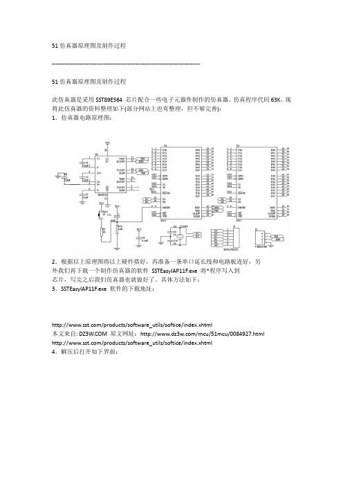
此仿真器是采用SST89E564 芯片配合一些电子元器件制作的仿真器。
仿真程序代码63K,现将此仿真器的资料整理如下(部分网站上也有整理,但不够完善):
1.仿真器电路原理图:
2.根据以上原理图将以上硬件搭好,再准备一条串口延长线和电路板连好,另
外我们再下载一个制作仿真器的软件SSTEasyIAP11F.exe 将*程序写入到
芯片,写完之后我们仿真器也就做好了。
具体方法如下:
3.SSTEasyIAP11F.exe 软件的下载地址:
/products/software_utils/softice/index.xhtml
本文来自: 原文网址:/mcu/51mcu/0084927.html
/products/software_utils/softice/index.xhtml
4.解压后打开如下界面:
5.按下图操作,点击红色箭头:
6.得到如下界面,我们先选择仿真芯片为SST89E564,然后点击OK
7.得到下图后,我们点击确定,上电.
8.当出现下图红色箭头所示,表示连接成功.
9.接下来我们开始下载*程序,单击红色箭头的Download SoftICE
10.如下图所示,我们点击OK开始下载*程序
11.整个下载过程不到1分钟就完成了,就这样一个仿真器做好了
本文来自: 原文网址:/mcu/51mcu/0084927.html。
- 1、下载文档前请自行甄别文档内容的完整性,平台不提供额外的编辑、内容补充、找答案等附加服务。
- 2、"仅部分预览"的文档,不可在线预览部分如存在完整性等问题,可反馈申请退款(可完整预览的文档不适用该条件!)。
- 3、如文档侵犯您的权益,请联系客服反馈,我们会尽快为您处理(人工客服工作时间:9:00-18:30)。
Application Note, V 2.0, Sept. 2005AP0803620XC866Optimized Space Vector Modulation and Over-modulation with the XC866MicrocontrollersXC866Revision History: 2005-09V 2.0 Previous Version: -Page Subjects (major changes since last revision)Many Updated for the XC866SW Updated for the XC866, Uses DAvE and C/Assembly mixController Area Network (CAN): License of Robert Bosch GmbHIntroduction1 IntroductionThis Application Note shows how the CAPCOM6 module found in many Infineon 8, 16 and 32-bit microcontrollers can be used to implement space vector modulation for three-phase voltage control inverter applications. A simple algorithm for overmodulation is also demonstrated. The alogorithms of this application note are implemented on the Infineon XC866 8051 based 8-bit microcontroller.Space Vector Modulation (SVM) is a method of producing 3-Phase sinusoidal voltages. The primary use for SVM is in motor control applications (mainly for induction and brushless DC motors). However SVM can also be used in Uninterruptible Power Supply (UPS) applications. SVM is popular because it generates higher voltages with low total harmonic distortion than traditional sinusoidal PWM techniques. Another advantage of SVM is that it works very well with field oriented (vector control) schemes for motor control.Figure 1 shows a typical motor control application where this Application Note could be useful.Figure 1 Typical Motor Control ApplicationSinusoidal Voltage Generation & Capture/Compare Units2 Sinusoidal Voltage Generation & Capture/CompareUnitsThe capture/compare units of Infineon 8, 16 & 32-bit microcontrollers (CAPCOM6) are designed to control many types of motors. For controlling 3-phase motors, the capture/compare unit can be used to generate the 6 PWM signals needed to drive a 3-phase inverter, including the necessary dead-time needed to eliminate shoot-through current on each phase.PWM can be used to create a sinusoidal voltage by creating a fixed frequency signal and adjusting the duty cycle. If the duty cycle varies sinusoidally, so will the output voltage. It is always assumed that the inductance of the motor will filter the PWM into a smooth signal as shown in Figure 2.Capture/Compare units are designed to create variable duty cycle PWM signals. Actually it is only the “compare” feature of a Capture/Compare unit that is used for PWM generation. The Capture/Compare unit contains a timer and several compare registers. When the timer value is the same as the compare register value, an output pin is either pulled high or low. So the duty cycle of the output signal follows the compare value linearly. The CAPCOM6 unit has 3 compare registers and a timer that can count up from 0 to any specified 16-bit “period” value. When the timer reaches the period value, it reverses direction and counts down to 0. This is useful for generatingcenter aligned PWM as shown in Figure 3.Sinusoidal Voltage Generation & Capture/Compare UnitsFigure 3 Center Aligned PWM Produced the CAPCOM6 UnitTo aid in 3-phase inverter control, the CAPCOM6 modules are capable of producing 6 compare outputs. Fore each of the 3 Compare Channels there are 2 output pins. The pins are often labeled CCx and COUTx (where x = 0, 1, 2). The polarity of each of the six pins is individually programmable. In addition to this, a programmable amount dead-time can be automatically inserted to delay the passive to active transition of both pins. This prevents shoot-through current which can destroy the inverter. Figure 4 shows how a single CCx and a COUTx pin can be used to control one phase of an inverter.Figure 4 Dead-Time Generation (CCx and COUTx with opposite polarity)Methods for Producing Sinusoidal Voltages 3 Methods for Producing Sinusoidal VoltagesThe following sections describe different methods of generating three phase sinusoidal voltages. Section 3.1 briefly describes a simple method for generating sinusoidal voltages using sinusoidal duty cycles. This method has been around for quite some time and has been the subject of other application notes. The biggest disadvantage to this method of voltage generation is that the maximum amplitude of the fundamental frequency of the generated line-to-line voltage is only about 86% of the inverter DC rail voltage.Section 3.2 describes the theory behind SVM. SVM is a method of sinusoidal voltage generation which generates voltages whose amplitude of the fundamental frequency of the line-to-line voltage is equal to the full DC rail voltage. The total harmonic distortion of SVM is also less.Section 3.3 describes over-modulation. Over-modulation is a way of increasing the amplitude of the fundamental frequency even higher (to about 1.12 times the rail voltage). Unfortunately over-modulation introduces more low order harmonics and increases the total harmonic distortion.3.1 Sinusoidally Weighted PWM (SWPWM)One simple way to create three phase sinusoidal voltages is to create a signal which has a very high constant frequency (compared to the frequency of the desired sinusoid) and a sinusoidally weighted duty cycle. This method of sinusoidal PWM will be referred to as SWPWM. SWPWM can be implemented very simply by placing sinusoidally weighted values into the three compare registers of the CAPCOM6 module. The CAPCOM6 module can then be used to control the 6 transistors that make up the inverter.SWPWM has the advantage of requiring very little calculation (assuming the appropriate look-up tables are used). Each of the three phases can be made to generate a sinusoid which is 120º out of phase. The sinusoidal phase voltages generate sinusoidal line-to-line voltages and sinusoidal line-to-neutral voltages when connected to a balanced star connected load as shown in Figure 5. Scaling the voltages can be done easily with a multiply, or through some trigonometric tricks.It should be noted that phase voltage is the voltage at one motor terminal measured with respect to the inverter negative rail voltage. Line-to-line voltage is the voltage at one motor terminal measured with respect to another terminal. Line-to-neutral voltage is the voltage at one motor terminal measured with respect to the neutral (center of the star connected load).Methods for Producing Sinusoidal VoltagesThe major disadvantage to this method of sinusoid generation is that the magnitude of the fundamental frequency of the line-to-line voltage is only ~86.6% of the inverter rail voltage.Figure 6 shows a frequency spectrum plot of the generated line-to-line voltages when creating this type of sinusoid. Notice that in addition to the fundamental frequency, the switching frequency (~20 kHz) harmonics also have a significant magnitude. ArrayFigure 5 Sinusoidal PWM values produce sinusoidalMethods for Producing Sinusoidal Voltages3.2 Space Vector Modulation (SVM)SVM is a more sophisticated PWM method which provides a higher voltage to the motor (with lower total harmonic distortion). Consider the three phase inverter of Figure 7. Note that whenever transistor A+ is on, transistor A- must be off, and visa versa, to prevent damaging shoot-through current. This makes it easy to adopt a simple notation for describing the state of the inverter. For example, the state when transistors A+, B-, and C- are “on” (and of course A-, B+, and C+ are “off”) can be represented with the notation (+, -, -). The state where transistors A-, B+, and C- areon is denoted by (-, +, -).Methods for Producing Sinusoidal VoltagesUsing this notation, consider the following sequence of states:(+, -, -), (+, +, -), (-, +, -), (-, +, +), (-, -, +), (+, -, +)Running the inverter through this switching sequence will produce the line-to-neutral voltages shown in Figure 8. This mode of operation is called “six-step mode”. Operating in six-step mode allows you to use the full capabilities of the inverter. If you were to perform an FFT on the line-to-line voltages produced in six-step mode, you would find that the amplitude of the fundamental frequency is actually greater than the inverter rail voltage. Unfortunately six-step mode also creates high magnitude low order harmonics which cannot be filtered by the motor’s inductance.Space vector modulation is based on six-step mode, but smoothes out the steps through some sophisticated averaging techniques. For example, if a voltage is required that is between two step voltages, the corresponding inverter states can be activated in such a way that the average of the step voltages produces the desired output. To develop the equations needed to generate this averaging effect, the problem is transformed into an equivalent geometrical problem. The first step in this re-definition is to transform the inverter voltages of six-step mode into space vectors. Space vectors are similar to phasors in that they are denoted by a magnitude and an angle. It is important to note that space vectors are not phasors. A Phasor is used to represent something that varies sinusoidally in time. A space vector is used to represent something that varies sinusoidally in space with respect to an angle. Forthis reason space vectors are sometimes referred to as space phasors.Methods for Producing Sinusoidal VoltagesIn general, any three time varying quantities, which always sum to zero and are spatially separated by 120º can be expressed as a space vector. Array Figure 8 Line-to-Neutral Voltages in Six-Step ModeSince the three line-to-neutral voltages sum to zero, they can easily be converted into a space vector (u s) using the following transformation:u s = V an(t) e j0 + V bn(t) e j2π/3 + V cn(t) e-j2π/3Since the components of space vectors are projected along constant angles (0, 2π/3,and -2π/3), it is easy to graphically represent a space vector as shown in Figure 9.Methods for Producing Sinusoidal VoltagesUsually, when creating space vectors, the three time-varying quantities are sinusoids of the same amplitude and frequency that have 120º phase shifts. When this is the case, the space vector at any given time maintains its magnitude. As time increases, the angle of the space vector increases, causing the vector to rotate with frequency equal to the frequency of the sinusoids.If the voltages of Figure 8 are converted into a space vector and plotted on the complex plane, it can be seen that the space vector takes on one of 6 distinct angles as time increases (instead of rotating smoothly as it would if the voltages were pure sinusoids). Figure 10 shows the values that the space vector assumes as time increase.The goal of space vector modulation is to generate the appropriate PWM signals so that any vector (u s) can be produced. Consider a space vector voltage u s located in the sector defined by u1 and u2. We can approximate u s by applying u1 for a percentage of time (t a) and u2 for a percentage of time (t b) such that:t a*u1 + t b*u2 = u sThis leads to the following formulas for t a and t b:t b = 2U(3-½)sin(α) where U = |u s| (Modulation Index)t a = U[cos(α) – (3-½)sin(α)] α = ∠u sMethods for Producing Sinusoidal VoltagesSo given a space vector of angle α (in sector 0) and modulation index U, the approximation can be constructed by applying vectors u 1 and u 2 for percentage of times t a and t b , respectively. Graphically this is represented in Figure 11. If the vector is in another sector, it can be rotated by a multiple of π/3 radians until it is in sector 0. The times can be calculated and then applied to the appropriate inverter states.Figure 10Space Vectors of Line-to-Neutral Voltages in Six-Step ModeFigure 11Approximation of the Space Vector u s by t a and t bLike many other types of PWM, space vector modulation uses pulses of constant frequency (carrier frequency) with variable duty cycle. The carrier frequency is often chosen so that it is high enough to be out of the audible range and produces littleMethods for Producing Sinusoidal Voltages current ripple, but not so high as to create excessive switching losses. The period of the carrier will be called T0.To approximate the u s in Figure 11, the inverter state that corresponds to u1 should be active for t a*T0 seconds, and the inverter state that corresponds to u2 should be active for t b*T0 seconds. When the modulation index is sufficiently small ( less than ½(3½)), the sum of t a and t b will be less than one. This means that t a*T0 + t b*T0 is less than T0. So for the left over time no voltage should be applied to the motor. The “left over” time will be referred to as t0. To be more formal:t0 = T0 (1– t a – t b)There are two ways to apply no voltage to the motor. The first way is to simply connect all three phases to the negative rail of the inverter. This will be called inverter state 0 and the corresponding switching pattern is (-, -, -). The second way to apply no voltage to the motor is to connect all three phases to the positive rail of the inverter. This will be called inverter state 7 and the corresponding switching pattern is (+, +, +). So, to approximate the voltage u s during the PWM carrier period, the pulses and timing shown in Figure 12 could be used. To obtain a better total harmonic distortion, a slightly different method of applying the switching states can be used. If the t0 time is split in half and applied at the beginning and the end of T0, then a more symmetric distribution of pulses can be generated. This method is known as symmetric or center-aligned space vector modulation. Figure 13 shows how symmetric space vector modulation is implemented over two consecutive carrier periods.Methods for Producing Sinusoidal VoltagesFigure 12Asymmetric PWM for SVMFigure 13SVM using Symmetric PWMMethods for Producing Sinusoidal VoltagesThe pulses shown in Figure 13 are very similar to those shown in Figure 3, and can be easily generated using the CAPCOM6 module. As shown in Figure 13, the switching frequency is 1/(2*T0).When the modulation index exceeds ½(3½), the value of t0 can become negative (depending on the angle). Since it is not physically possible to apply one of the zero vectors for negative time, the maximum modulation index for space vector modulation is approximately 0.866. Graphically, this means that for space vector modulation to work properly, the magnitude of the reference space vector, u s, must be small enough to ensure that the vector is totally contained inside the hexagon shown in Figure 10. When symmetric space vector modulation is implemented with a modulation index of 0.866, the ideal phase voltage (after filtering by the motor) as shown in Figure 14 is generated. The phase voltage of Figure 14 has the same shape as the compare values that should be used. These unusual voltages create sinusoidal line-to-neutral voltages (as expected) and sinusoidal line-to-line voltages are also generated.Methods for Producing Sinusoidal VoltagesAs shown in Figure 14, SVM can create sinusoidal line-to-line voltages which have amplitudes equal to the inverter rail voltage, even though the modulation index is only 0.866. SVM has also been proven to produce lower current harmonics and torque ripple than SWPWM. Figure 15 shows the frequency spectrum of the line-to-line voltage of a SVM simulation with modulation index of approximately 0.866. As Figure 15 shows, the magnitude of the fundamental frequency is higher and the magnitude ofthe switching frequency is lower than Figure 6.Methods for Producing Sinusoidal Voltages3.3 Over-modulationIt has been proven that SVM can produce higher amplitude voltages than SWPWM, even if the modulation index is limited to 0.866. There are several techniques that can be used to extend this modulation index range. These techniques are referred to as over-modulation.Figure 16 shows a graphical representation of the problem. In Figure 16, sector 0 from the hexagon of Figure 10 is shown. Over-modulation is needed when the modulation index (the length of the reference space vector, u s) causes the head of the vector to belocated outside of the hexagon.Methods for Producing Sinusoidal VoltagesIn Figure 16, t 0 will only become negative if α1 < α < α2. A simple method of overmodulation is based on the angle, α, of the reference vector u s , as shown in Table 1.Figure 16 Graphic Depiction of a Space Vector with U > 0.866Table 1Angle and Magnitude to use for Over-modulation Angle of u SαLength of u S Modulation IndexAngle to use for SVMα2 < α < α1 U α α1 < α < π/6 U α1 π/6 < α < α2 Uα2Methods for Producing Sinusoidal VoltagesWhen α is less than α1, space vector modulation can be performed as usual using U and α. Since the head of u s is inside the hexagon, t0 will be greater than zero and everything will work properly. When α is between α1 and π/6, t0 will be less than zero. To avoid this, SVM can be performed using α1 and U. This will yield a t0 of zero. When α is between π/6 and α2, again, t0 will be less than zero. To avoid this, SVM can be performed with U and α2. Once α is greater than α2, SVM can be performed normally again with α and U.This method of over-modulation will obviously not produce line-to-line and line-to-neutral voltages which are as ‘clean’ as normal space vector modulation, but it will allow the modulation index to exceed 0.866. If the frequency spectrum of the PWM is analyzed then it can be seen that the fundamental frequency does increase beyond what is capable using just SVM. Of course, the total harmonic distortion will increase. When the modulation index reaches 1.000, over-modulation will produce signals equivalent to six-step mode. In six-step mode the magnitude of the fundamental frequency of the line-to-line voltage is ~112% of the inverter rail voltage.The values of α1 and α2 can be determined by examining Figure 16:δ = acos(½(3½)/U)α1 = π/6 - δ whereα2 = π/6 + δFigure 17 shows the magnitude of the fundamental frequencies produced using SVM, over-modulation and SWPWM.Methods for Producing Sinusoidal VoltagesFigure 17 Fundamental Frequency of Line-to-Line VoltagesMicrocontroller Implementation of SVM 4 Microcontroller Implementation of SVMMicrocontroller implementation of SVM and over-modulation can be very difficult. The SVM equations can be complicated, and over-modulation adds to the complexity. Proper scaling variables can make the computations much easier. Section 4.1 describes the variable scaling and resolution used for a SVM and over-modulation implementation using the Infineon XC866 8051 based 8-bit microcontroller. An optimized flow chart for SVM and over-modulation is also given.There are several implementation options which effect SVM performance and CPU load. Section 4.2 also discusses these options and possible trade-offs a designer should consider.Section 4.3 shows the results of the SVM and over-modulation implementation with the XC866. Conclusions are also given.4.1 Variable Scaling and Resolution and Software OptimizationTo implement SVM, the microcontroller must receive (or perhaps even generate) a reference space vector. It is usually convenient if the space vector is given in terms of a magnitude (U) and an angle (α). Given U and α the switching times can be calculated by the formulas:t b = 2U(3-½)sin(α)t a = U[cos(α) – (3-½)sin(α)]t0 = T0 – t a - t bThe first step should be to decide on a switching frequency. In many cases, PWM frequencies above 20 kHz are considered to be ideal. Since the CAPCOM6 unit will operate as an up/down counter, this means that the timer period value should be above 40 kHz.To keep the calculations simple for an 8-bit microcontroller, T0 should be represented as an 8-bit value. This means that the period value for the CAPCOM6 Timer (Timer 12) should be set to 0x00FF. The XC866 operating from the internal oscillator and at the maximum PLL factor runs at 26.67MHz. So setting up the CAPCOM6 Timer 12 in symmetric PWM mode with a period value of 0x00FF and a divide by 2 pre-scaler will enable 26 kHz PWM.It is also convenient if U is scaled to be an 8-bit value. U is a “per unit” value which means that it is always between zero and one, so the resolution of U will be 1/255 or 0.00392.Microcontroller Implementation of SVMSince the equations for t a, t b, and t0 are only valid for α between 0 and π/3, it would be easier if α is represented by an 11-bit value. If the most significant 3 bits can be used to indicate the sector, the least significant 8-bits can contain the angle within the sector with a resolution of π/765 radians or 0.235 degrees. This allows the formulas for t a, t b, and t0 to be valid for any α as long as only the low byte is used.A look-up table can be used for sine and cosine so that t a and t b can be calculated, but it would require less computation if the values of t a and t b for U = 1.0 (0xFF in fixed point) are stored in look-up tables. The values can then be looked-up and scaled for the appropriate value of U. If one creates a table of t a and t b for the 255 different values of α for the case when U = 1, it can be easily seen that the table for t a is exactly the same as the table for t b except in reverse. This means that only one table is needed. Table 2 shows the digital representation of the variables needed for SVM and over-modulation.Table 2 Representation of Variables needed for SVM and Over-modulationVariable DigitalRepresentation Engineering UnitResolutionCommentsU (|u s|)8-bit value(0x00 – 0xFF)1/255(~0.00392)Input Variableα(∠u s)11-bit value(0x0000 – 0x05FF)π/765 radians(~0.235 degrees)Bits 0-7 contain α, Bits 8– 10 contain sector (inputvariable)T08-bit value(0x00 – 0xFF) CCU timer resolution(100 ns)~19.6 kHz CarrierFrequency (fixed)t b8-bit value(0x00 – 0xFF) CCU timer resolution(100 ns)Stored in a tableTable contains t b forU = 1.0 (0xFF)t a8-bit value(0x00 – 0xFF) CCU timer resolution(100 ns)Stored in a tablet b table is used in reverset08-bit value(0x00 – 0xFF) CCU timer resolution(100 ns)Calculatedt0 = ~(U*t a+U*t b)/256α1 and α28-bit values(0x00 – 0xFF)π/765 radians(~0.235 degrees)Calculated as neededfrom δThe CAPCOM6 unit relieves the CPU of much of the computational work required for symmetric PWM generation. From Figure 13, the relationship between the compare values and t a, t b, and t0 can be determined. Table 3 shows how the compare valuesMicrocontroller Implementation of SVM for phases A, B, and C can be chosen based on the sector in which the reference vector is located.Table 3 Compare Values for Symmetric SVMSector Phase A CompareValue Phase B CompareValuePhase C Compare Value0 ½ t0 ½t0 + t a T0 – ½ t01 ½ t0 + t b ½t0T0 – ½ t02 T0 – ½ t0 ½t0 ½t0 + t a3 T0 – ½ t0 ½t0 + t b ½t04 ½ t0 + t a T0 – ½ t0 ½t05 ½ t0T0 – ½ t0 ½t0 + t aFortunately, T0 is 0xFF, so T0 – ½ t0 is simply ~½ t0, and t0 is simply ~(t a + t b). Figure18 shows the flow chart (optimized for execution time) for a microcontroller implementation of SVM and overmodulation.Microcontroller Implementation of SVMFigure 18 Microcontroller Implementation of SVM and Over-modulationMicrocontroller Implementation of SVM4.2 SVM Implementation OptionsThe compare registers of the CAPCOM6 peripheral have shadow registers that allow all of the compare values to be updated at once. When the compare registers are written to by the microcontroller, the values are actually stored in the shadow registers. If the Shadow Transfer Enable bit (STE12) is set, then the contents of the shadow registers are copied to the actual compare registers as soon as the timer (T12) reaches the period value (when counting up) or 0x0001 when counting down. This shadow latch mechanism ensures that the three compare values are updated simultaneously and it also guarantees that there are no disturbed pulses.Generally SVM is performed twice every switching period as shown in Figure 13. To properly implement this, the shadow latch transfers must occur when the compare timer reaches 0x0001 and when the compare timer reaches its period value. However many times SVM is implemented so that the compare values are only updated when the timer is 0x0001 to reduce CPU load and to keep the PWM symmetric. The user can decide which option best suits his needs.With most carrier based PWM methods, the microcontroller compare value calculation is synchronized with the carrier signal (the compare timer). This ensures a more consistent latency between the time that the new input values (u s) are received until the pulses are actually present on the output pins. This synchronization is usually accomplished by performing the SVM calculations after a compare timer interrupt. The CAPCOM6 module can generate interrupts when the compare timer reaches zero and when the timer reaches its period value. This is equivalent to having an interrupt at the beginning of every T0. Using these interrupts to trigger the SVM calculations will ensure a more consistent input to output latency.SVM and over-modulation have been implemented on the XC866. The actual SVM and over-modulation code was written in assembly language to optimize the execution speed. The assembly code is part of a larger project that includes C files for initialization and testing. A conditional assembly switch is also used to enable or disable over-modulation.When implementing SVM in a motor control application, there are many factors which will influence the CPU load. Table 4 shows some of the major factors and their impact on CPU load when using the algorithms of Figure 18. It should be noted that the switching frequencies shown in Table 4 can be obtained without changing the SVM algorithm. The only modification needed is a change of the CAPCOM6 Timer 12 pre-scaler. Table 4 shows only the CPU load for the SVM algorithm (the compare timerMicrocontroller Implementation of SVMISR) without a control loop. It also assumes that the XC866 is operating at 26.67 MHzfrom internal flash with one wait-state (6.67 MIPS).In addition to SVM and over-modulation, the demo code that accompanies this application note implements a simple control loop that allows the user to adjust thelength and velocity of the input vector. Two A/D channels are used to control the amplitude and frequency of the generated voltages.Table 4 CPU Load for SVM assuming 150 ns per Instruction CycleSwitchingFrequency6.5 kHz 13 kHz 26.0 kHzSVM only 7.6% 15% 30% SVM ExecutedOnce Per SwitchingPeriodSVMw/Overmodulation9.5% 19% 38%SVM only 15% 30% 61%SVM ExecutedTwice Per Switching PeriodSVMw/Overmodulation19% 38% 76%4.3 Results and ConclusionsThe source code that accompanies this application note was executed using the XC866 microcontroller evaluation board. To view the output, either the CCx or COUTx pins of the microcontroller can be connected to an external circuit as shown in Figure 19. Capacitors are used to filter the PWM outputs so the voltages will appear smooth when viewed by an oscilloscope. The source code for this application note uses two analog inputs to control the magnitude and frequency of the generated voltage. This portion of the code will be omitted or modified in most applications.Accompanying this application note are the source code files and an Excel spreadsheet which can be used to calculate the look-up table values if different dead-times are needed.。