T8000系列触摸屏温控器
MCT8000F88100F88200F8系列运动控制器

版权声明 深圳市摩信科技有限公司 保留所有权力
深圳市摩信科技有限公司(以下简称摩信科技)保留在不事先通知的情况下, 修改本手册中的产品和产品规格书的权力。摩信科技不承担由于使用本手册或本 产品不当,所造成直接的、间接的、特殊的、附带的或相因而生的损失或责任。 摩信科技具有对本产品的专利权、版权和其它知识产权。未经授权,不得直接或 者间接地制造、加工使用本产品及其相关部分。
警告:运动中的机器有危险!使用者有责任在机器中设计有效的出错处理和 安全保护机制,摩信科技没有义务或责任对由此造成的附带的或相因而生的损失 负责。
目录
目录
第一章 绪论……………………………………………………………………………………..…(1)
1.1 概述......................................................................................………………………………..(1) 1.2 电机类型简介...............................................................................……………………….…(2)
绪论
第一章 绪 论
1.1 概述
MCT8000F8/8100F8/8200F8系列控制器可以通过ISA/PCI总线或USB接口直接 与PC机相连接,不同型号的控制器连接方式不同。其中,MCT8000F8系列的接口 为ISA总线,MCT8100F8系列为PCI总线,而MCT8200F8是USB接口。由于采用了最 新的DSP和FPGA技术,这些控制器都具有高速通信功能、高频率的编码器计数功 能和低电磁辐射等特点。经过特殊的设计,所有的MCT8000F8/8100F8/8200F8控 制器都能基于主机运行或者脱离主机独立运行。借助于MCT8000F8的软件包,控 制器可以自动选择本地或互联网两种方式运行。有关详细情况可参考 《MCT8000FX/8100FX/8200FX系列运动控制器:软件使用手册》。
XMT8000说明书

XMT□—8000系列智能温度调节器使用说明书一、概述XMTX8000系列智能温度调节器是一种高性能、高可靠性的智能型工业调节仪表,广泛应用于机械、化工、陶瓷、轻工、冶金、石化、热处理等行业的自动温度控制。
主要特点•热电偶、热电阻、模拟量等多种信号自由输入,量程自由设置;•软件调零调满度,冷端单独测温,放大器自稳零,显示精度可优于0.2%FS;•热电阻单独测线阻,完全去除线阻影响;•模糊理论结合传统PID方法,控制快速平稳;•输出可选:继电器触点、SSR驱动电平、移相触发脉冲、过零触发脉冲和模拟量,另附二路可定义的报警触点输出;二、技术规格●输入规格(一台仪表即可兼容):热电偶:K、J、E、S、N、T、B、R、WRe热电阻:CU50、PT100线性信号:0-5V、1-5V、0-10mA(需外接分流电阻)、4-20mA(需外接分流电阻)等●测量范围:K(-50-+prefix = st1 ns = "urn:schemas-microsoft-com:office:smarttags" 1350℃)、S(-50-+1750℃)、T(-200—+400℃)、E(-50—1000℃)、J(-50-1000℃)、B(50—1800℃)、N(-20—1300℃)、WRe(-20-2300℃)、CU50(-50.0-+150.0℃)、PT100(-200.0—+600.0℃),线性输入:-1999—+9999由用户定义●测量精度:1.0级(±1.0%F±1)、0.5级(±0.5%F±1)、0.2级(±0.2%F±1字)●采样速率:2次/秒注:仪表对B分度号热电偶在0-400℃范围内可进行测量,但无法保证测量精度。
•调节方式:智能PID调节,依据不同的P、I、D参数可组成P(P=0即为位式)、PI、PID调节;主控可为继电器触点开关输出、触发固态继电器的逻辑电平、移相触发脉冲、过零触发脉冲及4-20mA模拟量输出(也可要求定制;●报警功能:上限、下限、上偏差、下偏差;●电源:220VAC,-15%,+10%/50-60HZ;•电源消耗:≤5W●环境温度:0-50℃●面板尺寸:96×96mm、160×80mm、80×160mm、48×96mm、96×48mm、72×72mm、48×48mm●开口尺寸:92×92mm、152×76mm、76×152mm、45×92mm、92×45mm、68×68mm、44×44mm三、型号意义XMT□- 8 X X X X1.(2)(3)(4)(5)(6)2.外型尺寸标号:空格:160×80×80 开孔152×76;A:96×96×70 开孔92×92;D:72×72×90 开孔68×68;E:96×48×75 开孔44×92; F:48×96×75 开孔92×44; S:80×160×80 开孔76×156G:48×48×80 开孔44×44•仪表系列:‘8’:XMTX-8000系列仪表。
ROC8000控台技术参数

电源线1条
鹅颈灯2个
操作说明一份
航空箱一个
软件:
英文操作界面,兼容MA1和MA2系统
Linux操作系统
支持DMX512,Artnet,ACN协议
系统可通过U盘安装
节目数据可保存在硬盘或U盘
支持多台联机备份
支持手持式远程控制
支持舞台3D效果模拟,实时现场模拟
系统可通过U盘安装
节目数据可保存在硬盘或U盘
控制台
6个DMX输出,最高扩展可支持65536个通道参数
内置3个15.4英寸触摸屏+1个9英寸多点触摸屏,可外置2个15.4寸触摸屏
30个高精度带感应电动推杆(60mm)
2个AB场电动推杆(100mm)
1个主控电动推杆
6个耐磨光学编码器(带Push功能)
1个高灵敏轨迹球
1个高精度调光轮
2个千兆以太网口
支持DMX512,Artnet,ACN协议
支持RDM管理
支持Wysiwyg连接
海量灯库支持
物理:
尺寸:66cm*21cm
净重:55kg
毛重:100kg
5个USB2.0口
电动可调式显示器翻盖
内置键盘抽屉
内置键盘带独立黄色背光
独立黄色背光按键
MIDI输入输出接口
LTC/SMPTE时间码
支持扩展推杆侧翼
2个LED鹅颈灯插口
60G固态硬盘1个
Intel i3 CPU
4GB内存
Geforce显卡3块
AC宽电压电源: 110-240 V, 50/60Hz
内置不间断电源(UPS)
江森楼宇自控系统-New

VG4400阀门
应用范围广泛
使用寿命长 安全可靠 节能效果最大 安装维修方便 产品种类齐全
VA7010执行器
应用范围广泛 使用寿命长 安全可靠 安装接线操作方便
FCU相关产品
VPF系列
动态平衡电动二通阀
VPF系列动态平衡电动二通阀
动态平衡电动二通阀主要被应用于空调系统中的风机盘管部分,既 能根据室温开关进入风机盘管的水量,又能动态平衡水系统。 动态平衡电动二通阀是由电动执行器和动态平衡二通阀阀 体组成。 动态平衡电动二通阀广泛应用于暖通空调风机盘管系统, 也可用于区域控制等其他类似功能要求的系统中。 VPF系列动态平衡二通阀采用VA-7078-23电动 执行器,用于风机盘管的开关控制, 流量控制范围为:0.4 -1.76m3/h。
8
BA系统所包含的各个子系统:
1、冷水系统
2、热交换系统 3、空调系统
4、新风系统
5、给排水系统 6、照明系统
9
冷站系统-原理图
10
温度传感器: -46~104℃ 铜套管
压力传感器: 信号:0~10VDC 0~30Bar
电磁流量计: 介质温度: -25~150℃ 保护等级:IP66 水流开关: -25~110℃, IP55 蝶阀口径范围: DN50~DN600 介质温度: 水: -10~100℃ 非持续流可到 120℃ 电源220VAC 输入输出信号: 4~20mA/0~10V 2~10V
控制器优点: 1、各种控制器:大到16点,小到4点。根据机 电设备的需要合身定做,量体裁衣。 2、扩展模块可上总线,作为总线上任意一个控 制器的增加点位,方便扩展。 3、支持多种信号类型: 输入信号:干触点,脉冲计数,0~10VDC 电阻信号(Ni,Pt,NTC) 输出信号:0~10VDC 24VAC/VDC 4~20mA 120/240VAC
PDU8000智能温控配电柜-T快速指南说明书
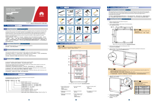
PDU8000 Smart Cooling PDF-TQuick GuidePDU8000 智能温控配电柜-T快速指南Issue: 01文档版本:01PDF Code: 02405418配电柜编码:02405418Date: 2019-6-25发布日期:2019-6-25The following figure shows the model naming conventions for an smart cooling PDC.智能温控配电柜的设备型号说明如下所示:To ensure safety of humans and the equipment, pay attention to the safety symbols on the equipment and all the safety instructions in this document. The "NOTE", "CAUTION", and "WARNING" marks in this document do not represent all the safety instructions. They are only supplements to the safety instructions. When operating Huawei equipment, in addition to following the general precautions in this document, follow the specific safety instructions given by Huawei. Huawei will not be liable for any consequences that are caused by the violation of safety regulations and design, production, and usage standards.为保障人身和设备安全,在安装、操作、维护设备时,请遵循设备上标识及手册中说明的所有安全注意事项。
RT-8000 控制器操作说明书(1)

ARGOJET系列AJC-50压电喷射阀控制器操作说明书目录第1章安全注意事项 (1)第2章产品规格 (2)第3章外形尺寸 (3)第4章面板介绍 (4)第5章机器操作 (5)第6章常见故障处理 (12)第1章安全注意事项在使用本产品前,请务必仔细阅读本手册,正确使用本产品,不得在超出该产品规格的情况下使用。
产品的所有者有责任确保对本产品的安装、操作和维护是由受过点胶控制器相关操作培训的专门人员完成,专门人员熟悉相关的安全规定和使用方法,并有能力执行该安全规定和使用方法。
为了防止造成任何人身伤害,对该产品的所有拆卸、维护操作,务必在确认设备切断电源,并且不会误触发的情况下进行,以免给您带来损害。
不安全的设备状态可能导致人员的受伤或财产的受损。
不遵守安全警示及采取安全预防措施将会对使用者人身造成严重伤害。
第2章产品规格AJC-50是一款高速压电喷射点胶阀控制器,可输出喷射阀的触发信号,提供阀的加热控制,并且可以实现和外部设备的通讯。
第3章外形尺寸图1 控制器正视图图2 控制器侧视图第4章 面板介绍外部通讯控制信号输加热器输出图4 后面板图5 液晶显示屏第5章机器操作5-1菜单操作本控制器有一个简单易用的人机界面,用户可以通过液晶屏及按键查看或设置各项控制器参数。
全部菜图6 菜单结构控制器在开机时进入主页面,用以显示各种状态信息。
在主页面下按ENTER进入菜单,用上下按键选择(选中项以反色显示),再按ENTER即可进入各设置页面,按ESC退到上一层页面。
5-2数值设置以设置Open Time(开阀时间)为例,说明如何设置一个数值。
其他的数值可参照同样步骤来设置。
1、按ENTER进入菜单,用上下键选中Valve Setting(开阀设置),再按ENTER进入。
2、用上下键选中Open Time(开阀时间)对应的数字(全部数字为反色显示),再按ENTER进入设置状态(最高位数字变为正色显示)。
3、用左右按键选择要修改的数位,然后用上下按键设置数值(0~9)。
xmt8000温控仪

XMT8000系列智能温度调节器一、概叙XMT*-8000系列升级版1与原XMT*-8000相比,新增功能及改变如下:●增加了手动指示灯“A-M”;●增加了通讯模块功能(Addr、bAud参数);●增加了运行状态设置参数(A-M);●增加了参数锁功能(LocK);●增加了现场参数定义(EP1~EP8)。
不同之处为:●自整定时闪动显示“At”字样(原AT灯亮);●信号出错时,闪动显示“orAL”字样(原显示HHHH)。
总之,升级后的XMT*-808系列仪表采用模块化结构,功能更强大,控制性能更优良,能广泛满足各种应用场合的需要。
注:仪表在使用前应对其输入、输出规格及功能要求来正确设置参数,只有配置好参数的仪表才能投入使用。
二、技术规格●输入规格(一台仪表即可兼容):热电偶:K、S、E、J热电阻:CU50、PT100●测量范围:K(0~1300℃)、S(0~1600℃)、E(0~800℃)、J(0~1000℃)CU50(-50~+150℃)、PT100(-200~+600℃)●测量精度:0.2级(+0.2%FS)●响应时间:≤0.5秒(设置数字滤波参数FILT=0时)●调节方式:位式调节方式(回差可调)人工智能调节,包含模糊逻辑PID调节及参数自整定功能的先进控制算法,控制精度可达±0.2℃。
●输出规格:模块化或非模块化直接订制输出功能参数:继电器触点开关输出(常开+常闭):250VAC/10A或30ASSR电压输出:12VDC/30mA(用于驱动SSR固态继电器)可控硅触发输出:可触发5-500A的双向可控硅;2个单向可控硅反向并联或可控硅功率模块线性电流输出:0~10 mA或4~20 mA可定义●报警功能:上限、下限、正偏差、负偏差等4种方式,最多可输出3路,有上电免除报警功能●电磁兼容:IEC61000-4-4(电快速瞬变脉冲群),+2KV/5KHZ;IEC61000-4-5(浪涌)4KV●隔离耐压:电源端、继电器触发及信号端相互之间≥2300V;相互隔离的弱电信号端之间≥600V●手动功能:自动/手动双向无扰动切换●电源:100-240VAC,-15%,+10%/50HZ;或24VDC/AC,-15%,+10%●电源消耗:≤5W●环境温度:0~50℃●面板尺寸:96×96mm、160×80mm、80×160mm、48×96mm、96×48mm、72×72mm、48×48mm●开口尺寸:92×92mm、152×76mm、76×152mm、45×92mm、92×45mm、68×68mm、45×45mm 三、型号意义XMT □8 □8 □(1)(2)(3) (4)(5)(1)外型尺寸标号:空格:160×80×150 开孔152×76;A:96×96×150 开孔92×92;D:72×72×110 开孔68×68;E:48×96×110 开孔44×92;F:96×48×110 开孔92×44;G:48×48×110 开孔45×45 (2)操作显示方式:‘8’:四键轻触开关设定,双排数字显示,模糊控制。
SCD8000 8100温度控制器用户手册说明书
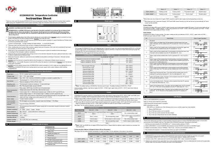
SCD8000/8100 Temperature ControllerInstruction SheetThank you very much for choosing SCD8000/8100 series temperature controller. Please read this instruction sheet carefully before using your SCD8000/8100 to ensure proper operation. Keep this instruction sheet handy for quick reference.!1Precaution!DANGER! CAUTION! ELECTRIC SHOCK!SCD8000/8100 is an OPEN-TYPE device and therefore should be installed in an enclosure free of airborne dust, humidity, electric shock and vibration. The enclosure should prevent non-maintenance staff from operating the device (e.g. key or specific tools are required for opening the enclosure) in case danger and damage on the device may occur .1. Prevent dust or metallic debris from falling into the device and cause malfunctions. DO NOT modify or uninstall the circuitboard of SCD8000/8100 without being permitted. DO NOT use empty terminals. 2. Keep away from high-voltage and high-frequency environment during the installation in case of interference. Prevent usingthe device in premises which contain:(a) dust or corrosive gas; (b) high humidity and high radiation; (c) shock and vibration. 3. The power has to be switched off when wiring or changing the temperature sensor.4. When installing the circuit board of the accessory, please make sure the power of the main unit is switched off and insertthe accessory into the correct slot on the main unit. 5. Make sure to use compensation wire which matches the thermocouple or platinum resistance when extending orconnecting the thermocouple or platinum resistance.6. Keep the wire as short as possible when wiring a sensor to the controller. Separate the power cable and load wire in orderto prevent interference and induced noise. 7. Make sure the power cables and signal device are installed correctly before switching on the power; otherwise seriousdamage may occur. 8. DO NOT touch the terminal or repair the device when the power is on; otherwise an electric shock may occur.9. Please wait for 1 minute after the power is switched off to allow the capacitor to discharge and DO NOT touch the internalwiring within this period. 10. DO NOT touch the internal terminal when SCD8000/8100 is either switched on or off in case you may damage the circuit. 11. Please place SCD8000/8100 with other heating objects (e.g. power supply) within proper distance while installingSCD8000/8100.2Power input DC 24V, isolated switching power supply Voltage range 90% ~ 110% rated voltagePower consumption Max. 10W + 3W × number of SCD2000 controllers connected in parallel (Max. 7) Thermocouple: K, J, T, E, N, R, S, B, L, U, TXK Input sensor Platinum resistance: Pt100, JPt100, Cu50Sampling cycle Thermocouple or platinum resistance: 1.0 second/all input Control method PID, PID programmable, manual, ON/OFFRelay output: SPST, Max. AC 250V load, 3A resistive load Voltage pulse output: DC 24V, Max. 40mA current outputCurrent output: DC 4 ~ 20mA output (resistive load < 500Ω); for OUT1 and OUT2 only Output accessories (optional)Analog voltage output: 0 ~ 10V (resistive load > 1,000Ω); for OUT1 and OUT2 onlyOutput functions Control output, alarm output or proportional output (proportional output is only applicable in themodel with linear voltage and current output for OUT1, OUT2) Alarm modes12 alarm modes availableCommunicationRS-485 digital communication; supports baud rate 2,400bps ~ 115,200bps Communication protocol Supports Modbus ASCII/RTUExtension port The extension port transmits 24V power supply and communication signals to extension module SCD2000.Vibration resistance 10 ~ 55Hz 10m/s 23 axes 10minsShock resistance Max. 300m/s 23 axes 6 directions, 3 times each Ambient temperature 0°C ~ +50°C Storage temperature -20°C ~ +65°C Operation altitude < 2,000mAmbient humidity 35% to 85% RH (non-condensing) Pollution degree23SCD8000/81001 I/O terminals2 Status LED 3Display and setup unit4 DIN rail clip5 Power input port6 RS-485 communication port 7Extension module fixing clip8 Extension port4 Panel Layout5InputThe standard SCD8000/8100 main unit is attached with 4 channels of inputs. You can purchase additional SCD-4T or SCD-4Rto expand the number of input channels. SCD8000/8100 supports maximum 8 channels of inputs which belong to group INA and group INB. Each group possesses 4 input channels. SCD8000/8100 series supports the following input sensors:Input Sensor TypeRegister ValueRangeFor SCD8100 / SCD-4RTemperature measurement resistance (Cu50)13 -50 ~ 150°C Platinum resistance (Pt100)12 -200 ~ 600°C Platinum resistance (JPt100) 11-20 ~ 400°C For SCD8000 / SCD-4TThermocouple TXK type 10-200 ~ 800°C Thermocouple U type 9 -200 ~ 500°C Thermocouple L type 8 -200 ~ 850°C Thermocouple B type 7 100 ~ 1,800°C Thermocouple S type 6 0 ~ 1,700°C Thermocouple R type 5 0 ~ 1,700°C Thermocouple N type 4 -200 ~ 1,300°C Thermocouple E type 3 0 ~ 600°C Thermocouple T type 2 -200 ~ 400°C Thermocouple J type 1 -100 ~ 1,200°C Thermocouple K type-200 ~ 1,300°CNote: The default setting in SCD8000 is “thermocouple K type”. The default setting in SCD8100 is “Pt100".Communication address: Input sensor types at H10A0 ~ H10A7; input upper limits at H1010 ~ H1017; input lower limits atH1018 ~ H101F.6OutputSCD8000/8100 supports maximum 16 channels of outputs, belonging to output groups OUT1, OUT2, SUB1 and SUB2, each group with 4 channels. See the explanations below for how input channels correspond to output groups.Without group INB (4 channels of input): Every channel corresponds to 2 groups of output and 2 groups of alarms. OUT1 and SUB1 are for control output, and OUT1 can be used for proportional output. OUT2 and SUB2 are fixed for alarm output. With group INB (8 channels of input): Every channel is paired with 2 groups of outputs. OUT1 and OUT2 are used for control output or proportional output of CH1 ~ CH8. SUB1 and SUB2 are used for control output or alarm output. See Table 1 for the relations between input and output.4 channels of input 8 channels of inputOutput GroupINA (CH1 ~ CH4)INA (CH1 ~ CH4)INB (CH5 ~ CH8) OUT1 Main control output or proportional output Main control output or proportionaloutputNo corresponding output OUT2 Alarm 1 output No corresponding output Main control output or proportionaloutputSUB1 Control output Control output or alarm output No corresponding output SUB2Alarm 2 outputNo corresponding output Control output or alarm outputTable 1Note: SUB1 and SUB2 do not support SCD-46 and SCD-45. Please install the optional output modules you purchase intothe correct slot.Communication Address of Output & How to Set up Parameters:See Table 2 for the communication addresses of output and Table 3 for the definition of the value in the address. INAINBCH1 CH2 CH3 CH4 CH5 CH6 CH7 CH8 OUT1, OUT2 H10A8 H10A9 H10AA H10AB H10AC H10AD H10AE H10AF SUB1, SUB2H10B0H10B1H10B2H10B3H10B4H10B5H10B6H10B7Table 2Value = 0Value = 1 Value = 2 Value = 3 OUT1, OUT2** Heating control Cooling control Proportional output Disable output SUB1, SUB2**Heating controlCooling controlAlarm output*Disable outputTable 3*When there are only 4 channels of inputs, SUB1 cannot be used for alarm output but heating/cooling control only.**When there are only 4 channels of inputs, OUT2 and SUB2 cannot be set up by the user but set up automatically as "alarmoutput” by the controller. Control Output:SCD8000/8100 offers PID control, ON/OFF control, manual control and programmable PID control. Control output methods are set at address H10B8 ~ H10BF (default = 0: PID), PID parameters at H1028 ~ H105F, ON/OFF parameters at H1058 ~ H106F, and manual control parameters at H1070 ~ H107F. Alarm Output:SCD8000/8100 offers 12 alarm modes. The alarm modes are set up at address H10C0 ~ H10C7, upper limits at H1080 ~ H1087 and lower limits at H1088 ~ H108F.7LED DisplayPWR: On B SCD8000/8100 is powered. RUN: On B Any of the channel is executing. COM: Flashing B Communication in progress ERR: Indicating errors (red)ERR LED is on indicates one of the following errors occur, and the output has to be disabled. 1. Memory EEPROM error.2. Any of the input points is not connected.3. Any of the input points exceeds the setup range.4. Any of the input temperatures has not been stabilized.8Synchronous Communication Protocol & Auto ID SetupThis function allows the auto setup of communication protocol in extension module SCD2000 following the communicationprotocol set in the SCD8000 main unit. The station IDs of SCD2000 decrease. See below for the steps. 1. Set the auto communication ID of SCD8000 as “1” (communication address: H10F8).2. Switch off SCD8000. Connect SCD8000 with extension module SCD2000 and switch on SCD8000 again.3. Default communication protocol: 9,600bps, 7 bits, Even, 1 stop bit, communication address = 01.4. This function will consume 3 ~ 5 seconds more when you switch on SCD8000.9RS-485 Communication1. SCD8000/8100 supports baud rates 2,400/4,800/9,600/19,200/38,400/57,600/115,200 bps and does not supportcommunication format 7, N, 1/8, E, 2/8, O, 2. Communication protocol = Modbus ASCII or RTU. 2. Function codes: H03 = read maximum 8 words in the register; H06 = write 1 word into the register.3. Address and contents: Every parameter has 2 communication addresses. One is numbered by the function of the parameter, and the other is by the order of channel (as shown in the table below).Content Explanation CH1 CH2 CH3 CH4 CH5 CH6 CH7 CH8 Presenttemperature value/input error code Unit; 0.1See Table 5H1000(H1100)H1001(H1200)H1002(H1300)H1003(H1400)H1004(H1500)H1005(H1600)H1006(H1700)H1007(H1800)Set temperature value Unit: 0.1H1008(H1101)H1009(H1201)H100A(H1301)H100B(H1401)H100C(H1501)H100D(H1601)H100E(H1701)H100F(H1801)Max. temperature value Disabled when higherthan default valueH1010(H1102)H1011(H1202)H1012(H1302)H1013(H1402)H1014(H1502)H1015(H1602)H1016(H1702)H1017(H1802)Min. temperature value Disabled when lowerthan default valueH1018(H1103)H1019(H1203)H101A(H1303)H101B(H1403)H101C(H1503)H101D(H1603)H101E(H1703)H101F(H1803)Error temperature value -999 ~ +999Unit: 0.1°CH1020(H1104)H1021(H1204)H1022(H1304)H1023(H1404)H1024(H1504)H1025(H1604)H1026(H1704)H1027(H1804)Proportional band value (Pb) 0 ~ 9,999Unit: 0.1H1028(H1105)H1029(H1205)H102A(H1305)H102B(H1405)H102C(H1505)H102D(H1605)H102E(H1705)H102F(H1805)Ti value 0 ~ 9,999H1030(H1106)H1031(H1206)H1032(H1306)H1033(H1406)H1034(H1506)H1035(H1606)H1036(H1706)H1037(H1806)Td value 0 ~ 9,999H1038(H1107)H1039(H1207)H103A(H1307)H103B(H1407)H103C(H1507)H103D(H1607)H103E(H1707)H103F(H1807)Integration default 0.0 ~ 100.0%Unit: 0.1%H1040(H1108)H1041(H1208)H1042(H1308)H1043(H1408)H1044(H1508)H1045(H1608)H1046(H1708)H1010(H1808)Proportional control offset error value, when Ti = 0 0.0 ~ 100.0%Unit: 0.1%H1048(H1109)H1049(H1209)H104A(H1309)H104B(H1409)H104C(H1509)H104D(H1609)H104E(H1709)H104F(H1809)Proportional band coefficient of output 1 and output 2 0.01 ~ 99.99Unit: 0.01H1050(H110A)H1051(H120A)H1052(H130A)H1053(H140A)H1054(H150A)H1055(H160A)H1056(H170A)H1057(H180A)Dead band ofcontrol output 1 & output 2. -99.9 ~ 999.9H1058(H110B)H1059(H120B)H105A(H130B)H105B(H140B)H105C(H150B)H105D(H160B)H105E(H170B)H105F(H180B)Hysteresis for output 1 0 ~ 9,999Unit: 0.1%H1060(H110C)H1061(H120C)H1062(H130C)H1063(H140C)H1064(H150C)H1065(H160C)H1066(H170C)H1067(H180C)Hysteresis for output 2 0 ~ 9,999Unit: 0.1%H1068(H110D)H1069(H120D)H106A(H130D)H106B(H140D)H106C(H150D)H106D(H160D)H106E(H170D)H106F(H180D)Read/write output 1 value Unit: 0.1 %H1070(H110E)H1071(H120E)H1072(H130E)H1073(H140E)H1074(H150E)H1075(H160E)H1076(H170E)H1077(H180E)Read/write output 2 value Unit: 0.1 %H1078(H110F)H1079(H120F)H107A(H130F)H107B(H140F)H107C(H150F)H107D(H160F)H107E(H170F)H107F(H180F)Upper limit for alarm output Alarm enabledwhen temperatureexceeds upper limitH1080(H1110)H1081(1210)H1082(H1310)H1083(H1410)H1084(H1510)H1085(H1610)H1086(H1710)H1087(H1810)Lower limit for alarm output Alarm enabledwhen temperaturefalls below lowerlimitH1088(H1111)H1089(H1211)H108A(H1311)H108B(H1411)H108C(H1511)H108D(H1611)H108E(H1711)H108F(H1811)Tuning for upper limit of analog output Current (4 ~ 20mA)or voltage outputtuningH1090(H1112)H1091(H1212)H1092(H1312)H1093(H1412)H1094(H1512)H1095(H1612)H1096(H1712)H1097(H1812)Tuning for lower limit of analog output Current (4 ~ 20mA)or voltage outputtuningH1098(H1113)H1099(H1213)H109A(H1313)H109B(H1413)H109C(H1513)H109D(H1613)H109E(H1713)H109F(H1813)Input sensor type See “Input” section H10A0(H1114)H10A1(H1214)H10A2(H1314)H10A3(H1414)H10A4(H1514)H10A5(H1614)H10A6(H1714)H10A7(H1814)Output function for output 1 0: heating1: cooling2: proportionaloutputH10A8(H1115)H10A9(H1215)H10AA(H1315)H10AB(H1415)H10AC(H1515)H10AD(H1615)H10AE(H1715)H10AF(H1815)Output function for output 2 0: heating (default)1: cooling2: alarmH10B0(H1116)H10B1(H1216)H10B2(H1316)H10B3(H1416)H10B4(H1516)H10B5(H1616)H10B6(H1716)H10B7(H1816)Control method 0: PID1: ON-OFF2: manual3: PIDprogrammableH10B8(H1117)H10B9(H1217)H10BA(H1317)H10BB(H1417)H10BC(H1517)H10BD(H1617)H10BE(H1717)H10BF(H1817)Alarm 1 output mode See “Alarm Output”sectionH10C0(H1118)H10C1(H1218)H10C2(H1318)H10C3(H1418)H10C4(H1518)H10C5(H1618)H10C6(H1718)H10C7(H1818)Alarm 2 output mode See “Alarm Output”sectionH10C4(H1518)H10C5(H1618)H10C6(H1718)H10C7(H1818)Heating/cooling cycle for output 1 1 ~ 99 seconds0 = 0.5 secondH10C8(H1119)H10C9(H1219)H10CA(H1319)H10CB(H1419)H10CC(H1519)H10CD(H1619)H10CE(H1719)H10CF(H1819)Heating/cooling cycle for output 2 1 ~ 99 seconds0 = 0.5 secondH10D0(H111A)H10D1(H121A)H10D2(H131A)H10D3(H141A)H10D4(H151A)H10D5(H161A)H10D6(H171A)H10D7(H181A)Run/Stop the control 0: stop1: executing2: program stops3: program pausesH10D8(H111B)H10D9(H121B)H10DA(H131B)H10DB(H141B)H10DC(H151B)H10DD(H161B)H10DE(H171B)H10DF(H181B)Status of PID auto-tuning 0: stop1: executingH10E0(H111C)H10E1(H121C)H10E2(H131C)H10E3(H141C)H10E4(H151C)H10E5(H161C)H10E6(H171C)H10E7(H181C)Positive/negative proportional 0: positive1: negative (slope)H10E8(H111D)H10E9(H121D)H10EA(H131D)H10EB(H141D)H10EC(H151D)H10ED(H161D)H10EE(H171D)H10EF(H181D)Content Explanation CH1 CH2 CH3 CH4 CH5 CH6 CH7 CH8outputOther statuses Other statusesH10F0TemperatureunitH10F1Open specialfunction(H1234)H10F2Return todefault(H1357)H10F3ReservedH10F4ReservedH10F5ReservedH10F6ReservedH10F7ReservedCommunicationspecificationsSee Table 4H10F8Auto IDsetupH10F9ReservedH10FABaud rateH10FBASCII = 0RTU = 1H10FC8 bits=07 bits=1H10FD2 stop=01 stop=1H10FEParityH10FFAddress1 ~ 247Communication Parameter Setting:Content 0 1 2 3 4 5 6Baud rate 2,400bps 4,800bps 9,600bps 19,200bps 38,400bps 57,600bps 115,200bpsParity bit None (N) Even (E) Odd (O)Table 4Error Codes:The error codes can be read from address H1000 ~ H1007. When the input operation is in normal status, H1000 ~ H1007 arefor input values. When input error occurs (except for stable status and input exceeding the range), SCD8000/8100 will readerror codes in H8001 ~ H8002.H1000 ErrordescriptionH8001 EEPROM cannot be written in.H8002 Input sensor is not connected.H8003 Group INB is not connected.Table 5Analog output current tuning scale: 1μA/scaleAnalog output voltage tuning scale: 1mV/scaleReturning to Default Value: Write H1234 into address H10F1 and H1357 into address H10F2. Restart SCD8000/8100.Programmable Communication Parameter Setting:Content Explanation CH1 CH2 CH3 CH4 CH5 CH6 CH7 CH8Read remaining time of the step Unit: sec H111E H121E H131E H141E H151E H161EH171EH181ERead remaining time of the step Unit: min H111F H121F H131F H141F H151F H161F H171F H181FRead the NO. of the currentpattern0 ~ 7 H1120 H1220 H1320 H1420 H1520 H1620 H1720 H1820Read the NO. of the current step 0 ~ 7 H1121 H1221 H1321 H1421 H1521 H1621 H1721 H1821NO. of start pattern 0 ~ 7 H1122 H1222 H1322 H1422 H1522 H1622 H1722 H1822NO. of start step 0 ~ 7 H1123 H1223 H1323 H1423 H1523 H1623 H1723 H1823Programmable Parameter Setting:Content ExplanationPatternPattern1Pattern2Pattern3Pattern4Pattern5Pattern6Pattern7Max. number ofsteps in the pattern0 ~ 7 = N: The patternexecutes from step 0 toN.H2068 H2069 H206A H206B H206C H206D H206E H206FNumber of cycles ofpattern 0 ~ 7execution0 ~ 199: The patternhas been executed for 1~ 200 timesH2070 H2071 H2072 H2073 H2074 H2075 H2076 H2077NO. of current linkpattern0 ~ 8: 8 refers to end ofprogram; 0 ~ 7 refer tothe NO. of next patternH2078 H2079 H207A H207B H207C H207D H207E H207FAddress Default Content Explanation2000H ~ 203FH 0Target temperatures for pattern 0 ~ 7Pattern 0: 2000H ~ 2007HUnit: 0.1°C2080H ~ 20BFH 0Execution time for pattern 0 ~ 7Pattern 0: 2080H ~ 2087HTime: 0 ~ 900 (Unit: 1 min)4. Communication format: H03 = read bit data; H06 = write bit dataASCII Mode:Read Command Read Response Message Write Command Write Response MessageStart word ’:’ Start word ’:’ Start word ’:’ Start word ’:’Machine address 1 ‘0’ Machine address 1 ‘0’ Machine address 1 ‘0’ Machine address 1 ‘0’Machine address 0 ‘1’ Machine address 0 ‘1’ Machine address 0 ‘1’ Machine address 0 ‘1’Command 1 ‘0’ Command 1 ‘0’ Command 1 ‘0’ Command 1 ‘0’Command 0 ‘3’ Command 0 ‘3’ Command 0 ‘6’ Command 0 ‘6’‘1’ ‘0’ ‘1’ ‘1’‘0’Length of responsedata (byte) ‘4’ ‘0’ ‘0’‘0’ ‘0’ ‘0’ ‘0’Read start address ofdata/bit‘0’ ‘1’Data address‘1’Data address‘1’‘0’ ‘F’ ‘0’ ‘0’Read length of data/bit(word/bit) ‘0’Data content in H1000‘4’Write data content‘3’Write data content‘3’Read Command Read Response Message Write Command Write Response Message‘0’ ‘0’ ‘E’ ‘E’‘2’ ‘0’ ‘8’ ‘8’LRC1 check ‘E’ ‘0’ LRC1 check ‘F’ LRC1 check ‘F’LRC0 check ‘A’Data content in H1001‘0’ LRC0 check ‘D’ LRC0 check ‘D’End word 1 CR LRC1 check ‘0’ End word 1 CR End word 1 CREnd word 0 LF LRC0 check ‘3’ End word 0 LF End word 0 LFEndword1CREndwordLFLRC Check:Sum up the contents from “machine address” to “data content”, e.g. H01 + H03 + H10 + H00 + H00 + H02 = H16. Obtain2’scomplement H EA.RTU Mode:Read Command Read Response Message Write Command Write Response MessageMachine address H01 Machine address H01 Machineaddress H01 Machineaddress H01Command H03 Command H03 Command H06 Command H06H10 H10 H10Read start address ofdata H00Length of responsedata (byte)H04 Write data addressH01Write data addressH01H00 H01 H03 H03Read length of data(bit/word) H02Data content 1HF4Write data contentH20Write data contentH20CRC low byte HC0 H03 CRClowbyte HDD CRC low byte HDDCRC high byte HCBData content 2H20 CRC high byte HE2 CRC high byte HE2CRClowbyteHBBCRC high byte H15CRC (Cyclical Redundancy Check) is obtained by the following steps:unsigned int reg_crc = 0xffff;i = 0;while (length--){ reg_crc ^=RTUData[i];i ++;for (j = 0; j < 8; j++){ if (reg_crc & 0x01) reg_crc =(reg_crc >> 1) ^ 0xA001;else reg_crc = reg_crc >> 1;}}return(reg_crc);Software for Setting up Communication on PC: Download the free software on Dwyer’s website.10Connect maximum 7 SCD2000 controllers to SCD8000 by using DIN rail.。
- 1、下载文档前请自行甄别文档内容的完整性,平台不提供额外的编辑、内容补充、找答案等附加服务。
- 2、"仅部分预览"的文档,不可在线预览部分如存在完整性等问题,可反馈申请退款(可完整预览的文档不适用该条件!)。
- 3、如文档侵犯您的权益,请联系客服反馈,我们会尽快为您处理(人工客服工作时间:9:00-18:30)。
T8000系列触摸屏温控器
应用
T8200…JS0/R0触摸屏温控器是为控制商业、工业和民用项目中制热、制冷及空调所设计的。
其典型应用包括控制风机盘管、空调末端和制热制冷设备。
作为系统的一部分,其控制一个二通或三通阀门以及一个多级风速的风机。
T8200…JF0触摸屏温控器适用于中央空调和地板采暖二合一的系统中,夏季开启中央空调,利用现场温度来控制风机盘管的启停,使用户得到舒适的环境。
在冬季既可以通空调机实现快速风暖制热,也可驱动地暖系统,享受地暖的舒适宁静。
T8000温控器采用容式触摸技术,使操作更加方便。
采用微电脑控制技术,大屏幕液晶显示,液晶显示状态有:工作状态(制冷、制热、通风)、风机风速、室内温度、设置温度
等。
按键有:电源开关()、模式转换键(M)、风速选择键 ()
和温度设置键(∧和∨)。
特点和优势T8200…JS0/R0
触摸屏温控器
功能及选型
产品概述
T8000触摸屏温控器有七种基本型号,满足所有类型风机盘管以及空调采暖二合一系统独立控制应用。
有2管制冷暖型、4管制冷暖型和空调+地板采暖,在风机盘管和空调+采暖中控制2线阀门。
内置高精度NTC传感器使受控区域温度控制精确和舒服。
T8000温控器有12小时定时功能,用户可根据自己的需要安排开启或关闭定时功能。
88x88mm尺寸可方便安装在75x75x35mm标准墙装盒上。
适合任何室内装潢。
T8200-TB20-9JS0型号
型号T8200-TB20-9JS0,AC220V电压,LCD显示(有背光)风机盘管温控器是为2管制冷暖风机盘管设计的,用于2线电动阀门控制,有系统开关按钮,用户可关闭T8000温控器,切断风机输出电源(切断阀门执行器输出电源)。
仅需按风速按钮,用户可选择自动-高-中-低风速。
所有风机继电器输出具有标准最大5Amp.(阻性)工作电流。
有干触点有无人模式使控制更为舒适且更为节能。
T8200-TB20-9JR0型号
型号T8200-TB20-9JR0,AC220V电压,LCD显示(有背光)风机盘管温控器是为2管制冷暖风机盘管设计的,用于2线电动阀门控制,有系统开关按钮,用户可关闭T8000温控器,切断风机输出电源(切断阀门执行器输出电源)。
仅需按风速按钮,用户可选择自动-高-中-低风速。
所有风机继电器输出具有标准最大5Amp.(阻性)工作电流。
带外置温度传感器。
T8200-TF20-9JS0型号
型号T8200-TF20-9JS0,AC220V电压,LCD显示(有背光)风机盘管温控器是为4管制冷暖风机盘管设计的,用于2线电动阀门控制,有系统开关按钮,用户可关闭T8000温控器,切断风机输出电源(切断阀门执行器输出电源)。
仅需按风速按钮,用户可选择自动-高-中-低风速。
所有风机继电器输出具有标准最大5Amp.(阻性)工作电流。
有干触点有无人模式使控制更为舒适且更为节能。
T8200-TF20-9JR0型号
型号T8200-TF20-9JR0,AC220V电压,LCD显示(有背光)风机盘管温控器是为4管制冷暖风机盘管设计的,用于2线电动阀门控制,有系统开关按钮,用户可关闭T8000温控器,切断风机输出电源(切断阀门执行器输出电源)。
仅需按风速按钮,用户可选择自动-高-中-低风速。
所有风机继电器输出具有标准最大5Amp.(阻性)工作电流。
带外置温度传感器。
T8200-TB21-9JS0型号
型号T8200-TB21-9JS0,AC24V电压,LCD显示(有背光)风机盘管温控器是为2管制冷暖风机盘管设计的,用于比例积分阀门(0-10V)控制,有系统开关按钮,用户可关闭T8000温控器,切断风机输出电源(切断阀门执行器输出电源)。
仅需按风速按钮,用户可选择自动-高-中-低风速。
所有风机继电器输出具有标准最大5Amp.(阻性)工作电流。
有干触点有无人模式使控制更为舒适且更为节能。
T8200-TB21-9JR0型号
型号T8200-TB21-9JR0,AC24V电压,LCD显示(有背光)风机盘管温控器是为2管制冷暖风机盘管设计的,用于比例积分阀门(0-10V)控制,有系统开关按钮,用户可关闭T8000温控器,切断风机输出电源(切断阀门执行器输出电源)。
仅需按风速按钮,用户可选择自动-高-中-低风速。
所有风机继电器输出具有标准最大5Amp.(阻性)工作电流。
带外置温度传感器。
T8200-TB20-9JF0型号
型号T8200-TB20-9JF0,AC220V电压,LCD显示(有背光)空调+地板采暖温控器是为2管制冷暖风机盘管和水采暖系统设计的,用于2线电动阀门控制,有系统开关按钮,用户可关闭T8000温控器,切断风机输出电源(切断阀门执行器输出电源)和采暖阀门电源。
仅需按风速按钮,用户可选择自动-高-中-低风速。
所有风机和阀门继电器输出具有标准最大5Amp.(阻性)工作电流。
重要:
T8000系列风机盘管或采暖温控器仅作控制使用。
温控器失灵或故障可能伤及他人或损害受控设备的财物或其它财物,系统必须设计另外的预防措施,使之与其它监控、报警、安全和限制控制在同一系统中,从而预警和保护T8000系列温控器的失灵或故障。
尺寸
安装
T8000系列温控器设计为标准75 x75 x 35mm 墙装接线盒安装
T8200-TB21.../T8200-TF.../T8200-TB20-9JF0
T8200-TB20-9JS0/JR0
235
* 请安装前移除绝缘片
火线 AC85~260V 50/60Hz L 火线
AC85~260V 50/60Hz
火线 火线 火线
接线图
T8200-TB20-9JS0
T8200-TB21-9JSO
T8200-TB20-9JR0
T8200-TB21-9JRO
T8200-TB20-9JF0
* 连接完成后,On/Off 开关并不是电源的开关,而是液晶LCD 和其它功能键的开关。
技术参数
订货信息
订货更换T8000系列温控器,请就近联系Johnson Controls ®办事处。
从选型表中确定想要的产品型号。
重要:
温控器供电电源必须有过载保护。
没有过载保护可能会毁坏温控器。