RPLIDAR A2 M6 360度激光扫描测距雷达简介与规格书
什么是LiDAR激光雷达

1 什么是LiDARLiDAR,是Light Detection and Ranging的缩写,常用作代表激光雷达。
LiDAR是一种传感技术,可发射低功率,人眼安全的激光进行脉冲测量,并测量激光完成传感器与目标之间往返所需的时间。
所得的聚合数据用于生成3D点云图像,同时提供空间位置和深度信息以识别,分类和跟踪运动对象。
LiDAR工作原理:LiDAR的工作原理是检测并测量返回传感器接收器的光。
一些目标比其他目标反射的光线更好,这使它们更容易可靠地检测和测量到传感器的最大范围。
比如,黑色表面善于吸收更多光,而白色表面能够反射更多的光。
这样一来,与目标主题颜色相对较暗的目标相比,相对颜色较亮的目标更容易在更长的距离上受到可靠地检测或测量。
对于窗户等像镜子一样的目标在检测和测量方面颇具挑战性,因为与在多个方向上分散光的漫射目标不同,类似镜子的物体只能反射很小的聚焦光束,而不会直接反射到传感器的接收器中。
同时,诸如路标和车牌之类的可反光目标将高百分比的光返回接收器,并且是LiDAR传感器的良好目标。
由于存在这些差异,LiDAR传感器的实际性能和最大有效范围可能会根据目标的表面反射率而有所不同。
1.1点云点云是在同一空间参考系下表达目标空间分布和目标表面特性的海量点集合,在获取物体表面每个采样点的空间坐标后,得到的诸多特征点的集合,称之为“点云”(Point Cloud)。
点云是由3D点数据组成的大型数据集,由激光测量原理得到。
车载激光雷达产生的点云包含来自周围环境的原始数据,这些原始数据是从移动物体(例如车辆和人)以及静止物体(例如建筑物,树木和其他永久性结构)扫描而来的。
然后可以通过软件系统转换包含数据点的点云,以创建给定区域的基于LiDAR的3D图像。
激光测量得到的点云内容包括三维坐标(XYZ)和激光反射强度(Intensity),强度信息与目标的表面材质、粗糙度、入射角方向,以及仪器的发射能量,激光波长有关参数等。
Slamtec RPLIDAR A2 360度激光雷达扫描仪产品说明
RPLIDAR A2 2016-10-28 rev.1.0Low Cost 360 Degree Laser Range ScannerIntroduction and DatasheetModel: A2M5A2M6OPTMAG 4KCONTENTS (1)INTRODUCTION (3)S YSTEM CONNECTION (4)M ECHANISM (5)S AFETY AND S COPE (6)D ATA O UTPUT (6)H IGH S PEED S AMPLING P ROTOCOL AND C OMPATIBILITY (7)A PPLICATION S CENARIOS (8)SPECIFICATION (9)M EASUREMENT P ERFORMANCE (9)L ASER P OWER S PECIFICATION (9)O PTICAL W INDOW (10)C OORDINATE S YSTEM D EFINITION OF S CANNING D ATA (10)C OMMUNICATION INTERFACE (11)MISC (14)SELF-PROTECTION AND STATUS DETECTION (15)SDK AND SUPPORT (16)MECHANICAL DIMENSIONS (17)REVISION HISTORY (18)APPENDIX (19)I MAGE AND T ABLE I NDEX (19)The RPLIDAR A2 is the next generation low cost 360 degree 2D laser scanner (LIDAR) solution developed by SLAMTEC. It can take up to 4000 samples of laser ranging per second with high rotation speed. And equipped with SLAMTEC patented OPTMAG technology, it breakouts the life limitation of traditional LIDAR system so as to work stably for a long time.RPLIDAR A2M5/A2M6 is the enhanced version of 2D laser range scanner(LIDAR). The system can perform 2D 360-degree scan within a 16-meter range. The generated 2D point cloud data can be used in mapping, localization and object/environment modeling.The typical scanning frequency of the RPLIDAR A2 is 10hz (600rpm). Under this condition, the angular resolution will be 0.9°. And the actual scanning frequency can be freely adjusted within the 5-15hz range according to the requirements of users.The RPLIDAR A2 adopts the low cost laser triangulation measurement system developed by SLAMTEC, which makes the RPLIDAR A2 has excellent performance in all kinds of indoor environment and outdoor environment without direct sunlight exposure. Meanwhile, before leaving the factory, every RPLIDAR A2 haspassed the strict testing to ensure the laser output power meet the standards of FDA Class I.System connectionThe RPLIDAR A2 consists of a range scanner core and the mechanical powering part which makes the core rotate at a high speed. When it functions normally, the scanner will rotate and scan clockwise. And users can get the range scan data via the communication interface of the RPLIDAR and control the start, stop and rotating speed of the rotate motor via PWM.Range Scanner CoreCommunication andPower Interface MechanicalPowering PartFigure 1-1 RPLIDAR System CompositionThe RPLIDAR A2 comes with a rotation speed detection and adaptive system. The system will adjust the angular resolution automatically according to the actual rotating speed. And there is no need to provide complicated power system for RPLIDAR. In this way, the simple power supply schema saves the BOM cost. If the actual speed of the RPLIDAR is required, the host system can get the related data via communication interface.The detailed specification about power and communication interface can be found in the following sections.MechanismThe RPLIDAR A2 is based on laser triangulation ranging principle and adopts the high-speed vision acquisition and processing hardware developed by SLAMTEC. The system ranges more than 4000 times per second.dFigure 1-2 The RPLIDAR Working SchematicDuring every ranging process, the RPLIDAR emits modulated infrared laser signal and the laser signal is then reflected by the object to be detected. The returning signal is then sampled by vision acquisition system in RPLIDAR and the DSP embedded in RPLIDAR starts processing the sample data and outputs distance value and angle value between object and RPLIDAR via communication interface.When drove by the motor system, the range scanner core will rotate clockwise and perform the 360-degree scan for the current environment.Figure 1-3 The Obtained Environment Map from RPLIDAR ScanningSafety and ScopeThe RPLIDAR A2 system uses a low power infrared laser as its light source, and drives it by using modulated pulse. The laser emits light in a very short time frame which can ensure its safety to human and pets, and it reaches Class I laser safety standard.The modulated laser can effectively avoid the interference from ambient light and sunlight during ranging scanning process, which makes RPLIDAR work excellent in all kinds of indoor environment and outdoor environment without sunlight.Data OutputDuring the working process, the RPLIDAR will output the sampling data via the communication interface. And each sample point data contains the information in the following table. If you need detailed data format and communication protocol, please contact SLAMTEC.*Note :The LIDAR scan image is not directly relative to the environment showed here. Illustrative purpose only.Class IFigure 1-4 The RPLIDAR Sample Point Data InformationFigure 1-5 The RPLIDAR Sample Point Data FramesThe RPLIDAR outputs sampling data continuously and it contains the sample point data frames in the above figure. Host systems can configure output format and stop RPLIDAR by sending stop command. For detailed operations please contact SLAMTEC.High Speed Sampling Protocol and CompatibilityThe RPLIDAR A2 adopts the newly extended high speed sampling protocol for outputting the 4000 times per second laser range scan data. Users are required to update the matched SDK or modify the original driver and use the new protocol to use the 4000 times per second mode of RPLIDAR A2. Please check the related protocol documents for details.The RPLIDAR A2 is compatible with all the communication protocols of previous versions. Users can directly replace the previous RPLIDAR with RPLIDAR A2 and use it in the original system. But in this scenario, the RPLIDAR A2 will work in compatible mode and the system will take range 2000 times per second.Data TypeUnitDescriptionDistance mm Current measured distance value between the rotating core of the RPLIDAR and the sampling point Heading degree Current heading angle of the measurement Start Flag (Bool) Flag of a new scanChecksumThe Checksum of RPLIDAR return data…(d ሾn −1ሿ,θሾn −1ሿ)(d ሾn ሿ,θሾn ሿ) (d ሾ0ሿ,θሾ0ሿ) (d ሾ1ሿ,θሾ1ሿ)…Start FlagA new scanApplication ScenariosThe RPLIDAR can be used in the following application scenarios:o General robot navigation and localizationo Environment scanning and 3D re-modelingo Service robot or industrial robot working for long hourso Home service /cleaning robot navigation and localization o General simultaneous localization and mapping (SLAM)o Smart toy’s localization and obstacle avoidanceMeasurement Performance●For Model A2M5/A2M6 OnlyFigure 2-1 RPLIDAR PerformanceNote: the triangulation range system resolution changes along with distance. Laser Power SpecificationFigure 2-2 RPLIDAR Optical SpecificationNote: the laser power listed above is the peak power and the actual average power is much lower than the value.Optical WindowTo make the RPLIDAR A2 working normally, please ensure proper space to be left for its emitting and receiving laser lights when designing the host system. The obscuring of the host system for the ranging window will impact the performance and resolution of RPLIDAR A2. If you need cover the RPLIDAR A2 with translucent materials or have other special needs, please contact SLAMTEC about the feasibility.Optical WindowFigure 2-3 RPLIDAR Optical WindowYou can check the Mechanical Dimensions chapter for detailed window dimensions.Coordinate System Definition of Scanning DataThe RPLIDAR A2 adopts coordinate system of the left hand. The dead ahead of the sensors is the x axis of the coordinate system; the origin is the rotating center of the range scanner core. The rotation angle increases as rotating clockwise. The detailed definition is shown in the following figure:Figure 2-4 RPLIDAR Scanning Data Coordinate System DefinitionCommunication interfaceThe RPLIDAR A2 uses separate 5V DC power for powering the range scanner core and the motor system. And the standard RPLIDAR A2 uses XH2.54-5P male socket. Detailed interface definition is shown in the following figure:Figure 2-5 RPLIDAR Power Interface Definitionθ ሾ0,360)Interface LeadRedXH2.54-5PVCCTXRXGND MOTOCTLFigure 2-6 RPLIDAR External Interface Signal DefinitionPower Supply InterfaceRPLIDAR A2 takes the only external power to power the range scanner core and the motor system which make the core rotate. To make the RPLIDAR A2 work normally, the host system needs to ensure the output of the power and meet its requirements of the power supply ripple.Figure 2-7 RPLIDAR Power Supply SpecificationData communication interfaceThe RPLIDAR A2 takes the 3.3V-TTL serial port (UART) as the communication interface. The table below shows the transmission speed and the protocol standard.Figure 2-8 RPLIDAR Serial Port Interface SpecificationsNote: the RX input signal of A2M5/A2M6 is current control type. In order to ensure the reliable signal identification inside the system, the actual control node voltage of this pin will not be lower than 1.6v. Scanner Motor ControlThe RPLIDAR A2 is embedded with a motor driver which has speed tuning feature. Users can control the start, the stop and the rotating speed for the motor via MOTOCTL in the interface. MOTOCTL can be supplied using PWM signal with special frequency and duty cycle, and in this mode, the rotating speed is decided by the duty cycle of the input MOTOCTL PWM Signal.The following table describes the requirement for the input PWM signal of MOTOCTL:Figure 2-9 RPLIDA Specification for PWM Signal of MOTOCTLNote: the typical value is tested when the scanner rotating frequency is 10Hz. With the same rotating speed, the PWM duty cycle of every RILIDAR A2 may vary slightly. If a precise rotating speed is required, users can perform a closed-loop control.If the host system only need to control the start and stop of the motor, please use the direct current signal in high level and low level to drive MOTOCTL. Under this condition, when the MOTOCTL is the low level signal, the RPLIDAR A2 will stop rotating and scanning; when the MOTOCTL is the high level signal, the RPLIDAR A2 will rotated at the highest speed.MISCFor Model A2M5/A2M6 OnlyFigure 2-10 RPLIDAR MISC SpecificationTo ensure the laser of RPLIDAR always working in the safety range (<3mW) and avoid any other damage caused by device, the RPLIDAR comes with laser power detection and sensor healthy check feature. It will shut down the laser and stop working automatically when any of the following errors has been detected.o Laser transmit power exceeds limited valueo Laser cannot power on normallyo Scan speed of Laser scanner system is unstableo Scan speed of Laser scanner system is too slowo Laser signal sensor works abnormallyThe host systems can check the status of the RPLIDAR via the communication interface and restart the RPLIDAR to try to recover work from error.SLAMTEC provides debug GUI tool and SDK (available for Windows, x86 Linux and Arm Linux) to speed up the product development for users. Please contact SLAMTEC for detail information.Figure 4-1 The Debugging GUI of RPLIDARThe mechanical dimensions of the RPLIDAR A2 are shown as below:Figure 5-1 RPLIDAR Mechanical DimensionsNote: the 4 * M3 screws in the bottom should be no longer than 4mm, or the internal module would be damaged.Image and Table IndexF IGURE 1-1RPLIDAR S YSTEM C OMPOSITION (4)F IGURE 1-2T HE RPLIDAR W ORKING S CHEMATIC (5)F IGURE 1-3T HE O BTAINED E NVIRONMENT M AP FROM RPLIDAR S CANNING (6)F IGURE 1-4T HE RPLIDAR S AMPLE P OINT D ATA I NFORMATION (7)F IGURE 1-5T HE RPLIDAR S AMPLE P OINT D ATA F RAMES (7)F IGURE 2-1RPLIDAR P ERFORMANCE (9)F IGURE 2-2RPLIDAR O PTICAL S PECIFICATION (9)F IGURE 2-3RPLIDAR O PTICAL W INDOW (10)F IGURE 2-4RPLIDAR S CANNING D ATA C OORDINATE S YSTEM D EFINITION (11)F IGURE 2-5RPLIDAR P OWER I NTERFACE D EFINITION (11)F IGURE 2-6RPLIDAR E XTERNAL I NTERFACE S IGNAL D EFINITION (12)F IGURE 2-7RPLIDAR P OWER S UPPLY S PECIFICATION (12)F IGURE 2-8RPLIDAR S ERIAL P ORT I NTERFACE S PECIFICATIONS (13)F IGURE 2-9RPLIDA S PECIFICATION FOR PWM S IGNAL OF MOTOCTL (13)F IGURE 2-10RPLIDAR MISC S PECIFICATION (14)F IGURE 4-1T HE D EBUGGING GUI OF RPLIDAR (16)F IGURE 5-1RPLIDAR M ECHANICAL D IMENSIONS (17)。
RPLIDAR A3开发套装使用手册

RPLIDAR A3低成本360度激光扫描测距雷达2018-01-31 rev.1.0开发套装使用手册型号: A3M1目录 (1)简介 (3)套件包含的组件 (3)RPLIDAR A3模组 (4)USB转接器 (4)模组连接与使用介绍 (5)设备连接 (5)USB适配器驱动程序安装 (5)使用评估软件 (7)故障排除 (9)电机调速 (9)开发参考与SDK使用 (11)RPLIDAR A3模块引脚规格与定义 (11)USB转接器引脚定义 (12)电源适配器规格说明 (12)对RPLIDAR A3扫描频率进行控制 (14)使用SDK进行开发 (15)操作建议 (16)预热与最佳工作时间 (16)环境温度 (16)环境光照 (16)修订历史 (17)附录 (18)图表索引 (18)简介RPLIDAR A3开发套装包含了方便用户对RPLIDAR A3进行性能评估和早期开发所需的配套工具。
用户只需要将RPLIDAR A3模组通过USB线缆和USB转接器与PC机连接,并将电源适配器连接至电源和USB转接器,即可通过机器人管理与开发软件RoboStudio中的Lidars插件观测RPLIDAR工作时采集得到的环境扫描点云画面或者使用SDK进行开发。
套件包含的组件RPLIDAR A3开发套装包含了如下组件:o RPLIDAR A3模组(内置PWM电机驱动器)o USB适配器o Micro-USB线缆o电源适配器RPLIDAR电源适配器USB 适配器Micro-USB线缆图表 1-1 RPLIDAR A3开发套件实物图RPLIDAR A3模组图表 1-2 RPLIDAR A3模组实物图RPLIDAR A3开发套装中包含了标准版本的RPLIDAR A3模组(A3M1)。
同时,模组内集成了可以使用逻辑电平驱动的电机控制器。
开发者可以使用该电机驱动器使用PWM信号对电机转速进行控制,而从控制RPLIDAR扫描的频率或者在必要时刻关闭电机节能。
SLAMTEC思岚科技RPLIDAR A2 360度激光扫描测距雷达开发套装使用手册
RPLIDAR A2低成本360度激光扫描测距雷达开发套装使用手册型号:A2M4目录目录 (1)1.简介 (3)套件包含的组件 (3)RPLIDAR A2模组 (4)USB转接器 (4)2.模组连接与使用介绍 (5)设备连接 (5)USB适配器驱动程序安装 (5)使用评估软件 (7)故障排除 (9)电机调速 (9)3.开发参考与SDK使用 (10)RPLIDAR A2模块引脚规格与定义 (10)USB转接器引脚定义 (11)对RPLIDAR A2扫描频率进行控制 (11)使用SDK进行开发 (11)4.操作建议 (12)预热与最佳工作时间 (12)环境温度 (12)环境光照 (12)5.修订历史 (13)附录 (14)图表索引 (14)RPLIDAR A2开发套装包含了方便用户对RPLIDAR A2进行性能评估和早期开发所需的配套工具。
用户只需要将RPLIDAR A2模组通过USB 线缆和USB 转接器与PC 机连接,即可在配套的评估软件中观测RPLIDAR 工作时采集得到的环境扫描点云画面或者使用SDK 进行开发。
套件包含的组件RPLIDAR A2开发套装包含了如下组件:o RPLIDAR A2模组(内置PWM 电机驱动器) o USB 适配器图表 1-1 RPLIDAR A2开发套件实物图1. 简介 RPLIDARUSB 适配器RPLIDAR A2模组图表 1-2 RPLIDAR A2模组实物图RPLIDAR A2开发套装中包含了标准版本的RPLIDAR A2模组(A2M4-R1)。
同时,模组内集成了可以使用逻辑电平驱动的电机控制器。
开发者可以使用该电机驱动器使用PWM信号对电机转速进行控制,而从控制RPLIDAR扫描的频率或者在必要时刻关闭电机节能。
关于模组的使用、接口信号定义等请参考后续介绍。
USB转接器图表 1-3 RPLIDAR A2 USB 转接器实物图2.模组连接与使用介绍设备连接1)将开发套装中提供的RPLIDAR A2模组的连接线与USB适配器进行连接。
LiDAR(雷达)技术介绍
是指散射光强遵循朗伯余弦定律的表面,确切地说,从材料表面任何给定方向上反射的光强(单位立体角通量)正比于该方向与表面法线之间夹角的余弦
根据激光雷达截面积大小,分为点目标、大目标、扩展目标
气溶胶和空间散射物
光学散射效应:拉曼散射、米散射、瑞利散射
雷达截面积与激光束穿透溶胶的传输损耗密切相关
5.成像扫描技术
雷达返回一圈的时间
纵向分辨率和水平分辨率
对算法影响大,精度越高价值越贵,满足应用的情况下,选性价比高的
测距精度
厘米级已经满足无人驾驶的应用场景
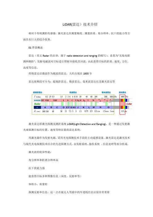
激光雷达分类:
关键技术
激光雷达融合激光、大气光学、雷达、光机电一体化和信号处理等诸多领域技术,下面逐一介绍各关键技术
1.激光器技术
激光器是激光雷达的核心
激光器种类很多,性能各异,需要综合考虑各种因素后加以选择
难题:相同表面特性的物体假设为漫反射其反光功率也随着距离的平方而线性衰减,如何保证同一类物体点云中呈现的Intensity保持一致?
Intensity校准技术
探测距离增加导致的误差具体来源于两个方面
返回至激光雷达的反射光功率随着距离的平方而线性衰减
返回至激光雷达的反射光经接收透镜成像在单点探测器的位置和距离有关
使用探测器阵列探测返回信号
优点
无扫描器件,成像速度快
集成度高,体积小
芯片级工艺,适合量产
缺点
激光功率受限,探测距离近
抗干扰能力差
角分辨率低
无法实现360°成像
6.信号处理技术
接收信号噪声种类
目标信号:由于目标反射在像平面上行成的信号(weak single)。
大气后向散射信号:激光冒充在照射一定厚度传播介质时所有其的向后散射干扰信号。
SLAMTEC思岚科技RPLIDAR 360度激光扫描测距雷达通讯接口协议与应用手册
等待应答数据
下一个请求…
图表 2-1 RPLIDAR 单次请求-应答通讯模式
外部系统应避免在该通讯模式中,RPLIDAR 还未对前一次请求做出应答前再次 发送请求。否则第二次的请求数据可能将被 RPLIDAR 丢弃。
1. RPLIDAR 通讯接口简介
外部系统通过 TTL 电平的 UART 串口信号与 RPLIDAR 测距核心进行通讯。通 过本文档定义的通讯协议,外部系统可以实时获取 RPLIDAR 的扫描数据、设备 信息、设备健康状态。并且通过相关命令调整 RPLIDAR 的工作模式。
TX
RX
外部系统
GND
图表 1-1 RPLIDAR 与外部系统通讯示意图
按照不同的请求类型,RPLIDAR 具有三种不同的请求/应答模式:
1. 标准的单次请求-单次应答模式
该模式用于外部系统向 RPLIDAR 获取相关信息的通讯中。RPLIDAR 在收到这 类请求后,将在必要的操作后通过单个应答包发送外部系统需要的数据。
RPLIDAR
外部系统
执行操作
发送请求报文 发送应答报文
SDK 与示例程序 ............................................................................................................................................... 3 2. 基本通讯协议 ......................................................................................................................................... 4
RPLIDAR S1 低成本360度激光雷达发展套件用户指南说明书

RPLIDAR S1 Low Cost 360 Degree Laser Range ScannerDevelopment Kit User Manual Model:S12019-06-18 rev.1.1CONTENTS (1)OVERVIEW (3)I TEMS IN THE D EVELOPMENT K IT (3)RPLIDAR S1 ...................................................................................................................... 错误!未定义书签。
USB A DAPTER. (4)CONNECTION AND USAGE (6)C ONNECTION (6)I NSTALL D RIVER FOR THE USB A DAPTER (6)R UN D EMO A PPLICATION (8)T ROUBLESHOOTING (10)M OTOR S PEED A DJUSTMENT (10)SDK INTRODUCTION AND USAGE (12)RPLIDAR S1P IN D EFINITION AND S PECIFICATION (12)P IN D EFINITION FOR THE USB A DAPTER (13)C ONFIGURE RPLIDAR S1S CAN F REQUENCY (15)SDK U SAGE (15)OPERATION RECOMMENDATION (16)P RE-H EATING FOR B EST P ERFORMANCE (16)A MBIENT T EMPERATURE (16)A MBIENT L IGHT (16)REVISION HISTORY (17)APPENDIX (18)I MAGE AND T ABLE I NDEX (18)OverviewRPLIDAR S1 development kit includes the matched tools used for evaluating RPLIDAR’s performance and initial development. After connecting the RPLIDAR S1 with PC via USB cable and connecting the power adapter to the USB cable, users can observe the cloud map of the environment scanning point collected by the RPLIDAR in RoboStudio and start development based on the SDK.Items in the Development KitRPLIDAR Development Kit contains:o RPLIDAR(PWM motor driver embedded)o USB Adaptero Micro-USB cableo Power cableRPLIDAR S1Power cableUSB adapterMicro-USBcableFigure 1-1 Items in the RPLIDAR Development KitRPLIDAR S1Figure 1-2 The RPLIDARThe RPLIDAR S1 development kit contains standard RPLIDAR S1 unit (S1M1). The RPLIDAR is embedded with logic IO drivable motor controller which can be used to configure the scan frequency by tuning motor speed. Developers can also choose to turn off the motor for power saving purpose.RPLIDAR usage and interface definition will be introduced in the coming sections. USB AdapterThe USB adapter comes with a dial switch. It can be used to switch the Baud rate from 115200 to 256000 or vice versa, which is compatible with RPLIDAR S1 and former RPLIDAR series. Please note that the Baud rate should be set as 256000 if the USB adapter is connected with RPLIDAR S1..Figure 1-3 RPLIDAR AdapterConnection and UsageConnectionRPLIDAR S1 can be easily connected to PC according to the following steps.1)Connect RPLIDAR S1 with the USB adapter.Figure 2-1 Connect RPLIDAR S1 and USB Adapter2)Connect the USB adapter to your PC via the Micro-USB cable. If the PC ison, after connecting the USB cable to your PC and connecting the poweradapter to the USB cable, the indicator light of the USB will light up but theRPLIDAR will not start scanning.Figure 2-2 Connect the USB Adapter to PC via Micro-USB Cable Install Driver for the USB AdapterThe USB adapter converts UART to USB by using CP2102 chip. You need to install the device driver for the chip. The driver can be found in the provided SDK package or downloaded from Silicon Labs’ official website:/products/mcu/Pages/USBtoUARTBridgeVCPDrivers.aspxHere’s the installation steps in Windows: after connecting the RPLIDAR with PC, please find the driver file “CP210x VCP Windows” and choose correct operating system version accordingly: x86 for 32-bit OS and x64 for 64-bit OS.Figure 2-3 Choose USB Adapter Driver for InstallationFigure 2-4 Start Page of USB Adapter Driver InstallationAfter Installing the driver according to the above installation steps, you will see corresponding serial port name in the [Control Panel] -> [Device and Printers]. Please refer to the below figure.Figure 2-5 Recognized Serial Port Name Matched with the USB AdapterRun Demo ApplicationSLAMTEC provides a Lidars plugin in RoboStudio for users in test and evaluation. You can view the scan result directly in the UI and save the scan result to files for further processing.This GUI demo can only run under Windows. For Linux and MacOS users, please refer to the other simple demo provided in the SDK.Please make sure you have connected RPLIDAR to PC by using USB adapter and installed the device driver correctly before running the demo application in RoboStudio. Launch RoboStudio and log in.Figure 2-6 RoboStudio Login PageIf the connection is ok, you shall see the user interface is shown as below.1. Click File->Lidars to open the lidar control panel in the left;2. Click Serial Ports to extend the lidar lists and you’ll find the RPLIDAR S1 previously connected to your PC;3. Click the RPLIDAR S1 icon to extend the tool buttons below the icon: the left one is to adjust the motor speed while the right one is to open the tool bar in the major work area as shown in Figure 2-7.Figure 2-7 The Lidar Plugin in RoboStudioThe serial number, version and model of the RPLIDAR S1 will show next with its icon in the lidar control panel. The supported commands of RPLIDAR are showed in the tool bar. The descriptions are listed in the bellow table.ButtonFigure 2-8 The Supported Commands of RPLIDAR in RoboStudioPress the Start Scan button,the scan data will be displayed as below(by default, the motor rotating speed should be about 10Hz.):Figure 2-9 The Scan Outline by RPLIDAR in RoboStudioRight click in the major working area to choose a range so as to zoom in or out the view.The scan frequency is also showed in the above interface. TroubleshootingWhen the scan core or the laser power works abnormally, the scan core will enter protection mode. This state can be retrieved via SDK API. If such scenariohappened, please send restart command to reset the scan core.Motor Speed AdjustmentDuring the running process, different motor rotating speed can be achieved bypressing the button, which can fit in different working environments or meet specific requirements. There will be a speed adjustment dialog box and dash board popped up for users to enter required speed. After entering a value, the motor will work as the settled rotating speed automatically. User can also drag the sliding handle to the required rotating speed.The current actual rotating speed will show in the upper left corner of the major work area. For instance, the actual rotating speed in the following screenshot is 12.88Hz.Figure 2-10 The Motor Speed Adjustment Dialogue of RPLIDAR in RoboStudioRPLIDAR S1 Interface Definition and SpecificationThe standard RPLIDAR S1 uses SH1.0-6P female receptacle and interface lead as communication interface. Detailed interface definition is shown in the following figure:Figure 3-1 RPLIDAR S1 InterfaceFigure 3-2 RPLIDAR Pin Definition and SpecificationSDK Introduction and UsageColor Signal NameTypeDescriptionMinTypicalMaxBrownVCCPowerTotal Power4.8V5V5.5VPurple OrangeGNDPowerGND0V0V0VYellow Green RX Input Serial port input of thescanner core0V3.3V 3.5V BlueTXOutputSerial port output ofthe scanner core0V3.3V3.5VRPLIDAR S1 uses the one 5V DC power supply for powering the scan motor and the scan core at the same time. No extra power is required.With build-in and speed-adjustable motor driver, RPLIDAR S1 can control the start, the stop and the rotating speed of the motor via the MOTOCTL signal.o Reference Design for RPLIDAR developmentFigure 3-3 RPLIDAR S1 Pins Reference DesignPin Definition for the USB AdapterThe USB adapter is also using XH2.54-5P specification socket, and it can be connected with RPLIDAR S1 directly. The pin definition is the same as the RPLIDAR S1.Power adapter specificationInputItem Unit Min Typical Max CommentsInput voltage VAC 90 100-240 264 Single phaseInput frequency Hz 47 50-60 63Input current A - - 0.4 When the input is 100Vac and in maximum loadInrush current (cold boot)A - - 30When the input is 230Vac and inmaximum loadV5.0GNDTXRXMOTOCTLPower(5V DC)UARTPWM GeneratorMCU/DSPRPLIDARFigure 3-4 RPLIDAR Power Adapter Input SpecificationOutputFigure 3-5 RPLIDAR Power Adapter Output SpecificationRipple wave and noise: When testing the ripple and noise, choose20Mhz wideband when setting the oscilloscope, and the output end should have a 0.1uF ceramic capacitor and a 10uF electrolytic capacitor connected in parallel. (the input should be in 100Vac-240Vac).Line/load regulationFigure 3-6 RPLIDAR Power Adapter Line/Load RegulationTurn-on delay3s when the input is 100Vac and at maximum load.2s when the input is 240Vac and at maximum load.Holdup timeAt least 30ms when shut the input is between 240Vac/50Hz and at maximum load.Rise time40ms when the input is between 100Vac-240 Vac and at maximum load.Output overshoot/undershoot7% is a maximum when powering on or off.Output load transient responseWhen the voltage output is between 4.75V and 5.25V, the load will change from 25% at maximum to 50% then back to 25%, or from 50% at maximum to 75% then back to 50%. The slope is 0.5A/us. The frequency is 100Hz. Output overshoot is lower than ±5%.Protection requirementShort circuit protection: when outputting short circuit, the input power will lower and will not have any affect. After ending the short circuit, the system will recover automatically.Overcurrent protectionOCSET: within 110%-180% of maximum load (with rated voltage), when outputting overcurrent, the output will go to hiccup mode. After ending the overcurrent, the system will recover automatically.Configure RPLIDAR S1 Scan FrequencyThe RPLIDAR S1’s scan frequency can be modified by invoking the related functions in the SDK to configure the motor speed.Please refer to the RPLIDAR protocol and application note for more information and the SDK for the sample code on RPLIDAR scan frequency.SDK UsageSLAMTEC provides RPLIDAR SDK support on both Windows and Linux platform. And users can embed the SDK source code to other operational system or embedded system quickly. Please refer to the SDK document for more information.Pre-Heating for Best PerformanceThe scan core will be heating when start working. We recommend pre-heating RPLIDAR (Start the scan mode and the scan motor is rotating) for more than 2 minutes to get the best measurement accuracy.Ambient TemperatureRPLIDAR’s measurement resolution is sen sitive to the ambient temperature. Improper use may even damage the sensor. Please avoid using RPLIDAR in extreme high temperature (>40 degree) and too low temperature (<-10 degree).Ambient LightCompared with RPLIDAR A series, RPLIDAR S1 performs better to resist ambient light interference, which supports it to work properly in outdoor environment.Image and Table IndexF IGURE 1-1I TEMS IN THE RPLIDAR D EVELOPMENT K IT (3)F IGURE 1-2T HE RPLIDAR (4)F IGURE 1-3RPLIDAR A DAPTER (5)F IGURE 2-1C ONNECT RPLIDAR S1 AND USB A DAPTER (6)F IGURE 2-2C ONNECT THE USB A DAPTER TO PC VIA M ICRO-USB C ABLE (6)F IGURE 2-3C HOOSE USB A DAPTER D RIVER FOR I NSTALLATION (7)F IGURE 2-4S TART P AGE OF USB A DAPTER D RIVER I NSTALLATION (7)F IGURE 2-5R ECOGNIZED S ERIAL P ORT N AME M ATCHED WITH THE USB A DAPTER (7)F IGURE 2-6R OBO S TUDIO L OGIN P AGE (8)F IGURE 2-7T HE L IDAR P LUGIN IN R OBO S TUDIO (9)F IGURE 2-8T HE S UPPORTED C OMMANDS OF RPLIDAR IN R OBO S TUDIO (9)F IGURE 2-9T HE S CAN O UTLINE BY RPLIDAR IN R OBO S TUDIO (10)F IGURE 2-10T HE M OTOR S PEED A DJUSTMENT D IALOGUE OF RPLIDAR IN R OBO S TUDIO (11)F IGURE 3-1RPLIDAR S1I NTERFACE (12)F IGURE 3-2RPLIDAR P IN D EFINITION AND S PECIFICATION (12)F IGURE 3-3RPLIDAR S1P INS R EFERENCE D ESIGN (13)F IGURE 3-4RPLIDAR P OWER A DAPTER I NPUT S PECIFICATION (14)F IGURE 3-5RPLIDAR P OWER A DAPTER O UTPUT S PECIFICATION (14)F IGURE 3-6RPLIDAR P OWER A DAPTER L INE/L OAD R EGULATION (14)。
RPLIDAR低成本360度二维激光扫描测距系统-Slamtec

*注:三角测距系统距离分辨率将随着实际距离值变化,RPLIDAR 的理论具体变化情况如下 图所示:
Millimeter (mm)
14
0.25%
12 0.20%
应用场合举例
本系统适用于如下领域: 家用看护/清洁机器人的导航与定位 通用的机器人导航与定位 智能玩具的定位于障碍物检测 环境扫描与 3D 重建 通用的同步定位与建图(SLAM)
4 / 11
Copyright 2009-2013 RoboPeak
Model: A1M1 Rev. 7
RPLIDAR 自身带有转速检测与自适应系统,雷达的扫描频率会自动随着实际 的电机转速做出调整。无需使用者为 RPLIDAR 提供复杂的供电系统,降低了总 体成本。并且外部系统可以通过通讯接口获取当前雷达的实际转速。
具体的供电与通讯接口的信息请参考后文的规格信息。
调制的激光可以有效避免在测距扫描过程当中的环境光与日光干扰。可以在 室内环境以及无阳光直射的室外环境下使用。
3 / 11
Copyright 2009-2013 RoboPeak
低成本 360 度二维激光扫描测距系统 简介与规格书
Model: A1M1 Rev. 7
输出数据
在 RPLIDAR 工作时,每次采样的数据将通过通讯接口输出。每个采样点的 数据将包括如下的信息。如果需要具体的数据格式和通讯接口的协议,请与 RoboPeak 联系。
数据类型 距离值 夹角 信号强度 起始信号
单位 毫米 度 级 (布尔值)
描述
RPLIDAR 距离当前采样点之间的实际距离 当前采样点相对于 RPLIDAR 自身朝向的夹角 当前采样点的信号强度 表示当前采集点是否属于一次新的扫描
- 1、下载文档前请自行甄别文档内容的完整性,平台不提供额外的编辑、内容补充、找答案等附加服务。
- 2、"仅部分预览"的文档,不可在线预览部分如存在完整性等问题,可反馈申请退款(可完整预览的文档不适用该条件!)。
- 3、如文档侵犯您的权益,请联系客服反馈,我们会尽快为您处理(人工客服工作时间:9:00-18:30)。
通讯与供电接口
供电与机械部分
图表 1-1 RPLIDAR A2 系统构成示意图
RPLIDAR A2 自身带有转速检测与自适应系统,扫描时角分辨率会自动随着实 际旋转频率做出调整。RPLIDAR 不需要使用者为其提供复杂的供电系统,这样 便降低了总体成本。如果需要了解当前雷达的实际转速,外部系统可以通过通 讯接口来获取相关数据。 具体的供电与通讯接口的信息请参考后文的规格信息。
4 / 19
Copyright (c) 2009-2013 RoboPeak Team Copyright (c) 2013-2016 Shanghai Slamtec Co., Ltd.
将从通讯接口中输出。
������
图表 1-2 RPLIDAR A2 工作原理示意图
在电机机构的驱动下,RPLIDAR 的测距核心将顺时针旋转,从而实现对周围环 境的 360 度全方位扫描测距检测。
2016-10-28 rev.1.0
RPLIDAR A2
低成本 360 度激光扫描测距雷达 简介与规格书
型号: A2M5 A2M6
OPTMAG
4K
上海思岚科技有限公司
目录
目录 ................................................................................................................................................................. 1 简介 ................................................................................................................................................................. 3
3 / 19
Copyright (c) 2009-2013 RoboPeak Team Copyright (c) 2013-2016 Shanghai Slamtec Co., Ltd.
系统构成及连接
RPLIDAR A2 主要包括激光测距核心以及使激光测距核心高速旋转的供电与机 械部分。正常工作时,测距核心将开始顺时针旋转扫描。用户可以通过 RPLIDAR 的通讯接口获取 RPLIDAR 的扫描测距数据,并通过 PWM 对旋转电 机的启动、停止以及旋转速度进行控制。
Class I
安全性与适用范围
RPLIDAR 系统采用低功率的红外线激光器作为发射光源,并采用调制脉冲方式 驱动,激光器仅在极短的时间内进行发射动作。因而可以确保对人类及宠物的 安全性,可以达到 Class I 级别的激光器安全标准。
*注:雷达扫描图与此处的环境示意图不 存在直接联系且不成比例关系。此处仅为 举例示意用途。
图表 1-3 RPLIDAR 扫描所得环境示意图 5 / 19
Copyright (c) 2009-2013 RoboPeak Team Copyright (c) 2013-2016 Shanghai Slamtec Co., Ltd. Nhomakorabea简介
RPLIDAR A2 由 SLAMTEC 公司开发的新一代低成本二维激光雷达(LIDAR),它 具有每秒高达 4000 次的高速激光测距采样能力。并配备了 SLAMTEC 独有的光 磁融合(OPTMAG)专利技术,克服了传统激光雷达的寿命限制,可长时间可靠 的稳定运行。 RPLIDAR A2M5/A2M6 为增强版二维激光测距雷达,可以实现在二维平面的 16 米半径范围内进行 360 度全方位的激光测距扫描,并产生所在空间的平面点 云地图信息。这些云地图信息可用于地图测绘、机器人定位导航、物体/环境建 模等实际应用中。 RPLIDAR A2 的典型旋转频率为 10hz (600rpm),在典型旋转频率下可以实现 0.9°的角度分辨率。并可随用户需求,在 5-15hz 范围内任意调整转转频率。 得益于 SLAMTEC 的高性能激光三角测距系统,RPLIDR A2 在各种室内环境以 及无日光直接照射的室外环境下均表现出色。同时,每一台 RPLIDAR A2 均在 出厂前经过了严格检测,确保所发射激光功率符合 FDA Class I 人眼安全等级。
工作原理和使用
RPLIDAR 采用了激光三角测距技术,再配合 SLAMTEC 研发的高速视觉采集处 理机构,它可进行每秒高达 4000 次的测距动作。每次测距过程中,RPLIDAR 将发射经过调制的红外激光信号,该激光信号在照射到目标物体后产生的反光 将被 RPLIDAR 的视觉采集系统接收,然后经过嵌入在 RPLIDAR 内部的 DSP 处 理器实时解算,被照射到的目标物体与 RPLIDAR 的距离值以及当前的夹角信息
系统构成及连接 ................................................................................................................................................ 4 工作原理和使用 ................................................................................................................................................ 4 安全性与适用范围 ............................................................................................................................................ 6 输出数据............................................................................................................................................................ 6 高速采样协议与协议兼容性 ............................................................................................................................ 7 应用场合............................................................................................................................................................ 7 规格信息 ......................................................................................................................................................... 8 测量性能............................................................................................................................................................ 8 激光功率信息.................................................................................................................................................... 9 光学窗口............................................................................................................................................................ 9 扫描数据坐标系定义 ...................................................................................................................................... 10 通讯与接口...................................................................................................................................................... 10 其他参数.......................................................................................................................................................... 14 自我保护和状态检测 .................................................................................................................................... 15 开发工具与支持............................................................................................................................................ 16 机械尺寸 ....................................................................................................................................................... 17 修订历史 ....................................................................................................................................................... 18 附录............................................................................................................................................................... 19 图表索引.......................................................................................................................................................... 19