15位置数旋转开关,ALPS开关SDKZ1F0200选型手册
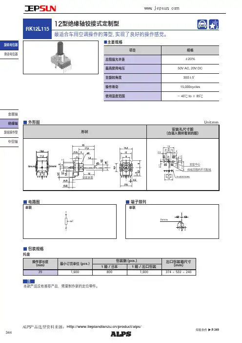
ALPS车用空调旋转电位器RK12L115选型手册
滑动电位器旋钮操作型金属轴中空轴本款产品没有推荐产品,需要制作新的定位零件。
注托盘包装规格焊接条件▲P.349/product/alps/ALPS产品选型资料来源:344旋转电位器旋钮操作型329金属轴绝缘轴旋转电位器滑动电位器型9mm size 11mm size 12mm size 14mm size 型号RK09K11RK09D11RK09K12RK09Y11LRK11KRK12L12RK12L115RK14K 单联2联单联2联单联2联照片端子安装方向Vertical / HorizontalHorizontal Vertical / Horizontal Vertical Vertical /Horizontal 轴套无有/无无有有/无使用温度范围-10℃ to + 70℃-40℃ to + 85℃-10℃ to + 70℃操作寿命5,000cycles10,000cycles1,000,000 cycles 15,000cycles 车用产品-----●-生命周期电性能总阻值(kΩ)5, 10, 20, 50, 100, 200105, 10, 20, 50, 100, 2005, 10, 20, 50, 1005, 10, 20, 50, 100, 200电阻规律15A, 1B, 3B, 15C 1B15A, 1B, 3B, 15C15A, 1B, 3B15A, 1B, 3B, 15C总阻值允许差±20%±30%±20%额定功率0.05W 0.03W 0.01W 0.05W最高使用电压50V AC 20V DC50V AC for AC only 50V AC 5V DC50V AC 20V DC50V AC for AC only 50V AC 20V DC50V AC for AC only 相互偏差--40dB to0dB 3dB max.--音量在ー40dB to 0dB 3dB max.音质用 在中心 2dB max.-音量在ー40dB to 0dB 3dB max.音质用 在中心 2dB max.绝缘电阻100MΩ min.250V DC 100MΩ min.500V DC 100MΩ min.250V DC 耐电压250V AC for 1minute500V AC for 1minute 300V AC for 1minute 中间输出端子无有/无无无 / 有(音质用)機械的性能定位无, 中央无无, 中央特别定做无, 中央终端止挡强度0.3N ・m -With out bushi n g 0.5N ・mWith bushing 0.6N ・m0.5N ・m 0.6N ・m轴推拉强度50N max.30N max.80N max.耐振性能10 to 55 to10Hz / 分、全振幅1.5mm, X, Y, Z 3方向各2小时轴形状平轴, 齿轴, 螺丝刀型平轴端子形状插入式页330336337341344345● 绝缘轴电位器焊接条件 ・・・・・・・・・・・・・・・・・・・・・・・・・・・・・・・・・・・・・・・・349● 电位器 使用时的注意事项 ・・・・・・・・・・・・・・・・・・・・・・・・・・・・・・・・・・・・・・・404● 电位器 测量方法·试验方法 ・・・・・・・・・・・・・・・・・・・・・・・・・・・・・・・・・・・・・・406● 电位器 电阻规律 ・・・・・・・・・・・・・・・・・・・・・・・・・・・・・・・・・・・・・・・・・・・408注表中的●符号表示适用于系列内的全部产品。
施耐德限位开关选型样本

i
目录
Osiswitch® 经典型
● 金属,XCKM 型 . . . . . . . . . . . . . . . . . . . . . . . . . . . . . . . . . . . . . . . . . . . . . . . . . . . . . . . . . . . . . . . . . . . . . . .72 ○完整开关带 3 个 ISO M20x1.5 电缆进线孔 . . . . . . . . . . . . . . . . . . . . . . . . . . . . . . . . . . . . . . . . . . 74 ● 金属,XCKM 型 . . . . . . . . . . . . . . . . . . . . . . . . . . . . . . . . . . . . . . . . . . . . . . . . . . . . . . . . . . . . . . . . . . . . . . .72 ○组件 . . . . . . . . . . . . . . . . . . . . . . . . . . . . . . . . . . . . . . . . . . . . . . . . . . . . . . . . . . . . . . . . . . . . . . . . . . . . . . . . . . . 76 ○组件:带触点的本体 . . . . . . . . . . . . . . . . . . . . . . . . . . . . . . . . . . . . . . . . . . . . . . . . . . . . . . . . . . . . . . . . . 78 ● 金属,XCKJ 型 . . . . . . . . . . . . . . . . . . . . . . . . . . . . . . . . . . . . . . . . . . . . . . . . . . . . . . . . . . . . . . . . . . . . . . . 84 ○完整开关 - 固定本体,带一个 ISO M20 x 1.5 电缆进线孔 . . . . . . . . . . . . . . . . . . . . . . . . . . . . . . . . . . . . . . . 86 - 固定本体,集成一个 M12 接头 . . . . . . . . . . . . . . . . . . . . . . . . . . . . . . . . . . . . . . . . . . . . . . . . . . . . . . 90 - 固定本体,集成一个 7/8" 16UN 接头. . . . . . . . . . . . . . . . . . . . . . . . . . . . . . . . . . . . . . . . . . . . . . . . 92 - 插入式本体,带一个 ISO M20 x 1.5 电缆进线孔. . . . . . . . . . . . . . . . . . . . . . . . . . . . . . . . . . . . . 88 ○组件:标准本体,固定或插入式 . . . . . . . . . . . . . . . . . . . . . . . . . . . . . . . . . . . . . . . . . . . . . . . . . . . . 94 ○组件 - 本体和触点模块 . . . . . . . . . . . . . . . . . . . . . . . . . . . . . . . . . . . . . . . . . . . . . . . . . . . . . . . . . . . . . . . . . . . . . . 96 - 低温应用 (-40 °C) . . . . . . . . . . . . . . . . . . . . . . . . . . . . . . . . . . . . . . . . . . . . . . . . . . . . . . . . . . . . . . . . . . . 106 - 高温应用 (+120 °C) . . . . . . . . . . . . . . . . . . . . . . . . . . . . . . . . . . . . . . . . . . . . . . . . . . . . . . . . . . . . . . . . . . . 119 ● 塑料,双绝缘,XCKS 型. . . . . . . . . . . . . . . . . . . . . . . . . . . . . . . . . . . . . . . . . . . . . . . . . . . . . . . . . . . . . 112 ○完整开关带一个 ISO M20 x 1.5 电缆进线孔. . . . . . . . . . . . . . . . . . . . . . . . . . . . . . . . . . . . . . . . . .114 ○组件 . . . . . . . . . . . . . . . . . . . . . . . . . . . . . . . . . . . . . . . . . . . . . . . . . . . . . . . . . . . . . . . . . . . . . . . . . . . . . . . . . . . 116 ○组件:本体,触点模块 . . . . . . . . . . . . . . . . . . . . . . . . . . . . . . . . . . . . . . . . . . . . . . . . . . . . . . . . . . . . . . 118
施耐德电气选型手册
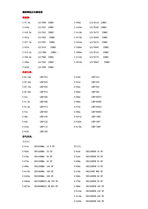
施耐德低压电器选型接触器:I<=7.5A LC1-D09 22M5C I<=10A LC1-D12 22M5C I<=15.3A LC1-D18 22M5C I<=21A LC1-D25 22M5CI<=27.2A LC1-D32 22M5CI<=34A LC1-D40 22M5C I<=42.2A LC1-D50 22M5C ;I<=55.5A LC1-D65 22M5CI<=68A LC1-D80 22M5CI<=82A LC1-D95 22M5C I<=98A LC1-D115 22M5CI<=128A LC1-D150 22M5C;I<=145A LC1-D170 22M5CI<=175A LC1-D205 22M5CI<=210A LC1-D245 22M5CI<=260A LC1-D300 22M5C I<=350A LC1-D410 22M5C I<=410A LC1-D475 22M5C I<=540A LC1-D620 22M5C热继电器:I<=0.16A LRD-01C I<=0.25A LRD-02C I<=0.40A LRD-03C I<=0.63A LRD-04C I<=1A LRD-05C I<=1.6A LRD-06C I<=2.5A LRD-07C I<=4A LRD-08C I<=6A LRD-10C I<=8A LRD-12C I<=10A LRD-14C I<=13A LRD-16C I<=18A LRD-21C I<=24A LRD-22C I<=32A LRD-32C I<=38A LRD-35C I<=50A LRD-3357C I<=65A LRD-3359C I<=70A LRD-3361C I<=80A LRD-3363C I<=104A LRD-4365 I<=120A LRD-4367 I<=140A LRD-4369空气开关:电机的:I<=11A NSX100HMA 12.5 3PI<=23A NSX100HMA 25 3PI<=45A NSX100HMA 50 3PI<=70A NSX100HMA 80 3PI<=90A NSX100HMA 100 3PI<=140A NSX160HMA 160 3PI<=230A NSX250HMA 250 3PI<=360A NSX400HMIC2.3M 400 3P I<=570A NSX630HMIC2.3M 630 3P 配电的:I<=13A NSX100HTM 16 3P I<=18A NSX100HTM 25 3P I<=29A NSX100HTM 32 3P I<=35A NSX100HTM 40 3P I<=45A NSX100HT M50 3P I<=55A NSX100HTM 63 3P I<=70A NSX100HTM 80 3P I<=90A NSX100HTM 100 3P I<=110A NSX160HTM 125 3P I<=140A NSX160HTM 160 3P I<=180A NSX250HTM 200 3PI<=225A NSX250HTM 250 3P I<=360A NSX400HMIC2.3 400 3PI<=600A NSX630HMIC2.3 630 3P三、中间继电器40、31、22CA2-DN□□M5C常闭接点数量常开接点数量四、框架断路器:I=800A 型号:MT08N13P MIC 5.0AI=1000A 型号:MT10N13P MIC 5.0AI=1250A 型号:MT12N13P MIC 5.0AI=1600A 型号:MT16H13P MIC 5.0AI=2000A 型号:MT20H13P MIC 5.0AI=2500A 型号:MT25H13P MIC 5.0AI=3200A 型号:MT32H13P MIC 5.0AI=4000A 型号:MT40H13P MIC 5.0ATD101B(分体式,P<=45kW)TD101BB(分体式,P>45kW,用三只电流互感器)TD101B-#-M(#用数字1~5代替,1:1A、2:6.3A、3:25A、4:63A、5:100A)(M代表有4~20mA输出,不输出时取消M)TD101BB-#-M(#用数字6~7代替,6:200A、7:400A)(M代表有4~20mA输出,不输出时取消M) 并注明电流互感器的变比。
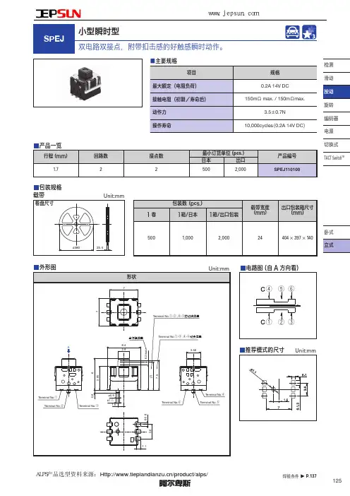
ALPS小型瞬时型按动开关SPEJ系列选型手册
产品一览
行程 (mm) 1.7
回路数 2
接点数 2
最小订货单位 (pcs.)
日本
出口
500
2,000
产品编号 SPEJ110100
检测 滑动 按动 旋转 编码器 电源 切换式 TACT SwitchTM
包装规格 载带
卷盘尺寸
Unit:mm
包装数 (pcs.)
载带宽度 出口包装箱尺寸
1卷
1箱/日本 1箱/出口包装
■浸焊方式的参考举例 适用于 For PC board 端子型
系列
SPPJ3 SPUN SPUJ, SPUP, SPPH2, SPPH4 SPPJ2, SPPH1, SPED2, SPED4, SPEF
预热温度 100℃ max.
项目 预热温度时间 60s max.
100℃ max.
60s max.
操作部 强度
工作 方向
拉引 方向
50N
30N
—
5N for 1minute 50N
50N
0.5N for 1minute
100MΩ 100MΩ min.
max.
100V DC
49N
50N
—
—
—
耐环 境性能
耐寒性能 耐热性能 耐湿性能
–40±2℃ for 96h
–20±2℃ for 96h 85±2℃ for 96h 40±2℃, 90 to 95%RH for 96h
———
———
焊接温度 260±5℃ 260±5℃ 260±5℃ 260±5℃
浸焊 焊接浸渍时间 5±1s 10±1s 5±1s 10±1s
ALPS产品选型资料来源:/product/alps/ 137
CKS 旋钮开关产品说明书
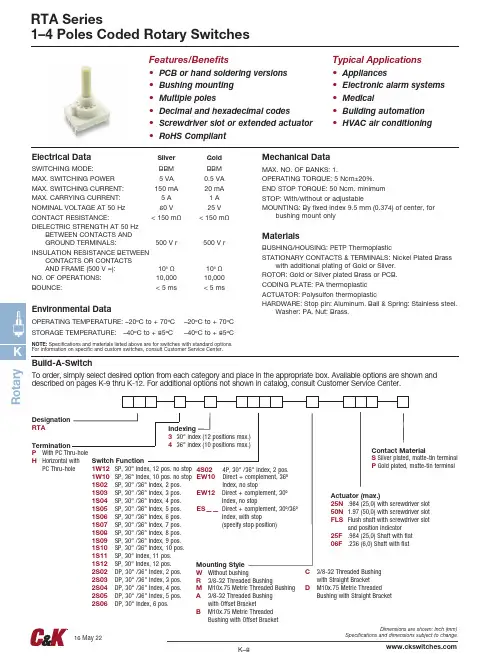
R o t a r yRTA Series1–4 Poles Coded Rotary SwitchesFeatures/Benefits • P CB or hand soldering versions • Bushing mounting • Multiple poles• Decimal and hexadecimal codes• Screwdriver slot or extended actuator • RoHS CompliantTypical Applications • A ppliances• Electronic alarm systems • Medical• Building automation • HVAC air conditioningElectrical DataSilver GoldSWITCHING MODE: BBM BBM MAX. SWITCHING POWER 5 VA 0.5 VA MAX. SWITCHING CURRENT: 150 mA 20 mA MAX. CARRYING CURRENT: 5 A 1 A NOMINAL VOLTAGE AT 50 Hz 60 V 25 V CONTACT RESISTANCE: < 150 mΩ < 150 mΩDIELECTRIC STRENGTH AT 50 HzBETWEEN CONTACTS AND GROUND TERMINALS: 500 V r 500 V r INSULATION RESISTANCE BETWEENCONTACTS OR CONTACTS AND FRAME (500 V =): 109 Ω 109 ΩNO. OF OPERATIONS: 10,000 10,000BOUNCE: < 5 ms < 5 msEnvironmental DataOPERATING TEMPERATURE: –20ºC to + 70ºC –20ºC to + 70ºC STORAGE TEMPERATURE: –40ºC to + 85ºC–40ºC to + 85ºCNOTE: Specifications and materials listed above are for switches with standard options. For information on specific and custom switches, consult Customer Service Center.Mechanical DataMAX. NO. OF BANKS: 1.OPERATING TORQUE: 5 Ncm±20%.END STOP TORQUE: 50 Ncm. minimum STOP: With/without or adjustableMOUNTING: By fixed index 9.5 mm (0.374) of center, forbushing mount onlyMaterialsBUSHING/HOUSING: PETP ThermoplasticSTATIONARY CONTACTS & TERMINALS: Nickel Plated Brasswith additional plating of Gold or Silver.ROTOR: Gold or Silver plated Brass or PCB.CODING PLATE: PA thermoplastic ACTUATOR: Polysulfon thermoplasticHARDWARE: Stop pin: Aluminum. Ball & Spring: Stainless steel.Washer: PA. Nut: Brass.Build-A-SwitchTo order, simply select desired option from each category and place in the appropriate box. Available options are shown and described on pages K-9 thru K-12. For additional options not shown in catalog, consult Customer Service Center.Designation RTAIndexing3 30° index (12 positions max.)4 36° index (10 positions max.)TerminationP With PC Thru-holeH Horizontal withPC Thru-holeSwitch Function 1W12 SP, 30° Index, 12 pos. no stop 1W10 SP, 36° Index, 10 pos. no stop 1S02 SP, 30° /36° Index, 2 pos.1S03 SP, 30° /36° Index, 3 pos.1S04 SP, 30° /36° Index, 4 pos.1S05 SP, 30° /36° Index, 5 pos.1S06 SP, 30° /36° Index, 6 pos.1S07 SP, 30° /36° Index, 7 pos.1S08 SP, 30° /36° Index, 8 pos.1S09 SP, 30° /36° Index, 9 pos.1S10 SP, 30° /36° Index, 10 pos.1S11 SP, 30° Index, 11 pos.1S12 SP, 30° Index, 12 pos.2S02 DP, 30° /36° Index, 2 pos.2S03 DP, 30° /36° Index, 3 pos.2S04 DP, 30° /36° Index, 4 pos.2S05 DP, 30° /36° Index, 5 pos.2S06 DP, 30° Index, 6 pos.Contact MaterialS Silver plated, matte-tin terminal P Gold plated, matte-tin terminalActuator (max.)25N .984 (25,0) with screwdriver slot 50N 1.97 (50,0) with screwdriver slot FLS F lush shaft with screwdriver slot and position indicator 25F .984 (25,0) Shaft with flat 06F .236 (6,0) Shaft with flatMounting StyleW Without bushingR 3/8-32 Threaded BushingM M10x.75 Metric Threaded Bushing A 3/8-32 Threaded Bushing with Offset BracketB M10x.75 Metric Threaded 4S02 4P, 30° /36° Index, 2 pos. EW10 Direct + complement, 36º Index, no stopEW12 Direct + complement, 30º Index, no stopES —— Direct + complement, 30º/36º Index, with stop (specify stop position)C3/8-32 Threaded Bushing with Straight BracketD M10x.75 Metric Threaded Bushing with Straight Bracket4 36 index, 10 positions max.Both commons must be connected by user to ground.3 30 index, 12 positions max.HHorizontal with PC Thru-holeNote: “H” termination only available with the following options: 1. With A or B mounting styles 2. 36º degree indexing 3. Up to 5 positions max.3027,67()(RotaryRTA Series1-4 Poles Coded Rotary Switches1 POLE2 POLES 4 POLES BCD + COMPLEMENTS1 POLE2 POLES 4 POLES BCD + COMPLEMENTS4P MODELS SCHEMATICPos. 1121 1222 1323 1424C1 C2 C3 C4DP MODELS SCHEMATICPos. 112131415161122232425262C1 C2SP MODELS SCHEMATICPos.NOTE: Layout view fromcomponent side.Indexing Option Code 3, 30 INDEXING ANGLE PCB LAYOUTIndexing Option Code 4, 36 INDEXING ANGLE PCB LAYOUTNO.POLESMODELNO.2W052W062S022S032S042S052S064S02SWITCHFUNCTION5 PositionsNo StopINDEXDP6 PositionsNo Stop2 Positions3 Positions4 Positions5 Positions6 Positions2 Positions30º/36º30º30º/36º30º/36º30º/36º30º/36º30º30º/36º4PEW10EW12ES——Direct + complement, No stopDirect + complement, No stopDirect + complement, with stop (specify stop position)NO.POLESMODELNO.1W121W101S021S031S051S061S081S091S101S111S12SWITCHFUNCTION12 PositionsNo StopINDEXSP10 PositionsNo Stop3 Positions5 Positions6 Positions9 Positions10 Positions11 Positions12 Positions30º36º30º/36º30º/36º30º/36º30º/36º30º/36º30º30º8 Positions30º/36º2 Positions30º/36ºINDEXMODELNO.SWITCH FUNCTION36º30º30º & 36ºRotaryThird Angle RTA Series1-4 Poles Coded Rotary Switches.87422,2().3388,59()R Mounting3/8 - 32 UNEF.374(9.5).385 DIA (9.8 Ø).134(3.4Ø)PANEL MOUNTING.87422,2().0711,8().60015,2().61815,7().1884,8().0310,8().3388,59()M10METRIC.732(18,6)P ANEL MOUNTING.134 DIA.(3,4ø).374(9,5).402 DIA.(10,2ø).495(12,6)MOUNTING STYLEM M10 x .75 MERTIC THREADED BUSHINGW WITHOUT BUSHINGB M10 x .75 METRIC THREADED BUSHING WITH BRACKETD M10 x .75 METRIC THREADED BUSHING WITH STRAIGHT BRACKETC 3/8-32 THREADED BUSHING WITH STRAIGHT BRACKETR 3/8-32 THREADED BUSHINGNote: A mounting style only available with H termination.Note: B mounting style only available with H termination.Note: W mounting style not available with H termination.Note: R mounting style not available with H termination.Note: M mounting style not available with H termination..618(15,7).600(15,24).071(1,8).031(0,8).188(4,77).735(18,67)PANEL MOUNTING.385 DIA (9.8 Ø)PANEL MOUNTING.60015,24().0711,8().61815,7().87422,2().0310,8().3188,07().60015,24().0711,8().0310,8().73518,67().3188,07().61815,7().385 DIA (9.8 Ø)PANEL MOUNTING.6015,2().328,1()2X ø.082()6X .102,5().307,6()7X ø.040,9()AB C D E F G .6015,2().328,1()2X ø.082()6X .102,5().307,6()7X ø.040,9()AB C D E F G PANEL MOUNTING.6015,2().194,8().307,6()6X .102,5()2X ø.082,1()7X ø.040,9()AB C D E F G .6015,2().194,8().307,6()6X .102,5()2X ø.082,1()7X ø.040,9()AB C D E F G 1.0025,4().6015,2()6X .102,5()14X ø.040,9()AB C D E F G HI J K L M N 1.0025,4().6015,2()6X .102,5()14X ø.040,9()AB C D E F G HI J K L M N 1.0025,4().6015,2()6X .102,5()14X ø.040,9()AB C D E F G HI J K L M N A 3/8-32 THREADED BUSHING WITH BRACKETK RotaryPART NO.Y200300200PCH Standard MetricNOTE: Additional nuts and lockwashers available separately, see section “Technical Data and Additional Hardware”.。
施耐德限位开关选型样本
● 小型设计,塑料, XCMN 型 . . . . . . . . . . . . . . . . . . . . . . . . . . . . . . . . . . . . . . . . . . . . . . . . . . . . . . . . 24 ○完整开关,成型电缆 . . . . . . . . . . . . . . . . . . . . . . . . . . . . . . . . . . . . . . . . . . . . . . . . . . . . . . . . . . . . . . . . . 26 ● 小型设计,塑料, XCJ 型 . . . . . . . . . . . . . . . . . . . . . . . . . . . . . . . . . . . . . . . . . . . . . . . . . . . . . . . . . . . 50 ○完整开关,带电缆密封套 . . . . . . . . . . . . . . . . . . . . . . . . . . . . . . . . . . . . . . . . . . . . . . . . . . . . . . . . . . . . .52 ● 紧凑设计,塑料, XCKN 型 . . . . . . . . . . . . . . . . . . . . . . . . . . . . . . . . . . . . . . . . . . . . . . . . . . . . . . . . . 54 ○完整开关,带 1 个 ISO M20 x 1.5 电缆进线孔 . . . . . . . . . . . . . . . . . . . . . . . . . . . . . . . . . . . . . . . 56 ● 紧凑设计,金属, XCE 型. . . . . . . . . . . . . . . . . . . . . . . . . . . . . . . . . . . . . . . . . . . . . . . . . . . . . . . . . . . 58 ○完整开关,带电缆密封套 . . . . . . . . . . . . . . . . . . . . . . . . . . . . . . . . . . . . . . . . . . . . . . . . . . . . . . . . . . . . 60
elesa-clayton 旋转开关手柄手轮 使用手册说明书
R o t a r y c o n t r o l sELESA-CLAYTON rotary controls are used to set and regulating a wide variety of machine functions.The device consists of:- a handwheel/knob, to manoeuvre the control spindle, thus changing the position of the machine element- a position indicator, which provides the position of the machine element.ELESA-CLAYTON position indicators can be classified according to the type of reading or movement:2.1 Types of reading ANALOGUE: the reading is displayed by means of two rotating pointers over a graduated dial.DIGITAL-ANALOGUE: the reading is directly displayed by means of a roller counter and a rotating pointer over a graduated dial.DIGITAL: the reading is directly displayed by means of a roller counter.LCD DIGITAL: the reading is directly displayed by means of a digital electronic display.The analogue indicators are normally provided with a graduated dial and two pointers which indicate the number of turns and part of a turn made by the control spindle starting from an initial position zero. In general these indicators are used to regulate flows, capacities, strokes, setting of speed variators, etc.The indicators with digital-analogue, digital and LCD digital reading are provided with a roller counter or a display which indicates the linear displacement of the machine element connected to the control spindle from the initial position zero.2.2 Types of movementGRAVITY (page 464): is used when the handwheel spindle is horizontal or max 60° inclined. The rotation of the handwheel with the indicator makes the pointers move while the dial, appropriately counterbalanced, is kept still by the gravitaty force.POSITIVE DRIVE (page 470): is used on spindles in any position. The rotation of the handwheel with the indicator makes the pointers move while the dial is kept still by an anchor pin fitted to the machine.DIRECT DRIVE (page 488): is used on control spindles in any position, the indicator is directly mounted on the control spindle and is kept in position by means of a referring back pin.2.3 The indicators are normally supplied separately from their relative handwheels/knobs, exceptintegral models, whose indicator is fitted in during the production.ROTARY CONTROLS1. GENERAL FEATURES2. POSITIONINDICATORSR o t a r y c o n t r o l s3. HOW TO SELECT THE ROTARY CONTROL4. SPECIALEXECUTIONS3.1 Choice of the type of reading (see 2.1). Establish if is necessary to display a number of turnsor a linear displacement. For the first application choose an analogue indicator. For the second one choose a digital-analogue, digital or LCD digital indicator.3.2 Establish the indicator and the spindle position on which depends the choice of the requestedmovement: gravity, positive drive or direct drive (see 2.2).3.3 Establish the required ratio for analogue types or the reading after one revolution for thefollowing types: digital-analogue, digital and LCD digital.3.4 Establish the direction of rotation. For clockwise increasing readings (right) = D. For anticlockwiseincreasing readings (left) = S.3.5 Consider the conditions of use of the handwheel i.e. outdoors, vibrations, corrosive environments,etc. See the complete data on the page of the chosen indicator.3.6 Choose the appropriate handwheel/knob for the application considering the diameter and the grip required to transmit the necessary torque. Other factors to take into consideration are the control spindle diameter and whether a handle is required for quick operations.4.1 The ELESA-CLAYTON position indicators standard range available on this catalogue satisfiesmost applications. Changes to adapt the indicator to particular applications are possible, for example: - special dials for indicators with analogue or digital-analogue reading, on customers indications- stainless steel metal parts for application on machines and equipment where laws or particular hygienic and environmental factors make it mandatory to use corrosion resistant materials- gravity indicators with analogue reading with glycerine-filling for high vibration applications, which may interfere with the reading, or to avoid condensation on the indicator window- special ratio on request and for sufficient quantities, developed by ELESA TechnicalDepartment.R o t a r y c o n t r o l s1.1 Suitable for use on control spindles with horizontal or max 60° inclined position.1.2 The movement is housed in a sealed case (fig. 1). It consists of a counterweight system, fittedon a precision ballrace, which rotates on a central spindle integral with the indicator case, fitted on the handwheel/knob. At the end of the spindle there is a red pointer, which rotates with the handwheel/knob. A series of gears with different ratios transmits the rotation of the spindle to a black pointer. On the counterweight is also fixed a graduated dial. If the indicator is fitted on spindles with horizontal position (or max 60° inclined) the dial is kept still by the gravity force and the pointers rotate over it when the handwheel/knob turns.2. RATIOS3. CHOICE OF THE INDICATOR RATIOFig.2GRAVITY INDICATORS1. FEAUTURES2.1 Each complete turn of the big pointer (red) corresponds to a fraction of turn of the small pointer(black). The number of turns of the red pointer to make the black pointer to carry out one complete turn is the ratio of the indicator. Example: a ratio of 12:1 means that to 12 turns of the red pointer correspond to a complete turn of the black pointer (fig. 2).12 turns of the handwheel cover the entire setting range. For each turn of the handwheel, the black pointer indicates 1/12 of the entire dial.3.1 Set the control spindle to the initial or referring position.3.2 Count the number of turns of the control spindle to cover the entire setting range.3.3 The result of this operation is the ratio. Should it not correspond to a standard ratio, choosethe next highest one.Fig.1IZN.MBT.VHT.VRTP .475476477478•R o t a r y c o n t r o l s3.4 For an optimal dial reading, and therefore for a more precise reading we recommend tochoose a ratio which is as near as possible to the handwheel turns required to cover the entire setting range. For instance, if 11 turns are required, the ratio 12:1 is the most convenient, because 11/12 of the available graduation will be used. If 24:1 ratio would be chosen, only 11/24 of the graduation would be used and reading would be less accurate.3.5 Indicators with standard ratios are normally on stock to suit most requirements.4.1 Dials are available for all standard ratios in both clockwise (D) or anticlockwise (S)configurations.4.2 Standard dials give a number which can be translated by means of conversion tables to thevalue of the set-up executed.4.3 be supplied to have a direct reading.5.1 however used on spindles max 60° inclined, but the accuracy decreases as the angle inclination a ° increases (fig. 3).6.1 If the hole of the handwheel/knob hub or boss needs to be reamed for coupling to the controlspindle, please refer to the handwheel/knob relevant page for further details and advice.6.2 Assembly of the indicators to handwheels/knobs: - couple the handwheel to the control spindle by means of a pin or a grub screw - set the control spindle to the initial or referring position, by rotating the handwheel - turn the indicator, by keeping it in the hands, until the pointers are in zero position- fit the zeroed indicator into the handwheel/knob and uniformly tighten the radial securing screws with a moderate torque to prevent distortion of the indicator case and thus locking the movement.6.3 Assembly of integral indicators (built-in in the handwheel): - set the control spindle to the initial or referring position- turn the indicator, by keeping it in the hands, until the pointers are in zero position- couple the integral indicator to the control spindle by tightening the grub screw, after checking that spindle and indicator are in zero position.4. DIALS5. ACCURACY6. ASSEMBLY INSTRUCTIONSExample of gravity indicator descriptionFig.3VD+I VDC.VDSC+I VAD.479480482484Electronic spindle position indicator system• APPLICATIONThe system provides an efficient electronic check of manual drive shafts with considerably lower costs than with completely automatized systems.• EASY TO USEThe system can be used to set a number of spindles quickly (set-up profile) and in a completely guided way.• SET-UP TIME REDUCTIONThe field tests carried out on machines provided with DE51 electronic indicators, give a set-up time reduction by 30÷40% compared to those with the traditional mechanical position indicators.• ABSOLUTE OPTICAL ENCODERDE51 measuring system is based on an absolute optical multi-turn encoder and it is not affected by magnetic fields. Therefore it is able to guarantee perfect operation, even in the presence of electric motors. Thanks to the long-life lithium battery (more than 10 years of life-espectancy) spindle positioning variations can be registered even when the power supply is switched off and it prevents the loss of the preset values in case of an electrical power failure.• SAFETYThe connection of DE51 electronic indicators directly to the PLC of the machine, functions also as a safety system, preventing the machine fromstarting to work if the set-up profile is not completed.• RETROFITThe small dimensions of DE51 indicators allow the retrofit of the existingmachines, without any structural modifications.。
MERZ 旋转式开关 Cam Switches 说明书
旋转式开关Cam SwitchesMERZ旋转式产品系列MERZ CAM SERIES旋转式开关旋转式开关根据其触点配置,开关中带有1、2或3个(仅111系列)双遮断触点回路。
每个导电路径均由一对结实结构的端子和一个连动机件组成。
透过旋转即可打开,并经由弹簧关闭。
指示装置含有4个不同的切换角度及扭矩。
防误触电击的旋转开关配有带固定的螺钉。
所有端子均可由一般螺丝刀简便固定,漏斗形电缆入口以及类似腔体的设计。
电缆末端的挡块可确保正确的插入深度。
Cam SwitchesCam Switches according to their contact arrangement are fitted with switching chambers with 1, 2 or 3 (series 111 only) double interrupted conduct paths. Each conduct path is arranged of 2 firmly seated terminals and one mobile contact bridge which is guided by a plunger. The contact bridge is positively opened by the cam and closed by a spring. The indexing device is available in different torques and 4 different switching angles. The finger proof Cam Switches are equipped with screws with captive screw heads. All terminals are fitted with screwdriver guiding, funnel-shaped cable entries and in chamber like design. Cable end stops assure the correct insertion depth.规格总览OVERVIEW SPECIFICATIONS参数Specific ations從/from到/to额定工作电流 Ie AC-21ARated operational current Ie AC-21A A16125符合认证 IEC 60947-3, EN 60947-3 ACC. IEC 60947-3, EN 60947-3额定工作电压 UeRated operational voltage Ue额定不间断电流 Ith offenRated uninterrupted current Ithopen额定不间断电流 Ithe 封裝的Rated uninterrupted current Itheencapsulated额定绝缘电压 Ui 绝缘等级 C 符合 VDE 0110Rated insulation voltage UiInsulation group C acc. VDE 0110额定冲击耐受电压 Uimp (III/3)Rated impulse withstand voltage Uimp(III/3)段位自定义马达开关Motor switch for operational switching单相马达开关Single-phase motor马达开关Motor switch主开关Main switch维护开关Maintenance switchV690500A20125A20125V690500kV46kW322 230 V 3~kW5,545 400 V 3~kW5,545 690 V 3~kW2,211 230 V 3~kW318,5 400 V 3~kW437 230 V 3~kW7,545 400 V 3~kW7,545 690 V 3~断开和关合能力使用类别 AC-3MAKING BREAKING CAPACITY UTILISATION CATEGORY AC-3断开和关合能力使用类别 AC-23A/(B)MAKING BREAKING CAPACITY UTILISATION CATEGORY AC-23A/(B)前板安装Front mounting底部安装Base mounting外壳封闭式EnclosureDESIGN FRONT MOUNTING双孔/四孔安装- 1简易旋钮(P25/P25.9无挂锁)ON-OFF指示 面板 / MN 104-756型2/4-hole mounting with frontplate without padlock 型/Type: MN 104 - 756单孔安装- 3中央圆孔(Φ=22,5 / 30,5 mm) 简易旋鈕(P25/P25.9无挂锁)ON-OFF指示面板22,5 / 30,5 mm Central mounting with frontplate without padlock型/Type: MN 104,105,107,111,151,251单孔安装- 1中央圆孔(Φ=16,0 mm)简易旋钮(P25/ P25.9无挂锁)MN 105型16,0 Central mounting without frontplate without padlock 型/Type: MN 105双孔/四孔安装- 3美规带锁旋钮(灰/黑)MN 104,105,111,151,251,451型 2/4-hole mounting with lockout handle for 3 padlocks型/Type: MN 104,105,111,151,251,451单孔安装- 5中央圆孔(Φ=22,5 / 30,5 mm)美规带锁旋 钮(灰/黑)锁孔三方位可选22,5 / 30,5 mm Central mounting with lockout handle for 3 padlocks 型/Type: MN 104,105,111,151,251单孔安装- 2中央圆孔(Φ=22,5 / 30,5 mm)简旋钮(P25/ P25.9无挂锁)MN 104,105,107,111,151,251型22,5 / 30,5 Central mounting without padlock 型/Type: MN 104,105,107,111,151,251双孔/四孔安装- 2單锁孔旋鈕(EVS) / ON-OFF指示面板 MN 104,105,151型2/4-hole mounting with frontplate with lockout handle for 1 or 2 padlock 型/Type: MN 104,105,151单孔安装- 4中央圆孔(Φ=22,5 / 30,5 mm) 單锁孔旋鈕 (EVS) / ON-OFF指示面板22,5 / 30,5 mm Central mounting with front -plate with lockout handle for 1 or 2 padlock 型/Type: MN 104,105,151依设计需求提供 多色搭配Available coloursfor all housing designsDESIGN BASE MOUNTING配电盘/箱体- 1旋钮内置箱体(不外露) 、ON-OFF指示面板 螺丝 /卡扣式安装、MN 104,105型Distribution board mounting 1 with screwand snap-on mounting 型 /Type: MN 104,105底部安装- 1簡易旋鈕(P25/P25.9无挂锁)门板轴心对接 器件组、ON-OFF指示面板Cover coupling 1 with front plate without padlock型 /Typ: MN 104,105,111,151,251,451底部安装- 2简易带锁旋钮(EVS)单锁孔门板轴心对接 器件组MN 104,105,151型Door coupling 2 with lockout handle for 1 or 2 padlocks型/Typ: MN 104,105,151底部安装- 3美规带锁旋钮(灰/黑)、锁孔三方位可选门 板轴心对接器件组Cover coupling 3 with locklout handle for 3 padlocks型 /Typ: MN 104,105,111,151,251,451底部安装- 3美规带锁旋钮(红/黄)、锁孔三方位可选门 板轴心对接器件组MN 104 - 756型Door coupling 3 with locklout handle for 3 padlocks型/Typ: MN 104 - 756底部安装- 1簡易旋鈕(P25/P25.9无挂锁)门板轴心对接 器件组、ON-OFF指示面板Door coupling 1 with front plate without padlock 型/Typ: MN 104 - 756配电盘/箱体- 2旋钮内置箱体(不外露) 、ON-OFF指示面板螺丝 /按扣式安装、MN 104,105型Distribution board mounting 2 with screw and snap-on mounting 型 /Typ: MN 104,105底部安装- 2單锁孔旋鈕(EVS) / 门板轴心对接器件组 ON-OFF指示面板Cover coupling 2 with lockout handle for 1 or 2 padlocks型 /Typ: MN 104,105,151依设计需求提供 多色搭配Available coloursfor all housing designs外壳封闭式壁挂安装DESIGN WALL MOUNTING ENCLOSED壁挂式旋转式开关外壳封闭式设计 旋转式开关类型: 105,111,151,251,451Wall mounting enclosed design,with lockout handle for 3 padlocks 壁挂式旋转式开关外壳封闭式设计 旋转式开关类型: 105,111,151,251,451Wall mounting enclosed design,without padlock 壁挂式旋转式开关外壳封闭式设计旋转式开关类型: 105,111,151Wall mounting enclosed design,key operation壁挂式旋转式开关外壳封闭式设计旋转式开关类型: 105Wall mounting enclosed design,with lockout handle for 1 or 2 padlocks依设计需求提供 多色搭配Available coloursfor all housing designs外壳封闭式开关-壁挂安装DESIGN WALL MOUNTING ENCLOSED壁挂式旋转式开关外壳封闭式设计美规带锁旋钮(红/黄)、锁孔三方位可选型/Type: 105, 111, 151, 251, 451Wall mounting enclosedwith lockout handle for 3 padlocks壁挂式旋转式开关外壳封闭式设计旋转式开关类型- 铝型/Type: 105, 111, 151Wall mounting enclosed - Aluminiumwith lockout handle for 3 padlocks 壁挂式旋转式开关外壳封闭式设计旋转式开关类型 - 聚碳酸酯纤维型/Type: 451, 656, 756Wall mounting enclosed - Polycarbonate plastic with lockout handle for 3 padlocks壁挂式旋转式开关外壳封闭式设计壁挂式旋转式安全开关外壳封闭式设计型/Type: 105, 151, 251, 451Wall mounting enclosed / Safety-switchwith lockout handle for 3 padlocks 依设计需求提供 多色搭配Available coloursfor all housing designs接点图CONTACT DIAGRAMSOn-Off 开关分接开关135246Ein-Aus Schalter On-Off switchesA2L1Gruppenschalter Group switchesV41NAB双切/三切开关8101259UmschalterChange-over switchesZ1416132461多段开关多段集成开关2L1Gruppenschalter Group switchesV41NAB2L1Gruppenschalter Group switchesV41NAB接点图CONTACT DIAGRAMS电流切换开关电压切换开关1Amperemeter Umschalter Ammeter selector switches V1L123L 2A L2L3K KI L K KIL K KIL1Voltmeter SchalterVoltmeter selector switchesV1NL2L3N2V反向开关星型/三角切换开关WWendeschalter Reversing switchesL1L2L3U1V1W1SStern-Dreieck-Schalter Star-delta switchesL1L2L3U1V1W1U2W2V2接点图CONTACT DIAGRAMS变速开关单相启动器开关mit Anlaufkondensator with starting capacitor mit Anlaufkondensator with starting capacitor Betriebskondensator running capacitormit Anlaufkondensator with starting capacitormit Anlaufkondensator with starting capacitorPPolumschalter Multi-speed switchesL1L2L31U1V1W2U2W2V EEinphasen-Anlassschalter Single-phase starter switchesZ1U2U1L1NC C B A1669020202,247,57,51,0 - 41x106+50/-25316 - 1035,55,531,0 - 2,5+40/-25550,51,5369042510192-5000,816600M3MN 1042569025252,247,57,51,0 - 41x106+50/-25314 - 1035,55,531,0 - 2,5+40/-25550,51,53690425510240-6900,816600M3MN 1052069025202,257,5111,0 - 41x106+50/-25316 - 1045,57,531,0 - 2,5+40/-251111,5-6904256240-500110600M3,5MN 11132690323237,511151,0 - 61x106+50/-25516 - 105,57,51141,0 - 2,5+40/-251010135690435510300-690120600M3,5MN 1514069040404111518,51,0 - 61x106+50/-257,516 - 107,511155,51,0 - 6,0+40/-2515201,537,5690650510400-6901,825600M4MN 2516369063635,51522301,5 - 101x106+50/-251014 - 61118,5227,51,5 - 10,0+40/-25303037,5-6906636600-6902,240600M5MN 4518015008018011122373731,5 - 251x106+50/-252514 - 42237373151,5 - 16+40/-2550507,515155006125112003,45003,580600M8MN 656125150012511251113745/5574531 - 351x106+50/-253014 - 1224545318,51,5 - 35+40/-256060102030500616078715503,45003,51006002 x M4MN 7561) 656=100A, 756=160A 使用连接托架时 / 656=100A, 756=160A if extension terminal are used. 2) 短路电流由熔断器限制 / short circuit current limited by fuse3) 在工作电压下测试 3x500V AC / tested with 3x500V AC. 5) 10 kA: 105 = 20A, 15 = 25 A, 251 = 35 A 7) 400V/500V = 55kW, 8kA = 125A, 带连接托架 / with extension terminal 8) 在某些情况下,CSA之后可能会出现降级现象 / In individual cases there could be a derating in accordance to CSA移动式电源箱 V/VEVMobile Power Distribution Cabinet V/VEV立式圆锯机Vertical circular saw电焊机Welding machines烘烤食品-生产线Bakery – production line支柱式起重机Pillar swing crane压力平衡元件Pressure balance element 后面板垫片I1-I3Back Panel Gasket I1-I3EMC屏蔽解决方案EMC shielding solution保护盖Protecting covers 镀金触点Gold plated contacts 卡扣式安装Snap-on mounting扩展端子Extension terminals 接线片Blade terminals 高电流专用端子Heavy current connectors钢制驱动轴/ 可调式驱动轴Steel-axle-shaft / Extension shafts附加前面板 (黄)Additional front plates yellow附加前面板Additional front plates 手柄P型/球形手柄K型Handles P / Sphercial handles K带大切口的锁定手柄Locking Handles with large cutout钥匙锁操作开关Key operation低压跳脱器UVRUndervoltage release UVR接地端子-中性端子PE-terminal - N-terminal开关联轴组件Switch couplingsMERZ Schaltgeräte GMBH + CO KG 延续 积聚了70年的开关专业基础,专注于行动配电、电气测试设备、钣金技术和电气开关柜四大面向。
omron限位开关选型手册
—
—
—
—
600V —
AC-15
10A
AC-15
10A
AC-15
5A
AC-15
5A
6A
3A
—
—
—
—
6A
3A
1.9A 1.5A 1.4A 1.2A
3A
—
—
—
—
—
3A
1.5A
—
—
—
—
AC-15
5A
3A
1.5A 0.95A 0.75A 0.72A 0.6A
AC-15
2.5A
1.5A
—
—
—
—
—
AC-15
2.5A
动作速度及动作次数动作距离操作体凸轮挡块的角度环境异物腐蚀性气体用途电气方面电气回路的开闭寿命长低电力消费短路保护装置带保险丝低噪音的场合高规格高电压场合行业应用在以下各行各业得到广泛应用机床注塑机汽车厂各种流水线立体停车库各种环保设备防灾设备建筑机械机械方面常闭nc触点需带有强制断开机构特殊环境油水药品要求极高的机械重复精度视觉上能判断动作状态旋转式操作头方向式操作头限位开关触头块的运行概述动作特性图快速动作型按动式回转式慢速动作型按动式回转式符合jis4508标准的术语符合jis4508标准的术语欧洲术语保证可靠断开的触点ab专用名称无专用名称ttptotrpopfpttp总行程接近行程位移差超出行程释放位置动作位置起始位置总行程位置ttpptrpmd表示导通正行程逆行程2122131421221314正行程逆行程21221314ttpfp欧洲术语常开触点的触发和复位点ttttp总行程起始位置总行程位置omron限位开关概述触点类型触点接线图型式zazbc仅适于型式zb仅适于型式zaomron型式za型式zb相同极性电路混合电压型式c交替动作iec94751nemajis型式符号说明型式符号说明型式符号说明zazb相同极性仅适于相同极性电气隔离限位开关术语快速动作型慢速动作型开关切换为瞬动型型式comron速动触点co未动状态接近行程未动状态触头状态的改变肯定断开强制断开机构incino接点接点速度与驱动杆的运动速度连动慢速动作incino之强制断开机构型式za未动状态示意触发状态示意未动状态触发状态型式zb型式zb触发状态触点额定值的规格iec94751使用类别iec94751限位开关触点的额定值概述omron电流类型交流直流类型ac12ac13ac14ac15dc12dc13dc14典型的应用控制光耦隔离的阻性和固态负载控制变压器隔离的固态负载控制小型电磁负载72va控制电磁负载72va控制光耦隔离的阻性和固态负载控制电磁负载控制电路中带有节能电阻的电磁负载t095cosdcac0906503031ms300ms最大15ms095到达稳态电流95的时间规格a150a300a600b150b300b600c150c300c600d150d300e150使用类别ac15ac15ac15ac15ac15ac15ac15ac15ac15ac14ac14ac14约定热电流10a6a6a6a3a3a3a19a15a1
旋转开关的结构及型号含义图文解说
旋转开关的结构及型号含义图⽂解说旋转开关实质上也是⼀种⼑开关,只不过⼀般⼑开关的操作⼿柄是在垂直于安装⾯的平⾯内,向上或向下转动的,⽽旋转开关的操作⼿柄,则在平⾏于其安装⾯的平⾯内,向左和向右转动⽽已。
它可⽤来作接通或分断电路,换接电源或负载、测量三相电压、控制⼩型电动机的正反转之⽤。
转换开关有许多系列,这⾥只介绍全国统⼀设计的产品HZ10系列。
它具有寿命长,使⽤可靠,结构简单等优点,适⽤于交流50赫兹、380伏、直流220伏及以下的电源引⼊,5千⽡以下⼩容量电动机的直接启动、电动机的正、反转控制及机床照明控制电路中,但每⼩时的转换次数不宜超过15~20次。
HZ10-10/3型转换开关外形、内部结构如右图所⽰。
它是由多节触头组成,故⼜称为组合开关。
HZ10系列转换开关是根据电源种类、电压等级,所需触头数、电动机的容量进⾏选⽤的。
开关的额定电流⼀般取电动机额定电流的1.5~2.5倍。
HZ10系列转换开关型号的含义如下图所⽰:安装、使⽤旋转开关的时候应注意下列事项:1. 安装旋转开关时应使⼿柄保持⽔平旋转位置为宜;2. 由于旋转开关的通断能⼒较低,故不能⽤来分断故障电流。
⽤过电动机正反转控制时,不许再电动机完全停⽌转动后才允许反向接通;3. 当负载的功率因素较低时,旋转开关的容量应降低使⽤,否则影响开关寿命;若负载的功率因素⼩于0.5时,由于熄弧困难,不宜采⽤HZ旋转开关;4. 旋转开关的接线⽅式很多,需要更具实际需要正确选⽤相应规格的产品。
其本⾝不带过载和短路保护,若电路要求有上述保护时,则应同时另外装设;5. 操作不宜过于平凡,通常每⼩时不应超过300次。
否则触头机械磨损过快,容易使⾦属粉末残留在触头间隙中造成绝缘不良。
- 1、下载文档前请自行甄别文档内容的完整性,平台不提供额外的编辑、内容补充、找答案等附加服务。
- 2、"仅部分预览"的文档,不可在线预览部分如存在完整性等问题,可反馈申请退款(可完整预览的文档不适用该条件!)。
- 3、如文档侵犯您的权益,请联系客服反馈,我们会尽快为您处理(人工客服工作时间:9:00-18:30)。
带编码器的旋转型 SDKZ系列
型旋转
电路构成DPST
14±3N
扭矩From "OFF" position to "ON"
position
Other positions10±3N
动作⽅向Vertical
位置数15
安装⽅法PC board
端⼦形状Straight
使⽤温度范围-10℃ to +70℃
最⼤额定电源部16(6)A 250V AC, 14(6)A 250V AC 编码器0.1A 12V DC
电性能接触电阻电源部100mΩ max.
编码器(初期/寿命后)1Ω max./1Ω max.
绝缘电阻电源部500MΩ min. 500V DC
编码器100MΩ min. 100V DC
耐电压电源部2,000V AC for 1 minute.
编码器100V AC for 1 minute.
机械性能端⼦强度电源部20N
编码器5N
操作部强度直⾓⽅向30N
耐久性能操作寿命电源部10,000 cycles 16A 250V AC
编码器30,000 cycles 0.1A 12V DC
耐环境性能耐寒性能-40℃ 240h
耐热性能85℃ 240h
耐湿性能40℃, 90 to 95%RH 240h 最⼩订货单位(pcs.)⽇本288
出⼝288
外形图
安装孔尺⼨图
标准编码
包装规格
散装
包装数(pcs.)1箱/⽇本288
1箱/出⼝包装288
出⼝包装箱尺⼨(mm)411×311×217
焊接条件
浸焊⽅式的参考举例
浸焊焊接温度260±5℃
焊接浸渍时间10±1s
⼿⼯焊接⽅式的参考举例
焊接温度350±10℃焊接时间3+1/0s
表⽰本系列共通的注释。
1. 本产品⽬录中产品的颜⾊,与实物的颜⾊有所差异。
2. 请以最⼩订购单位的N(整数)倍来订货。