Tandutinib_387867-13-2_DataSheet_MedChemExpress
MT78740 02-2017 数据手册说明书

MTMT00A08-1415034-19-1415043-17-1393163-37-1415043-1 8-1393163-3MTMT00A0..MT7874002-2017, Rev. © 2015 Tyco Electronics Corporation,a TE Connectivity Ltd. company Datasheets and product specification according to IEC 61810-1 and to be used only together with the ‘Definitions’ section.Datasheets and product data is subject to the terms of the disclaimer and all chapters of the ‘Definitions’ section, available at /definitionsDatasheets, product data, ‘Definitions’ sec-tion, application notes and all specifications are subject to change.1SCHRACKn Snap-on mounting on DIN-rail n Screw mountingn Pozidrive screws with rising clamp terminals n Logical layout of input-/output connections n White marking areaMT DIN-rail sockets with screw-type terminalsMT 78 750 MT3 DIN-rail socket with screw-type terminals, 11-pin MT 78 755 MT2 DIN-rail socket with screw-type terminals, 8-pinMT78 760 MT3 DIN-rail socket with screw-type terminals, 11-pinMT 78 740 MT3 DIN-rail socket with screw-type terminals, 11-pin MT 78 745 MT2 DIN-rail socket with screw-type terminals, 8-pinGeneral Purpose Relays AccessoriesAccessories Multimode Relay MTZF0235-BF0103-BS0414-AB S0414-ACF0103-BS0311-BB S0414-AAF0200-BS0366-ASocket system MT 78 740 and MT 78 745n 8/11 pin socket for MT2 / MT3n Double A2 screw for simple further connection of coil supplyZ Zb02-2017, Rev. 0217© 2015 Tyco Electronics Corporation, a TE Connectivity Ltd. company Datasheets and product specificationaccording to IEC 61810-1 and to be usedonly together with the ‘Definitions’ section.Datasheets and product data is subject to theterms of the disclaimer and all chapters ofthe ‘Definitions’ section, available at/definitionsDatasheets, product data, ‘Definitions’ sec-tion, application notes and all specificationsare subject to change.2SCHRACKType Part NumberMT 28 800Metal retaining clip MT 8-1393163-0LED and Protection modules for MT 78 740, MT 78 745Type Part NumberMTM T0 0A0Protection diode 1N4007 (A1+, A2-) 7-1393163-6MTM U0 730RC-network 110...230 VAC 7-1393163-8MTM L0 024red LED 24 VAC / VDC 7-1393163-4Function modules for MT 78 740, MT 78 745Type Part NumberMTM Z0 W00 Delay ON 7-1393163-9MTM F0 W00Multifunction 7-1393163-3Technical data - Function modulesNominal voltage 24...240 VDC / VACMains frequency 48...63 HzPrecision of time setting + 0.5 %Readiness for repetition ≤ 0.5 % or 5 msInfluence of temperature ≤ 0.1 %/°CTime range switchable 0.05s...240h in 8 rangesMaterial compliance: EU RoHS/ELV, China RoHS, REACH, Halogen contentrefer to the Product Compliance Support Center at/customersupport/rohssupportcenterAmbient temperature range -25…+55˚CGeneral Purpose RelaysAccessoriesAccessories Multimode Relay MT (Continued)ApprovalsVDE Cert. No. 40009096, cULus E135149Technical data MT78 750/755/760/740/745Rated voltage/Max. switching voltage AC 240/400 VACRated current 10 ADielectric strengthcoil-contact circuit 2500 V rmsopen contact circuit 1500 V rmsadjacent contact circuit 2500 V rmsClearance / creepage coil-contact circuit ≥ 2.8/4 mmMaterial group of insulation parts IIIaInsulation to IEC 60664-1Type of insulation coil-contact circuit basicopen contact circuit functionaladjacent contact circuits basicRated insulation voltage 250 VPollution degree 2Rated voltage system 230/400 VOvervoltage category IIIMaterial compliance: EU RoHS/ELV, China RoHS, REACH, Halogen contentrefer to the Product Compliance Support Center at/customersupport/rohssupportcenterAmbient temperature range -20…+80˚CTerminals screwTerminal screw torque acc. IEC 61984 0.5 Nmmax. 0.7 NmWire strip length 9 mmWire cross sectionsingle wire 2 x 2.5 mm2fine wire 2 x 2.5 mm2with bootlace crimp (DIN 46228/1) 2 x 1.5 mm2Insertion cycles A (10)Max. Insertion Force total 100 NMounting distance ≥ 0 mm, dense packingWeightMT 78 750/760 54 gMT 78 755 47 gMT 78 740 62 gMT 78 745 56 gPackaging unit 25 pcsDIN-rail sockets with screw-type terminalsType Part NumberMT 78 750DIN-rail socket with screw-type 1415035-1terminals, 11-pinMT 78 755DIN-rail socket with screw-type 3-1415035-1terminals, 8-pinMT 78 760DIN-rail socket with screw-type 8-1415034-1terminals, 11-pinMT 78 740DIN-rail socket with screw-type 8-1393163-3terminals, 11-pinMT 78 745DIN-rail socket with screw-type8-1393163-4F0201-BF0203-BF0204-B02-2017, Rev. 0117© 2015 Tyco Electronics Corporation, a TE Connectivity Ltd. company Datasheets and product specificationaccording to IEC 61810-1 and to be usedonly together with the ‘Definitions’ section.Datasheets and product data is subject to theterms of the disclaimer and all chapters ofthe ‘Definitions’ section, available at/definitionsDatasheets, product data, ‘Definitions’ sec-tion, application notes and all specificationsare subject to change.3SCHRACKFunction modules for MT 78 740, MT 78 745FunctionDelay ONDelay OFFsingle shot leading edgesingle shot trailing edgeDelay ONtriggerd by signal contactsingle shotflasher starting with pauseflasher starting with pulseAccessories Multimode Relay MT(Continued)Technical data MT78 602/603/612/613Rated voltage/Max. switching voltage AC 240/400 VACRated current 10 ADielectric strengthcoil-contact circuit 2500 V rmsopen contact circuit 1500 V rmsadjacent contact circuits 2500 V rmsClearance / creepage coil-contact circuit ≥ 2.8/4 mmMaterial group of insulation parts IIIaInsulation to IEC 60664-1Type of insulation coil-contact circuit basicopen contact circuit functionaladjacent contact circuits basicRated insulation voltage 250 VPollution degree 2Rated voltage system 230/400 VOvervoltage category IIIMaterial compliance: EU RoHS/ELV, China RoHS, REACH, Halogen contentrefer to the Product Compliance Support Center at/customersupport/rohssupportcenterAmbient temperature range -40…+70˚CTerminals pcb, solder terminalsInsertion cycles A (10)Max. Insertion Force total 100 NMounting distance ≥ 0 mm, dense packingResistance to soldering heat 270°C/10sWeight 7 gPackaging unit 25 pcsSockets with solder and PCB terminalsType Part NumberMT 78 612Socket 8-pin with solder terminals 7-1415043-1MT 78 613Socket 11-pin with solder terminals 8-1415043-1MT 78 602Socket 8-pin with PCB terminals 9-1415043-1MT 78 603Socket 11-pin with PCB terminals 1415044-1MT 78 613Socket 11-pin with solder terminalsMT 78 603Socket 11-pin with PCB terminalsF0107-AS0309-AAF0104-AS0309-ABF0105-AS0309-ACF0106-AS0309-ADGeneral Purpose RelaysAccessoriesMTMT00A08-1415034-19-1415043-17-1393163-37-1415043-1 8-1393163-3MTMT00A0..MT78740。
斯奎特电源入口模块与电线滤波器FKHD说明书

1IEC Appliance Inlet C14 with Filter 2-Stage, Fuseholder 1-pole, Line Switch 2-poleSee below:Approvals and CompliancesC1470° CDescription- Panel mount :Screw-on mounting from front side - 4 Functions :Appliance Inlet Protection class I , Fuseholder for fuse-links 5 x 20 mm 1-pole , Line Switch 2-pole , Line-filter in standard version , 2 positions - Quick connect terminals 6.3 x 0.8 mmCharacteristics- Compact design with optimal shielding - All single elements are already wired- Plug removal necessary for fuse-link replacement - 2-stage line filter with increased attenuation With EMC-shield- Suitable for use in equipment according to IEC/UL 60950Suitable for use in medical equipment according to IEC/UL 60601-1Other versions on request- Medical version M80References Alternative: version with 1-stage filter FKHWeblinkspdf datasheet , html-datasheet , General Product Information , Distributor-Stock-Check , Accessories , Detailed request for productT echnical DataRatings IEC1 - 10 A @ Ta 40 °C / 250 VAC; 50 Hz Ratings UL/CSA 1 - 10 A @ Ta 40 °C / 125 VAC; 60 Hz Leakage Current standard < 0.5 mA (250 V / 60 Hz)Dielectric Strength> 1.7 kVDC between L-N > 2.7 kVDC between L/N-PE Test voltage (2 sec)Allowable Operation Tempe-rature-25 °C to 85 °CClimatic Category 25/085/21 acc. to IEC 60068-1IP-Protection from front side IP 40 acc. to IEC 60529Protection Class Suitable for appliances with protection class I acc. to IEC 61140TerminalQuick connect terminals 6.3 x 0.8 mm Panel Thickness S Screw: max 8 mmMounting screw torque max 0.5 Nm Material: HousingThermoplastic, black, UL 94V-0appliance inlet/-outletC14 acc. to IEC 60320-1,UL 498, CSA C22.2 no. 42 (for cold conditions) pin-temperature 70 °C, 10 A, Protection Class IFuseholder1-pole, Shocksafe category PC2 acc. to IEC 60127-6,for fuse-links 5 x 20 mm Rated Power Acceptance @ Ta 23 °C5 x 20: 1.6 W (1 pole)Power Acceptance @ Ta > 23°C Admissible power acceptance at higher ambient temperature see derating cur-vesLine Switch2-pole, non-illuminated, acc. to IEC 61058-1Technical DetailsLine FilterStandard Version, IEC 60939, UL 1283, CSA C22.2 no. 8 Technical DetailsMTBF> 1'200'000 h acc. to MIL-HB-217 FApprovals and CompliancesDetailed information on product approvals, code requirements, usage instructions and detailed test conditions can be looked up in Details about ApprovalsSCHURTER products are designed for use in industrial environments. They have approvals from independent testing bodies according to national and international standards. Products with specific characteristics and requirements such as required in the automotive sector according to IATF 16949, medical technology according to ISO 134485 or in the aerospace industry can be offered exclusively with customer-specific, individual agree-ments by SCHURTER.ApprovalsThe approval mark is used by the testing authorities to certify compliance with the safety requirements placed on electronic products. Approval Reference T ype: FKHDApproval Logo Certificates Certification Body DescriptionVDE Approvals VDE Certificate Number: 40004665UL Approvals UL UL File Number: E72928Product standardsProduct standards that are referencedOrganization Design StandardDescriptionDesigned according to IEC 60320-1Appliance couplers for household and similar general purposesDesigned according to IEC 60939Passive filters for suppressing electromagnetic interferenceDesigned according to IEC 60127-6Miniature fuses. Part 6. Fuse-holders for miniature fuse-linksDesigned according to IEC 61058-1Switches for appliances. Part 1. General requirements Designed according to UL 498Standard for Attachment Plugs and ReceptaclesDesigned according to UL 1283Electromagnetic interference filtersDesigned according to CSA C22.2 no. 42General Use Receptacles, Attachment Plugs, and Similar Wiring DevicesDesigned according to CSA C22.2 no. 8Electromagnetic interference (EMI) filters Application standardsApplication standards where the product can be usedOrganization Design StandardDescriptionDesigned for applications acc.IEC/UL 60950IEC 60950-1 includes the basic requirements for the safety of informationtechnology equipment.Designed for applications acc.IEC 60601-1Medical electrical equipment - Part 1: General requirements for basicsafety and essential performanceDesigned for applications acc.IEC 60335-1Safety of electrical appliances for household and similar purposes. Meetsthe requirements for appliances in unattended use. This includes the en-hanced requirements of glow wire tests acc. to IEC 60695-2-12 and -13. CompliancesThe product complies with following Guide LinesIdentification Details Initiator DescriptionCE declaration of conformity SCHURTER AG The CE marking declares that the product complies with the applicablerequirements laid down in the harmonisation of Community legislation onits affixing in accordance with EU Regulation 765/2008.RoHS SCHURTER AG EU Directive RoHS 2011/65/EUChina RoHS SCHURTER AG The law SJ / T 11363-2006 (China RoHS) has been in force since 1 March2007. It is similar to the EU directive RoHS.REACH SCHURTER AG On 1 June 2007, Regulation (EC) No 1907/2006 on the Registration,Evaluation, Authorization and Restriction of Chemicals 1 (abbreviated as"REACH") entered into force.White paper Glow wire test SCHURTER AG Meets the requirements of IEC 60335-1 for appliances in unattended use.This includes the enhanced requirements of glow wire tests acc. to IEC60695-2-12 and -13.Medical Equipment SCHURTER AG Suitable for use in medical equipment according to IEC/UL 60601-123Dimension [mm]Case 45Diagrams Standard versionNLPE’L’1)2)1) Line2) Load Medical version (M5)LPE’L’1)2)1) Line 2) LoadDerating Curves 1-poleA d m i s s i b l e p o w e r a c c e p t a n c e i n W a t tAmbient air temperature Ta °C4Attenuation Loss- - - - 50Ω differential mode _____ 50Ω common modeStandard version1 A2 A4 A6 A10 AMedical version (M5)1 A2 A4 A6 A10 AAll VariantsPackaging unit 10 Pcs AccessoriesDescriptionAssorted CoversRear Cover0859.0074Mating Outlets/ConnectorsCategory / DescriptionAppliance Outlet Overview completeIEC Appliance Outlet F, Screw-on Mounting, Front Side, Solder Terminal4787IEC Appliance Outlet F, Snap-in Mounting, Front Side, Solder or Quick-connect Terminal4788IEC Appliance Outlet F or H, Screw-on Mounting, Front Side, Solder, PCB or Quick-connect Terminal5091Appliance Outlet further types to FKHDConnector Overview complete4782 Mounting: Power Cord, 3 x 1 mm² / 3 x 18 AWG, Cable, Connector: IEC C1347824785 Mounting: Power Cord, 3 x 1 mm² / 3 x 18 AWG, Cable, Connector: IEC C1347854300-06 Mounting: Power Cord, 3 x 1 mm² / 3 x 18 AWG, Cable, Connector: IEC C134300-06IEC Connector C15 for hot conditions 120°C, Rewireable, Straight4781IEC Connector C15 for hot conditions 120°C, Rewireable, Angled4784Connector further types to FKHD...The specifications, descriptions and illustrations indicated in this document are based on currentinformation. All content is subject to modifications and amendments. Information furnished is believed18.12.2185。
T-BERD 2207用户指南说明书
198150-15217-01Rev. DT-BERD 2207USER’S GUIDEThis manual applies to all T-BERD 2207 software incorporating software level 3.x.JANUARY 2000Copyright ©1998 TTC®USA 1-800-638-2049 • +1-301-353-1550 • FAX +1-301-353-0234Canada 1-888-689-2165 • +1-905-507-4117 • FAX +1-905-507-4126SECTION 9 - SpecificationsGeneral SpecificationsSECTION 9 SPECIFICATIONS9.1GENERAL SPECIFICATIONS9.1.1Physical Characteristics:Height:7.5" (19 cm)Width:11.5" (29.2 cm)Depth: 2.25" (5.7 cm)Weight: 4.25 lb. (1.93 kg.)9.1.2Environmental Characteristics:Temperature:Operating:32°F to 122°F (0°C to +50°C)Non-Operating:-40°F to 167°F (-40°C to +75°C)Humidity:10% to 90% Relative Humidity, non-condensing9.1.3Electrical Characteristics:Battery Type:10.8 V Nickel-Metal Hydride (NiMH)Operating Time:Typically, up to three hours of continuous operation on a full chargeRecharging Period:Maximum of two hours from full dischargeAC Adaptor:120VAC to 18 VDC 1.2A9.2DS1 SPECIFICATIONS9.2.1Input Specifications9.2.1.1RX JackConnector Type:Bantam jackFrequency:1,544,000 Hz ±5000 HzUser’s Guide T-BERD 22079-1SECTION 9 - SpecificationsDS1 SpecificationsImpedanceBRIDGE:1000 ohms minimumTERM:100 ohms ±5%DSX-MON:100 ohms ±5%RangeBRIDGE:+6 to -35.0 dBdsxTERM:+6 to -35.0 dBdsxDSX-MON:+6 to -24.0 dBdsx of resistive los9.2.1.2Loop Codes Detection CriteriaIn-Band:At least 177 error-free bits of the selected repetitive pattern must be received(loop up or loop down).Out-of-Band:Datalink monitored every 125 ms for loop codes (loop up and loop down).9.2.1.3Pattern Synchronization Detection CriteriaFixed Patterns:30 consecutive error-free bitsPseudo-random:30 + n consecutive error-free bits for a pattern length of 2^n-19.2.2Output Specifications9.2.2.1TX JackConnector Type:Bantam jackLBO Level:Line build-out of 0, -7.5, -15.0, and -22.5 dB of cable loss at 772 HzLBO Tolerance:±2 dB at 772 kHzTiming:±7 ppm internal or recoveredLine Codes:AMI or B8ZSError Insert Type:Logic, BP V, or FramePulse Shape:With output terminated in 100 ohms resistive load and 0 dB line build-outselected, the T-BERD 2207 meets ITU-T Recommendation G.703; AT&TPublications CB113, CB119, CB132, CB143, and PUB62508; and AT&TPUB62411 pulse shape specifications.9-2T-BERD 2207User’s GuideSECTION 9 - SpecificationsDS1 Specifications 9.2.2.2Transmitted Loop CodesIn-BandCSU:Loop-up: 10000; Loop-down: 100Facility 1:Loop-up: 1100; Loop-down: 1110Facility 2:Loop-up: 11000; Loop-down: 11100Facility 3:Loop-up: 100000; Loop-down: 100Out-of-BandLine:Loop up: 1111 1111 0111 0000Loop down: 1111 1111 0001 1100Payload:Loop up: 1111 1111 0010 1000Loop down: 1111 1111 0100 1100Network:Loop up: 1111 1111 0100 1000Loop down: 1111 1111 0010 01009.2.3Measurement SpecificationsFrequencyRange:1,544,000 ±5000 HzAccuracy:± 7 ppmResolution: 1 HzReceived LevelRange:+6 dBdsx to -40 dBdsxAccuracy:±1.0 dB between +6 and -10 dBdsx±2.0 dB between -10 and -20 dBdsx±3.0 dB between -20 and -40 dBdsxResolution:0.1 dBVp-p Range:60 mV to 12.0 VVp-p Resolution:0.05 VSimplex CurrentRange:10 mA to 180 mAccuracy:±5%Resolution: 1 mASimplex path:13.2 ohms (nominal)User’s Guide T-BERD 22079-3SECTION 9 - SpecificationsDS1 Specifications9.2.4Alarm CriteriaSignal Loss:175 ±75 consecutive zerosFrame LossD4: 2 out of 5 Ft bits in errorESF: 2 out of 5 frame bits in errorSLC-96: 2 out of 5 Ft bits in errorPattern Loss:100 errors detected in 1000 or fewer bitsOnes DensityQRSS:Alarm is suppressed.Other Patterns:Received data contains less than n ones in 8(n+1) bits, where n=1 to 23.Excess ZeroAMI:16 or more consecutive zerosB8ZS:8 or more consecutive zerosYellow AlarmD4:Bit 2 is a 0 for 255 consecutive channels.ESF:256 bits ±16 bits of a repetitive (1111 1111 0000 0000) pattern received inthe 4 kb/s datalink.SLC-96:Bit 2 is a 0 for 255 consecutive channels.AIS:Unframed T1 signal has 2048 consecutive ones.Low Battery:Battery has less than 25% energy remaining.9-4T-BERD 2207User’s GuideSECTION 9 - Specifications DS3 Option SpecificationsUser’s Guide T-BERD 22079-59.3DS3 OPTION SPECIFICATIONS9.3.1DS3 Specifications9.3.1.1Framing Formats9.3.1.2Patterns9.3.1.3Line Coding•B3ZS9.3.1.4Connectors•WECO 560A jack9.3.1.5Receiver (Single)Frequency:44,736 Mb/s ±300ppmLevel:HIGH: Accepts Nominal 1.2 Vp, 0 ft. of cable from High sourceDSX: Accepts Nominal 0.6 Vp, 450 ft. of c able from High source or monitor LOW: Accepts Nominal 0.3 Vp, 900 ft. of cable from High source9.3.1.6Transmitter (Single)Frequency:44,736 Mb/s ±20ppmPulse:HIGH: Nominal 1.2 Vp (Signal meets ANSI specification T1.102-1993 and ITU-TG.703 when subjected to 450 feet of cable loss.)•Auto• Muxed M13•Unframed • C-bit•M13• Muxed C-bit•1111• 215-1•1100 (Idle)• 220-1•1010 (AIS)• 223-1•1010• User (3 to 24 bit programmable)SECTION 9 - SpecificationsDS3 Option SpecificationsDSX: Nominal 0.91 Vp (Signal meets ANSI specification T1.102-1993 andITU-TG.703.)LOW: Nominal 0.31 VpTiming:Internal ClockRecovered Clock9.3.2DS3 Measurements9.3.2.1Summary•Bit Errors•Frame Errors•Bipolar Violations•Receive Frequenc•Parity Errors•FEAC Messages•C-bit Errors•DS2 Frame Errors•FEBE•Pattern Slip9.3.2.2Logic•Bit Errors•Pattern Slips•Bit Error Rate•Pattern Loss Seconds•Bit Errored Seconds•Error Free Seconds•Pattern Losses•% Error Free Seconds9.3.2.3Bipolar Violations•BPV•BPV Rate•BPV Errored Seconds9-6T-BERD 2207User’s GuideSECTION 9 - SpecificationsDS3 Option Specifications 9.3.2.4Frame Errors•Frame Error Rate•FEBE Rate•Frame Error Seconds•DS2 Frame Errors•Out of Frame Seconds•DS2 Frame Error Rate•C-bit Errors•Received X-bit•C-bit Error Rate•Transmit X-bit•FEBE•Frame Loss Count9.3.2.5Parity•Parity Errors•Parity Error Rate•Parity Error Seconds9.3.2.6Signal•Signal Loss•Signal Loss Seconds•Receive Frequency•Receive Signal Level•Transmit FrequencyUser’s Guide T-BERD 22079-7。
UMT1N-TP;中文规格书,Datasheet资料

UMT1NDual Transistor sFeaturesx Two 2SA1037AK chips in a packagex Mounting possible with SOT-363 automatic mounting machines. x Transistor elements are independent, eliminating interference. omp onents 20736 Marilla Street Chatsworth! "# $ % ! "#Revision: A 2011/01/01Micro Commercial ComponentsTMwww.mccsemi .com1 of 4• Lead Free Finish/RoHS Compliant ("P" Suffix designates RoHS Compliant. See ordering information)/Revision: A 2011/01/01UMT1NMicro Commercial ComponentsTMwww.mccsemi .com2 of 4ELECTRICAL CHARACTERISTICS (Tamb=25℃ unless otherwise specified) ParameterSymbolTest conditionsMINTYPMAXUNITCollector-base breakdown voltage V (BR)CBO I C =-50μA,I E =0 -60 VCollector-emitter breakdown Voltage V (BR)CEO I C =-1mA,I B =0 -50 VEmitter-base breakdown voltage V (BR)EBO I E =-50μA,I C =0 -6 VCollector cut-off current I CBO V CB =-60V,I E =0 -0.1uA Emitter cut-off current I EBO V EB =-6V,I C =0 -0.1uADC current gainh FEV CE =-6V,I C =-1mA 120 560Collector-emitter saturation voltage V CE(sat) I C =-50mA,I B =-5mA -0.5V Transition frequency f TV CE =-12V,I E =2mA, f=100MHz140 MHz Output capacitanceCob V CB =-12V,I E =0, f=1MHz5pF/UMT1NRevision: A 2011/01/01Micro Commercial ComponentsTMwww.mccsemi .com3 of 4Typical Characteristics/Revision: A 2011/01/01Micro Commercial Componentswww.mccsemi .com4 of 42Ordering Information :***IMPORTANT NOTICE***Micro Commercial Components Corp. reserve s the right to make changes without further notice to any product herein to make corrections, modifications , enhancements , improvements , or other changes . Micro Commercial Components Corp . does not assume any liability arising out of the application or use of any product described herein; neither does it convey any license under its patent rights ,nor the rights of others . The user of products in such applications shall assume all risks of such use and will agree to hold Micro Commercial Components Corp . and all the companies whose products are represented on our website, harmless against all damages.***LIFE SUPPORT***MCC's products are not authorized for use as critical components in life support devices or systems without the express writtenapproval of Micro Commercial Components Corporation.***CUSTOMER AWARENESS***Counterfeiting of semiconductor parts is a growing problem in the industry. Micro Commercial Components (MCC) is taking strong measures to protect ourselves and our customers from the proliferation of counterfeit parts. MCC strongly encourages customers to purchase MCC parts either directly from MCC or from Authorized MCC Distributors who are listed by country on our web page cited below . Products customers buy either from MCC directly or from Authorized MCC Distributors are genuine parts, have full traceability, meet MCC's quality standards for handling and storage. MCC will not provide any warranty coverage or other assistance for parts bought from Unauthorized Sources. MCC is committed to combat this global problem and encourage our customers to do their part in stopping this practice by buying direct or from authorized distributors.DevicePackingPart Number-T PTape&Reel;3Kpcs/Reel/分销商库存信息: MICRO-COMMERICAL-CO UMT1N-TP。
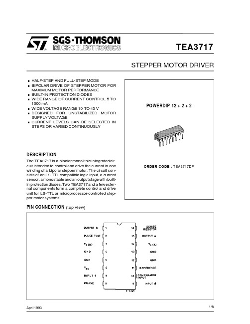
TEA3717中文资料
I0
I1
Current Level
H
H No Current
L
H Low Current
H
L Medium Current
L
L Maximum Current
PHASE − This input determines the direction of current flow in the winding, depending on the motor connections. The signal is fed through a Schmidttrigger for noise immunity, and through a time delay in order to guarantee that no short-circuit occurs in the output stage during phase-shift. High level on the PHASE-input causes the motor current flow from MA through the winding to MB.
Total Power Dissipation Io = 500mA, fs = 30kHz Io = 800mA, fs = 30kHz
Cut off Time (see figure 1 and 2, Vmm = + 10V, ton ≥ 5µs)
Turn off Delay (see figure 1 and 2, Tamb = + 25°C, dVC/dt ≥ 50mV/µs)
元器件交易网
. HALF-STEP AND FULL-STEP MODE . BIPOLAR DRIVE OF STEPPER MOTOR FOR
GL823K Datasheet
GL823KUSB 2.0 SD Card Reader ControllerDatasheetRevision HistoryTable of ContentsCHAPTER 1GENERAL DESCRIPTION (6)CHAPTER 2FEATURES (7)CHAPTER 3PIN ASSIGMENT (8)3.1SSOP16 Pinout (8)3.2Pin Description (9)CHAPTER 4BLOCK DIAGRAM (10)4.1OCCS USB PHY (10)4.2SIE (10)4.3EPFIFO (10)4.4MCU (10)4.5MHE (11)4.6Regulator (11)4.7PMOS (11)CHAPTER 5ELECTRICAL CHARACTERISTICS (12)5.1Temperature Conditions (12)5.2Operating Conditions (12)5.3DC Characteristics (12)5.4Memory Card Clock Frequency (12)5.5Maximum Ratings (13)CHAPTER 6PACKAGE DIMENSION (14)CHAPTER 7ORDERING INFORMATION (15)List of FiguresFigure 3.1 – SSOP 16 Pinout Diagram (8)Figure 6.1 – SSOP 16 Pin Package (150 mil) (14)List of TablesTable 3.1 – Pin Description (9)Table 4.1 – Functional Block Diagram (10)Table 5.1 – Temperature Conditions (12)Table 5.2 – Operating Conditions (12)Table 5.3 – DC Characteristics (12)Table 5.4 – SD/MMC Card Clock Frequency (12)Table 5.5 – Maximum Ratings (13)Table 7.1 – Ordering Information (15)CHAPTER 1GENERAL DESCRIPTIONThe GL823K is a USB 2.0 Single-LUN card reader controller which can support SD/MMC Flash Memory Cards. It supports USB 2.0 high-speed transmission to Secure Digital TM(SD), SDHC, SDXC, miniSD TM, microSD TM(T-Flash), MultiMediaCard TM (MMC), RS MultiMediaCard TM (RS MMC), MMCmicro , HS-MMC and MMCmobile. As a single chip solution for USB 2.0 flash card reader, the GL823K complies with Universal Serial Bus specification rev. 2.0, USB Storage Class Specification ver.1.0, and each flash card interface specification.The GL823K integrates a high speed 8051 microprocessor and a high efficiency hardware engine for the best data transfer performance between USB and flash card interfaces. Its pin assignment design fits to card sockets to provide easier PCB layout. Inside the chip, it integrates 5V to 3.3V regulator, 3.3V to 1.8V regulator and power MOSFETs and it enables the function of on-chip clock source (OCCS) which means no external 12MHz XTAL is needed and that effectively reduces the total BOM cost.The GL823K implements USB disconnect function; it can be used for Mobile cable/ OTG reader/ PC card reader application.CHAPTER 2FEATURES●USB specification compliance-Comply with 480Mbps Universal Serial Bus specification rev. 2.0-Comply with USB Storage Class specification rev. 1.0-Support one device address and up to four endpoints: Control (0)/Bulk Read (1)/Bulk Write (2)/Interrupt (3) ●Integrated USB building blocks-USB2.0 transceiver macro (UTM), Serial Interface Engine (SIE), Build-in power-on reset (POR) and low-voltage detector (LVD)●Embedded 8051 micro-controller-Operate @ 60 MHz clock, 12 clocks per instruction cycle-Embedded mask ROM and internal SRAM●Secure Digital TM (SD) and MultiMediaCard TM (MMC)-Supports SD specification v1.0 / v1.1 / v2.0 / SDHC (Up to 32GB)-Compatible with SDXC (Up to 2TB)-Supports MMC specification v3.x / v4.0 / v4.1 / v4.2-Supports 1 / 4 bit data bus-Compliant with Secure Digital TM v5.0●Support boost mode for SD3.0 for better performance●Support non-SD Card Detect pin, non-MS Insertion/Removal pin design to save BOM cost●Support non-SD Write Protection pin design to save BOM cost●Support LED function to indicate power and access status●On chip clock source and no need of 12MHz Crystal Clock input●On-Chip 5V to 3.3V and 3.3V to 1.8V regulators●On-Chip power MOSFET for supplying flash media card power●Support USB disconnection by memory card unplug or manual switch for Mobile cable/ OTG reader/ PCcard reader application●Available in SSOP16 package (150 mil)CHAPTER 3 PIN ASSIGMENT3.1 SSOP16 Pinout38765214D 0D 2P M O S C M D V S S D 1D 3C L KFigure 3.1 – SSOP 16 Pinout Diagram3.2Pin DescriptionTable 3.1 – Pin DescriptionNotation:Type O OutputI InputB Bi-directionalpu internal pull-up when inputpd internal pull-down when inputP Power / GroundA AnalogCHAPTER 4BLOCK DIAGRAMTable 4.1 – Functional Block Diagram4.1OCCS USB PHYThe USB 2.0 Transceiver Macrocell is the analog circuitry that handles the low level USB protocol and signaling, and shifts the clock domain of the data from the USB 2.0 rate to one that is compatible with the general logic. On chip clock source and no need of 12MHz Crystal Clock input.4.2SIEThe Serial Interface Engine, which contains the USB PID and address recognition logic, and other sequencing and state machine logic to handle USB packets and transactions.4.3EPFIFOEndpoint FIFO includes Control FIFO (FIFO0) and Bulk In/Out FIFO●EP0 FIFO FIFO of control endpoint 0. It is 64-byte FIFO and used for endpoint 0 data transfer.●Interrupt FIFO 64-byte depth FIFO of endpoint 3 for status interrupt●Bulk FIFO It can be in the TX mode or RX mode:1. It contains ping-pong FIFO (512 bytes each bank) for transmit/receive data continuously.2. It can be directly accessed by micro-controller4.4MCU8051 micro-controller inside.●8051 Core Compliant with Intel 8051 high speed micro-controller●ROM FW code on ROM●SRAM Internal RAM area for MCU access4.5MHE●MIF Media Interface: SD/MMC●MCFIFO It can access by MCU for memory card short data packet.4.6Regulator●5V to 3.3V Band Gap Regulator for stable voltage supply for USB PHY, PMOS●3.3V to 1.8V For core logic and internal memory.4.7PMOSOn-Chip power MOSFETs for memory card powerCHAPTER 5ELECTRICAL CHARACTERISTICS 5.1Temperature ConditionsTable 5.1 – Temperature Conditions5.2Operating ConditionsTable 5.2 – Operating Conditions5.3DC CharacteristicsTable 5.3 – DC Characteristics5.4Memory Card Clock FrequencyTable 5.4 – SD/MMC Card Clock Frequency5.5Maximum RatingsTable 5.5 – Maximum RatingsCHAPTER 6PACKAGE DIMENSIONInternalNo.Lot CodeDateGL823KAAAAAAAAAAYWWXXXXVersionNo.Figure 6.1 – SSOP 16 Pin Package (150 mil)CHAPTER 7ORDERING INFORMATIONTable 7.1 – Ordering Information。
KS368-TAN TITRANT产品说明说明书

KS368 - TAN TITRANTPage:1Compilation date:03/12/2014Revision date:01/01/2021Revision No:8Product name:KS368 - TAN TITRANTProduct code:AS-K23962-KWUse of substance / mixture:Oil test reagent.Company name:Parker Hannifin Manufacturing Ltd ,3 - 6 Thorgate RoadLineside Industrial EstateLittlehampton , West SussexBN17 7LU , UNITED KINGDOMUNITED KINGDOMTel:+44 (0) 1903 731470Fax:+44 (0) 1903 731480Email:Emergency tel:+32 3 575 11 30 (SGS 24/7 Emergency Hotline)Classification under CLP:Flam. Liq. 2: H225Most important adverse effects:Highly flammable liquid and vapour.Label elements:Hazard statements:H225: Highly flammable liquid and vapour.Signal words:DangerHazard pictograms:GHS02: FlamePrecautionary statements:P210: Keep away from heat, hot surfaces, sparks, open flames and other ignitionsources. No smoking.P241: Use explosion-proof electrical/ventilating/lighting equipment.KS368 - TAN TITRANTPage:2P240: Ground container and receiving equipment.P280: Wear protective gloves/protective clothing/eye protection/face protection.P303+361+353: IF ON SKIN (or hair): Take off immediately all contaminated clothing.Rinse skin with water/shower.P370+378: In case of fire: Use carbon dioxide to extinguish.Other hazards:In use, may form flammable / explosive vapour-air mixture.PBT:This product is not identified as a PBT/vPvB substance.Chemical identity:KS368 - TAN TITRANTSkin contact:Remove all contaminated clothes and footwear immediately unless stuck to skin.Drench the affected skin with running water for 10 minutes or longer if substance is stillon skin.Eye contact:Bathe the eye with running water for 15 minutes. Consult a doctor.Ingestion:Do not induce vomiting. If conscious, give half a litre of water to drink immediately.Consult a doctor.Inhalation:Remove casualty from exposure ensuring one's own safety whilst doing so. Consult adoctor.Skin contact:There may be mild irritation at the site of contact.Eye contact:There may be irritation and redness.Ingestion:There may be irritation of the throat.Inhalation:There may be a feeling of tightness in the chest with shortness of breath.Immediate / special treatment:No data available.Extinguishing media:Alcohol resistant foam. Water spray. Carbon dioxide. Dry chemical powder.Exposure hazards:Highly flammable. In combustion emits toxic fumes. Forms explosive air-vapour mixture.Vapour may travel considerable distance to source of ignition and flash back.KS368 - TAN TITRANTPage:3Advice for fire-fighters:Wear self-contained breathing apparatus. Wear protective clothing to prevent contactwith skin and eyes.Personal precautions:Refer to section 8 of SDS for personal protection details. Notify the police and firebrigade immediately. Eliminate all sources of ignition. Turn leaking containers leak-sideup to prevent the escape of liquid.Environmental precautions:Do not discharge into drains or rivers. Contain the spillage using bunding.Clean-up procedures:Do not use equipment in clean-up procedure which may produce sparks. Absorb into dryearth or sand. Clean-up should be dealt with only by qualified personnel familiar with thespecific substance.Reference to other sections:Refer to section 13 of SDS.Handling requirements:Smoking is forbidden. Use non-sparking tools. Ensure there is sufficient ventilation ofthe area. Do not handle in a confined space. Avoid the formation or spread of mists inthe air.Storage conditions:Store in a cool, well ventilated area. Keep container tightly closed. Keep away fromsources of ignition. Prevent the build up of electrostatic charge in the immediate area.Ensure lighting and electrical equipment are not a source of ignition. Storage class 3.Suitable packaging:Steel drums.Specific end use(s):No special requirement.Workplace exposure limits:No data available.DNEL / PNEC No data available.KS368 - TAN TITRANTPage:4Engineering measures:Ensure there is sufficient ventilation of the area. Ensure lighting and electricalequipment are not a source of ignition.Respiratory protection:Respiratory protection not required.Hand protection:Protective gloves. Nitrile gloves. Breakthrough time of the glove material > 1 hour. Glovesmade of thick material.Eye protection:Safety glasses. Ensure eye bath is to hand.Skin protection:Protective clothing.State:LiquidColour:ColourlessOdour:Characteristic odourEvaporation rate:ModerateOxidising:Non-oxidising (by EC criteria)Solubility in water:MiscibleAlso soluble in:Chloroform. Acetone. Diethyl ether.Viscosity:Non-viscousBoiling point/range°C:78Melting point/range°C:-130Flammability limits %: lower: 3.3upper:19Flash point°C:12Autoflammability°C:363Vapour pressure:44.6mm@20°C Relative density:0.785Other information:No data available.Reactivity:Stable under recommended transport or storage conditions.Chemical stability:Stable under normal conditions. Stable at room temperature.Hazardous reactions:Hazardous reactions will not occur under normal transport or storage conditions.Conditions to avoid:Heat. Hot surfaces. Sources of ignition. Flames.Materials to avoid:Strong oxidising agents. Strong acids.KS368 - TAN TITRANTPage:5Haz. decomp. products:In combustion emits toxic fumes.Hazardous ingredients:ETHANOLToxicity values:No data available.Skin contact:There may be mild irritation at the site of contact.Eye contact:There may be irritation and redness.Ingestion:There may be irritation of the throat.Inhalation:There may be a feeling of tightness in the chest with shortness of breath.Ecotoxicity values:No data available.Persistence and degradability:Biodegradable.Bioaccumulative potential:No bioaccumulation potential.Mobility:Readily absorbed into soil.PBT identification:This product is not identified as a PBT/vPvB substance.Other adverse effects:Negligible ecotoxicity.Disposal operations:Transfer to a suitable container and arrange for collection by specialised disposalcompany.Disposal of packaging:Dispose of in a regulated landfill site or other method for hazardous or toxic wastes.KS368 - TAN TITRANTPage:6 NB:The user's attention is drawn to the possible existence of regional or nationalregulations regarding disposal.UN number:UN1170Shipping name:ETHANOL SOLUTIONTransport class:3Packing group:IIEnvironmentally hazardous:No Marine pollutant:NoSpecial precautions:No special precautions.Specific regulations:Not applicable.Chemical safety assessment: A chemical safety assessment has not been carried out for the substance or the mixtureby the supplier.Other information:This safety data sheet is prepared in accordance with Commission Regulation (EU) No453/2010.* indicates text in the SDS which has changed since the last revision.Phrases used in s.2 and s.3:H225: Highly flammable liquid and vapour.Legal disclaimer:The above information is believed to be correct but does not purport to be all inclusiveand shall be used only as a guide. This company shall not be held liable for anydamage resulting from handling or from contact with the above product.。
史上最清晰最详细元素周期表(文字可复制非扫描版)

17
18
2 He 4.003
Helium
1s2
Oxidation States Electroneg.
–
–
Atomic Radius
–
Ionic Radius
–
Electron Affinity 1st Ion. Pot.
Unstable Anion
24.59
3 Li 6.94 4 Be 9.01
[Ne]3s1
[Ne]3s2
Atomic Number: number of protons
Oxidation States Electroneg. Oxidation States Electroneg.
1
0.93
2
1.31
Atomic Weight: weighted average of atomic masses of natural isotopes
125
(+3)62
Electron Affinity 1st Ion. Pot.
0.67
6.77
[Ar]3d54s2
Oxidation States Electroneg.
7,6,4,2,3
1.55
Atomic Radius Ionic Radius
137
(+2)67
Electron Affinity 1st Ion. Pot.
1.24
7.73
[Ar]3d104s2
Oxidation States Electroneg.
2
1.65
Atomic Radius Ionic Radius
133
(+2)74
- 1、下载文档前请自行甄别文档内容的完整性,平台不提供额外的编辑、内容补充、找答案等附加服务。
- 2、"仅部分预览"的文档,不可在线预览部分如存在完整性等问题,可反馈申请退款(可完整预览的文档不适用该条件!)。
- 3、如文档侵犯您的权益,请联系客服反馈,我们会尽快为您处理(人工客服工作时间:9:00-18:30)。
Product Name:
Tandutinib CAS No.:
387867-13-2Cat. No.:
HY-10202
Product Data Sheet
MWt:
562.70Formula:
C31H42N6O4Purity :>98%
DMSO 10mg/mL
Water
Solubility:Mechanisms:
Biological Activity:
T d ti ib (MLN518CT53518)i t t FLT3t i t ith IC50f 022M l i hibit
Pathways:Protein Tyrosine Kinase/RTK; Target:FLT3DMSO ≥10mg/mL Water <1.2mg/mL Ethanol ≥
16mg/mL
Tandutinib (MLN518, CT53518) is a potent FLT3 antagonist with IC50 of 0.22 μM, also inhibits PDGFR and c-Kit, 15 to 20-fold higher potency for FLT3 versus CSF-1R and >100-fold selectivity for
the same target versus FGFR, EGFR and KDR.
IC50 value: 0.22 uM [1]
Target: Flt3; PDGFR β; c-Kit in vitro: Tandutinib has little activity against EGFR, FGFR, KDR, InsR, Src, Abl, PKC, PKA and
MAPKs. Tandutinib inhibits IL-3-independent cell growth and FLT3-ITD autophosphorylation with an IC50 of 10-100 nM. Tandutinib also inhibits the proliferation of human leukemia Ba/F3 cells
containing FLT3-ITD mutations with IC50values of 10-30nM,and the FLT3-ITD-positive Molm-13References:
[1]. Kelly LM, et al. CT53518, a novel selective FLT3 antagonist for the treatment of acute
myelogenous leukemia (AML). Cancer Cell, 2002, 1(5), 421-432.[2]. Griswold IJ, et al. Effects of MLN518, a dual FLT3 and KIT inhibitor, on normal and malignant containing FLT3ITD mutations with IC50 values of 1030 nM, and the FLT3ITD positive Molm 13and Molm-14 cells with an IC50 of 10 nM. In FLT3-ITD-positive Molm-14 cells but not the FLT3-ITD-negative THP-1 cells, Tandutinib treatment leads to significant apoptosis by 51% and 78% at 24 and 96 hours, respecti...
hematopoiesis. Blood, 2004, 104(9), 2912-2918.[3]. Schittenhelm MM, et al. The FLT3 inhibitor tandutinib (formerly MLN518) has sequence-independent synergistic effects with cytarabine and daunorubicin. Cell Cycle, 2009, 8(16), 2621-
2630.Caution: Not fully tested. For research purposes only
Medchemexpress LLC
18 W i l k i n s o n W a y , P r i n c e t o n , N J 08540,U S A
E m a i l : i n f o @m e d c h e m e x p r e s s .c o m W e b : w w w .m e d c h e m e x p r e s s .c o m。