ANSI-ASME B1-20-1 Pipe Threads General Purpose (1992 31p)
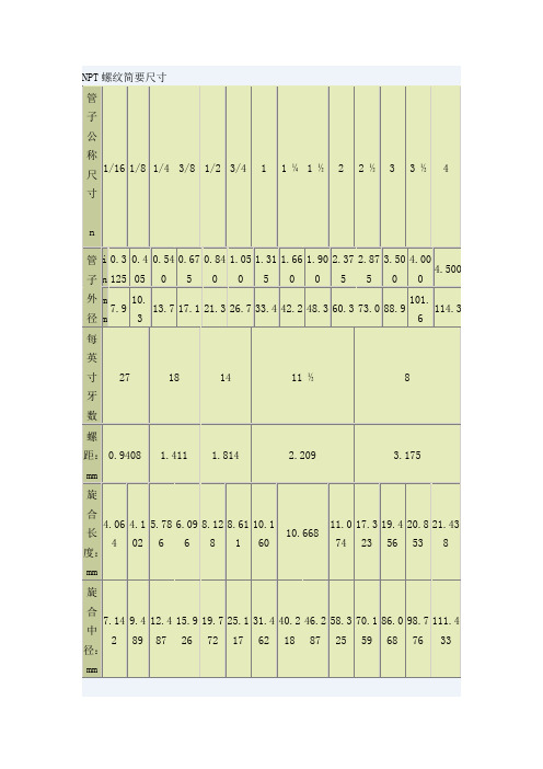
NPTF螺纹标准[1]
![NPTF螺纹标准[1]](https://img.taocdn.com/s3/m/1cdd350af12d2af90242e62d.png)
NPT,PT,G都是管螺纹.NPT 是National (American) Pipe Thread 的缩写,属于美国标准的60 度锥管螺纹,用于北美地区.国家标准可查阅GB/T12716-1991PT 是Pipe Thread 的缩写,是55 度密封圆锥管螺纹,属惠氏螺纹家族,多用于欧洲及英联邦国家.常用于水及煤气管行业,锥度规定为1:16.国家标准可查阅GB/T730 6-2000G 是55 度非螺纹密封管螺纹,属惠氏螺纹家族.标记为G 代表圆柱螺纹.国家标准可查阅GB/T7307-2001另外螺纹中的1/4、1/2、1/8 标记是指螺纹尺寸的直径,单位是英吋.行内人通常用分来称呼螺纹尺寸,一吋等于8分,1/4 吋就是2分,如此类推.G 就是管螺纹的统称(Guan),55,60度的划分属于功能性的,俗称管圆。
即螺纹由一圆柱面加工而成。
ZG俗称管锥,即螺纹由一圆锥面加工而成,一般的水管接头都是这样的,国标标注为Rc公制螺纹用螺距来表示,美英制螺纹用每英寸内的螺纹牙数来表示,这是它们最大的区别,公制螺纹是60度等边牙型,英制螺纹是等腰55度牙型,美制螺纹60度。
公制螺纹用公制单位,美英制螺纹用英制单位。
管螺纹主要用来进行管道的连接,其内外螺纹的配合紧密,有直管与锥管两种。
公称直径是指所连接的管道直径,显然螺纹直径比公称直径大。
1/4,1/2,1/8是英制螺纹的公称直径,单位是英寸。
、从设计角度来说,螺纹副旋合后,在基面距内应形成无隙结合。
实际上各直径、牙型角、螺距和锥角在制造中都有偏差。
NPT螺纹的牙顶和牙底为过渡配合,仅靠板紧螺纹副时的微量变形来达到100%的无隙量是不可能的。
为了确保其密封性能,往往需要螺纹副内加一定的密封介质,它主要适应于中低压系统。
NPTF螺纹的牙顶和牙底为过盈配合,扳紧螺纹副后,窄平的牙底迫使尖的牙顶弹塑性变形,因而获得100%的过盈配合,无需密封介质即能阻止泄漏,适于高压系统大径、小径不同NPTF螺纹与NPT螺纹的螺距P、基面距L1、基面上的中径d2均相同,大径、小径的计算方法也相同,但因两者牙高不同,所以大径小径并不相同。
ASME__B1.20.1-2006(中文版)

美国国家标准管螺纹通用标准(单位:英寸)ANSI/ASME B1.20.1 - 1983(根据ANSI 82.1-1968版修订并重新制定)1992年重审通用委员会专用请参阅ASME手册(美国机械工程师协会手册) AS-112001年重审通用委员会专用2006年重审通用委员会专用美国机械工程师学会赞助出版地址:联合工程中心345东47街纽约州,N.Y邮编:10017验收通知本文件为非政府文件,于1984年10月25日通过并由联邦机构核准使用。
这里显示产业集团提供了通关所需要的现行法规。
该文件的副本由国防部标准化资料管理中心、海军出版物和位于PA 19120费城的表格中心收藏,正式版本的发行仅用于国防部活动。
承包商和产业集团必须直接从以下机构获得副本:美国机械工程师学会(345东47街纽约10017-345 East 47th Street New York, New York 10017)或美国国家标准学会(1430百老汇纽约10018-1430 Broadway New York, New York 10018)。
文件名称:通用管螺纹(英寸)具体发布时间:1983年4月发布单位:美国机械工程师学会注意事项:联邦机构使用本标准时,须遵循联邦事务第7条螺纹标准FED-STD-H28/7中通用管螺纹的所有要求和限制。
注意事项:当对本标准的重申,修订,修改或取消最初提出时,工业集团应为本标准负责,并通知军方协调活动或通知被提议的变更,并要求其参与。
管理者:民间机构间的协调活动:陆军-AR 商业-国家商务部审查—FPI海军-AS 运输部—ACO, APM, FAA, FRA, NHT空军-11 NASA(国家航空和宇宙航天局)—JFK, LRC, MSF总务管理局—FSS,PCD 美国农业部—AFS住房和城市发展部—HCC评审活动:海军-YD 陆军-AT, GL, ME, MI军事协调活动:国防后勤局-IS (工程THDS-0052)发行日期:1983年8月31日本守则或标准是按公认程序进行开发的,符合美国国家标准。
ASTMANSIASME三者区别

ASTM ANSI ASME 三者区别各位老大,请赐教:这三者在管路管路附件上选择有没有什么区别?也就是说我怎么选择美标管路附件的标准?应该选择那个标准?回答1ASTM 是美国材料标准,类似于国内的GB713ANSI是法兰标准,类似于国内的HG20615ASME是设计规范,但由于ASME是一个完整的体系,所以将ASTM和ANSI分别纳入其中比如SA516-70 ASMEB16.5回答2三个不同机构而已,就好像国内有化工部HG,国标GB,石化SH等。
回答3ASME 美国机械工程师学会标准ASTM 美国材料与试验协会标准ANSI 美国国家标准三个不同的标准化组织,每个标准都自成体系。
是美标系统中影响和应用最大的。
其中ASME标准与ANSI标准涵盖了绝大部分工业领域,包括材料、加工、工艺、试验等等方面。
ASME引用了许多ANSI和ASTM的标准,对于管道、管路附件,这三者基本是统一的,俗称美标管道、管件、管路附件(法兰,垫片等等),采用最多的是ASME/ANSI标准。
回答4ASME不做具体工作,实验和制定工作几乎都由ANSI和ASTM完成,ASME只认可其中规范为自己所用,所以经常看到重复的标准号,实际是一样的内容.回答5他们各自的组织的性质和功能不同,侧重点也不一样。
ASTM 是负责对各类新旧材料制定和重新制定标准。
因为它是测试和材料协会。
ASME则是选择性地吸收和筛选这些个标准为相关的工程所用,并加以修正改良。
因为他们是工程师。
据我老人家所知,ASME本身并没有自己的材料标准。
这就是为什么多数工程的材料都必需是ASME批准的。
而这些标准当然是建立在材料协会原有的标准上的。
ASTM 材料标准与ASME材料标准的区别ASTM材料标准是美国材料与试验协会制定的标准,而ASME是美国机械工程师协会的标准;ASTM材料经ASME认可可用于承压设备后就成为ASME材料,ASME材料标准大部分都是引用ASTM的。
ANSI B1.20.1标准

NPT- National Pipe Taper Threads - ANSI B1.20.1国家螺纹管标准ANSI B1.20.1Characteristics of NPT (also known as ANSI/ASME B1.20.1 Pipe Threads, General Purpose):该标准规定:tapered thread 1o 47' 锥形螺纹1度47分truncation of roots and crests are flat 顶部和根部的截断面是平的60o thread angle 60度的螺纹断面角pitch is measured in threads per inch 单位罗纹数以每英寸计算Note! Pipe sizes do not refer to any physical dimensions. The outside diameter of a pipe or fitting must be measured and compared to a table for size identification. A 3/4" NPT pipe thread has an outside diameter - OD - of 1.050 inches.备注:管的尺寸不是指物理容积。
管的外部直径和属性必须以下面这个表格来确定。
例如:一个标准为3/4" NPT的管外部直径为1.050英寸。
Each thread size has a defined number of threads per inch - TPI, or pitch. The 3/4" NPT pipe thread has 14 threads per inch. Both the TPI and OD of the thread are required for positive identification of thread size because more than one size have the same TPI.每种罗纹管每英寸有固定的罗纹数(单位的罗纹数)。
贝壶欧丹 戴维LNG设施技术交付条款说明书

Bayu Undan / Darwin LNG FacilitiesTechnical Delivery Terms1 SCOPEThis document outlines the general technical requirements for the supply of generic Pressure and Temperature Instrumentation for the Santos Bayu-Undan and Darwin LNG Facilities.Specifically, Pressure and Temperature Transmitters shall be manufactured under the general requirements of the following codes and standards:AS/NZS 60079.0:2005Electrical Apparatus for Explosive Gas Atmosphere – General Requirements AS/NZS 60079.1:2005Electrical Apparatus for Explosive Gas Atmosphere – Flameproof AS/NZS 60079.10:2004Electrical Apparatus for Explosive Gas Atmosphere – Classification of Hazardous Areas AS 60529:2004Degrees of Protection Provided by Enclosures (IP Code) API RP 551:1993Process Measurement Instrumentation API RP 554:1995Process Instrumentation and Control ANSI NC96.1Temperature Instruments - Thermocouples ANSI/ASME B1.20.1Pipe Thread General Purpose (Covering NPT Threads) ASME PTC 19.3Thermowell Wake Frequency Calculations IEC 801Electro-magnetic Compatibility for Industrial-Process Measurement and Control Equipment NACE MR0175Sulfide Stress Cracking Resistant Metallic Materials for Oilfield Equipment NAMUR Recommendation 43Material Description:Generic Pressure and Temperature Transmitters Doc No: TDT 09Rev: 1 Prepared By: B.Carey Date:26 September 2008 Checked By: C Perham DOC CON Ref: ALL/CMP/SPE/009Approved By: P. Rogers2 EXCEPTIONS AND ADDITIONAL REQUIREMENTS∙Instruments and enclosures shall not contain mercury, beryllium or asbestos.∙The materials of construction for instrument bodies and electronic housings is 316SS, although suitable alternatives including filled polymer based materials, and high-grade epoxy coated metals (including marine grade aluminium and steel) may be considered. Copper or zinc-based alloys shall not be used. Protection of steel by plating or galvanizing alone is not adequate. Instrument enclosures exposed to outdoor environments shall be ingress protected to IP56 or higher∙304 stainless steel shall not be used for any parts or equipment∙All electronic components and boards shall be “tropicalised” using a silicone encapsulation treatment or equivalent.∙Instrumentation to be designed to handle the following ambient and plant conditions: ▪Maximum ambient temperature 38 deg C▪Minimum ambient temperature 10 deg C▪Relative Humidity 100%∙Unless otherwise specified, all brackets, fixings, bolts, nuts, and washers for mounting and securing instrumentation shall be 316SS. Bolting shall be suitably rated for containment ofpressure retaining components and secured using lock washer, nut or loctite.∙Where required on the data sheets, all wetted materials shall comply with the requirements of NACE MR0175.∙All instrumentation and glands shall be suitable for Class I, Zone 1, Group IIA, temperature class T3; as a minimum.∙All electrical equipment for use in these hazardous areas shall be certified and approved for use in the area concerned by Standards Australia (SAA). Where SAA certification or approval is not available, IECEx certified equipment is acceptable. Equipment supplied with other test house certification shall be subject to Purchaser scrutiny and approval.∙All instrumentation shall have its tag/identification number and service description engraved on a 316SS label. Label details are as follows:▪Label size 90x35mm▪Tag Number text size 10mm▪Service description text size 5mm▪Details of tag number and service description can be found on the instrument data sheet ∙Tag/ID plates shall be attached to the equipment using stainless steel wire.∙Manufacturer’s standard nameplates may be used, subject to Principal approval.∙Transmitters shall have calibration stability warranted for a minimum of two years.∙Transmitter capsule materials shall be Hastelloy ‘C’.∙Pressure transmitters shall be suitable for direct threaded type mounting.∙Transmitters shall be supplied with 2-inch pipe stand mounting brackets for DLNG and no bracket for Bayu Undan. For Bayu Undan transmitters, support shall be provided from the valve manifold and its bracket assembly.∙Provisions shall be made for single point connections to the transmitter assemblies as follows:▪20 mm ISO electrical entry connection for all transmitters.▪½ inch NPT Male process connection(s) for pressure transmitters only▪Traditional flange connection for differential pressure transmitters only (ie. suitable for direct coupling to the associated manifold).▪Spare cable entries shall be covered with a 316 SS plug (plug to be certified Exd).∙Vent and drain ports are required on the transmitter body.∙NPT thread connections shall conform to ANSI/ASME B1.20.1 with the following exceptions:▪Gauging External Taper Threads with Ring Gauge (Male Threads ): When hand tight, the male fitting must engage into the ring gauge -0 to +1 turn more than the start of thefirst scratch mark on the chamfer zone.▪Gauging Internal Threads with Plug Gauge (Female Threads): When hand tight, the plug gauge must engage into the female fitting -0 to +1 turn below the last threadscratch on the chamfer zone.▪This will ensure a minimum engagement of 4 threads by hand pressure. Four turns will also be expected for wrench tightness, including application of PTFE tape orequivalent.▪If fittings are supplied that do not meet the above requirement, then the Supplier must guarantee that the thread engagement of 4 turns, including wrench tightness asdescribed above, will be achieved on all fittings. Any fittings/threads that do not meetthis requirement will be replaced at no cost to the Principal.∙Instruments, wherever possible, shall be of the manufacturer's standard type, using charts and scales of standard ranges.∙All instruments shall be calibrated in factory and the supplier shall provide calibration certification. One copy of the calibration certificate shall be shipped with instruments.∙All instruments shall be capable of being field calibrated without being disconnected from the process.∙Units of Measurement - Pressure▪Static Pressure Bar Gauge▪Low Range Static Pressure Bar Absolute▪Vacuum Bar Absolute▪Compound Pressure Bar Absolute▪Absolute Pressure Bar Absolute.▪Differential Pressure Bar∙Units of Measurment – Temperature – degrees Celcius∙RTD's shall be platinum, 100 ohm at 0°C detectors. The temperature coefficient of the RTD's shall be 0.00385 ohm/°C. Three wire elements shall be used as a minimum.∙Thermocouple type selection shall be in accordance with the instrument data sheet and/or process conditions.∙Thermocouples and RTD's shall be spring loaded into the thermowell to minimize the transfer lag. ∙Thermocouples and RTD's shall be sheathed with magnesium-oxide insulation. The sheath shall be 316 stainless steel and 0.250" OD. Conductors shall be 1.00mm² (#18 AWG). Thethermocouple element shall be insulated (non grounded) from the element sheath.∙The RTD transmitters shall be all electronic, two-wire units with a selectable digital/4-20 mA DC output. The unit shall accept a 3-wire 100-ohm platinum resistance sensor and provide alinearized output. Zero and span adjustability is required. Screw terminals are required for wiring termination.∙Thermocouple transmitters shall be all electronic, two-wire units with a selectable digital/4-20 mADC output (depending on data sheet requirements). The unit shall accept a thermocouple input and provide an output linearized to the thermocouple voltage signal. Zero and span adjust-ability, cold junction compensation and burnout protection are required. Screw terminals are required for wiring terminations. Burnout indication shall normally be upscale but some special and lowtemperature applications will require downscale indication.∙Analog signals, other than thermocouple signals shall be digital (HART protocol) or 4-20 mADC (selectable – depending on datasheet requirements). For DLNG DCS application the transmitter shall be capable of providing a Honeywell DE signal (specified on the instrument data sheet if required). A two-wire system shall be used, when they are available. Electronic instrumentsystems shall use a digital or 4-20 mADC signal for transmission and 4-20 mADC for control.Discrete signals shall be 24 volt DC. Unless specified otherwise, alarm, shutdown, and ON/OFF control signals shall be 24 volt DC.∙Transmitters shall be compliant to Namur NE43. Output signals shall be limited to between3.8mA and 20.5mA.3 CERTIFICATION AND DOCUMENTATIONAll transmitters shall be supplied with the following certification as a minimum:∙Hazardous Area Certificate of Conformance∙Material traceability certificates for wetted components∙Pressure Test Certification (Pressure Transmitters)∙Instrument Factory Calibration CertificateDocumentation to be supplied with each transmitter:∙Installation, Operating, Maintenance Manual/User Guide∙Certification as described above。
美国标准管螺纹(National Pipe Tapered)
NPT代表美国标准管螺纹(National Pipe Tapered) ,NPTF则是干密封式美国标准管螺纹。
两者基本牙型是一样的,不同点是:∙螺纹牙高不一样。
NPT可能有过盈也可能有间隙,但NPTF没有间隙;∙NPT内外螺纹均为圆锥,而NPTF外螺纹是圆锥,内螺纹则有圆锥、圆柱两种;∙NPT有右旋也有左旋,NPTF只有右旋一种旋向。
NPTF NPTM螺纹是什么意思?NPT:National (American) Pipe Thread美国管螺纹。
F:Female内螺纹。
M:Male外螺纹。
国家螺纹管标准ANSI B1.20.1Characteristics of NPT (also known as ANSI/ASME B1.20.1 Pipe Threads, General Purpose):该标准规定:tapered thread 1o 47' 锥形螺纹1度47分truncation of roots and crests are flat 顶部和根部的截断面是平的60o thread angle 60度的螺纹断面角pitch is measured in threads per inch 单位罗纹数以每英寸计算Note! Pipe sizes do not refer to any physical dimensions. The outside diameter of a pipe or fitting must be measured and compared to a table for size identification. A 3/4" NPT pipe thread has an outside diameter - OD - of 1.050 inches.备注:管的尺寸不是指物理容积。
管的外部直径和属性必须以下面这个表格来确定。
例如:一个标准为3/4" NPT的管外部直径为1.050英寸。
ASME中国制造-ASME B1.20.2M-2006 一般用途用60℃管螺纹

Pipe Threads, 60 deg, General PurposeA N A M E R I C A N N A T I O N A L S T A N D A R DPipe Threads, 60deg, General Purpose A N A M E R I C A N N A T I O N A L S T A N D A R DThree Park Avenue • New York, NY 10016Date of Issuance:June15,2007This Standard will be revised when the Society approves the issuance of a new edition.There will be no addenda or written interpretations of the requirements of this Standard issued to this edition. Periodically,certain actions of the ASME B1Committee may be published as Cases.Cases are published on the ASME Web site under the Committee Pages at as they are issued.ASME is the registered trademark of The American Society of Mechanical Engineers.This code or standard was developed under procedures accredited as meeting the criteria for American National Standards.The Standards Committee that approved the code or standard was balanced to assure that individuals from competent and concerned interests have had an opportunity to participate.The proposed code or standard was made available for public review and comment that provides an opportunity for additional public input from industry,academia, regulatory agencies,and the public-at-large.ASME does not“approve,”“rate,”or“endorse”any item,construction,proprietary device,or activity.ASME does not take any position with respect to the validity of any patent rights asserted in connection with any items mentioned in this document,and does not undertake to insure anyone utilizing a standard against liability for infringement of any applicable letters patent,nor assumes any such ers of a code or standard are expressly advised that determination of the validity of any such patent rights,and the risk of infringement of such rights,is entirely their own responsibility.Participation by federal agency representative(s)or person(s)affiliated with industry is not to be interpreted as government or industry endorsement of this code or standard.ASME accepts responsibility for only those interpretations of this document issued in accordance with the established ASME procedures and policies,which precludes the issuance of interpretations by individuals.No part of this document may be reproduced in any form,in an electronic retrieval system or otherwise,without the prior written permission of the publisher.The American Society of Mechanical EngineersThree Park Avenue,New York,NY10016-5990Copyright©2007byTHE AMERICAN SOCIETY OF MECHANICAL ENGINEERSAll rights reservedPrinted in U.S.A.CONTENTSForeword (iv)Committee Roster (v)Correspondence With the B1Committee (vi)1Scope (1)2Reference and Symbols (1)3Taper Pipe Thread Form (1)4Specifications for General Purpose Taper Pipe Threads,NPT (8)5Specifications for Internal Parallel Threads in Pipe Couplings,NPSC (8)6Gauges and Gauge Tolerances for Standard Pipe Thread,NPT (8)7Gauging of Taper Pipe Thread,NPT (11)8Gauging of NPSC Parallel Pipe Threads (11)Figures1Standard Taper Pipe Thread Notation (2)2Basic Profile of Standard Taper Pipe Thread (3)3Standard Taper Pipe Threads for Pressure-Tight Joints (5)4NPT Standard Taper Pipe Thread Plug and Ring Gauges (12)5Suggested Form of Gauge Thread (12)6Gauging External Taper Threads With Ring Gauge (12)7Gauging Internal Taper Threads With Plug Gauge (12)8Gauging of Chamfered Threads (18)Tables1Limits on Crest and Root Truncation of Standard External and InternalTaper Pipe Threads (4)2Basic Thread Dimensions (6)3Tolerances on Taper,Lead,and Angle of Pipe Threads,NPT (9)4Dimensions,Internal Parallel Threads in Pipe Couplings,NPSC (9)5Basic Dimensions of Plug and Ring Gauges for NPT Threads (13)6Tolerances for NPT Working Plug and Ring Gauges (14)7Diameter Equivalent of Variation in Lead for Tools and Gauges (16)8Diameter Equivalent of Variation in Half Included Angle of Thread forTools and Gauges (17)Nonmandatory AppendicesA The Turns of Engagement Method of Verifying Product Threads (19)B Tap Drill Sizes (20)iiiFOREWORDThis Standard is a metric conversion of the data for NPT inch series taper pipe threads and NPSC inch series straight internal pipe threads.The NPT and NPSC inch threads are included in ANSI/ASME B1.20.1,Pipe Threads,General Purpose(Inch).Threads and gages delineated herein are interchangeable with those in ANSI/ASME B1.20.1.Tabulated metric values have been converted from values in ANSI/ASME B1.20.1and rounded in accordance with ASME B1.30, Screw Threads:Standard Practice for Calculating and Rounding Dimensions.Values are given in millimeters.When compared to values calculated from formulas in this Standard,there may be a difference in the last decimal place but this will not affect interchangeability.The ASME B1Subcommittee20 prepared this metric Standard in order to encourage global use of the NPT Pipe Thread.For ease of use,both product threads and gauging are contained in this one Standard.Nonmandatory Appendices A and B are informative only and are not considered a part of this Standard. ASME B1.20.2M was approved by the American National Standards Institute on December 21,2006.ivASME B1COMMITTEEStandardization and Unification of Screw Threads(The following is the roster of the Committee at the time of approval of this Standard.)STANDARDS COMMITTEE OFFICERSA.L.Barrows,Chair D.S.George,Vice Chair A.L.Guzman,SecretarySTANDARDS COMMITTEE PERSONNELA.L.Barrows,Kennametal–IPGF.G.Calderone,Corresponding Member,Quality Systems ImplementersR.Dodge,Pennoyer-Dodge Co.D.Everett,National Institute of Standards and Technology G.A.Flannery,Corresponding Member,Mercury Gage Co.H.N.Frost,Defense Supply Center Philadelphia J.O.Gehret III,Vermont Thread Gage D.S.George,Ford Motor Co.J.R.Gervasi,Kerr Lakeside,Inc.J.Greenslade,Greenslade and Co.L.C.Borowski,Alternate,Greenslade and Co.A.L.Guzman,The American Society of Mechanical Engineers R.J.Hukari,SPS TechnologiesL.C.Johnson,The Johnson Gage Co.D.D.Katz,Precision Fittings R.P .Knittel,Leitech-US Ltd.P rouche,Swanson Tool Manufacturing Co.SUBCOMMITTEE 20—PIPE THREADSD.D.Katz,Chair,Precision Fittings K.Bly,Hemco GagesM.Hop,Alternate,Hemco GagesF.G.Calderone,Corresponding Member,Quality Systems ImplementerJ.A.Casner,Corresponding Member,Casner Engineering Services M.Cox,Corresponding Member,Frank J.Cox Sales,Ltd.R.Dodge,Pennoyer-Dodge Co.G.A.Flannery,Corresponding Member,Mercury Gage Co.D.D.Gajdosik,Besly Products Corp.J.O.Gehret III,Vermont Thread Gage J.R.Gervasi,Kerr Lakeside,Inc.J.A.Gruber,Wheatland Tube Co.L.C.Johnson,The Johnson Gage Co.vrzelere,Corresponding Member,Deltronic Corp.L.L.Lord,Corresponding Member,Caterpillar,Inc.M.H.McWilliams,PMC Lonestar D.Miskinis,Kennametal–IPGW.R.Newman,Corresponding Member,Consultant D.R.Oas,Seaway Bolt and Specials Corp.M.W.Rose,Glastonbury Southern GageW.A.Watts,Alternate,Glastonbury Southern Gage E.Schwartz,ConsultantR.H.Searr,Member Emeritus,Mak Tool and Gage B.F.Sheffler,Dresser-Rand Co.A.D.Shepherd,Jr.,Emuge Corp.D.Skierski,Sterling Gage and Calibration LLC R.D.Strong,General Motors Corp.A.F.Thibodeau,Member Emeritus,Swanson Tool Manufacturing Co.R.E.Vincent,Jr.,General Plug Manufacturing Co.C.J.Wilson,Industrial Fasteners InstituteR.P .Knittel,Leitech–US Ltd.P rouche,Swanson Tool Manufacturing rzelere,Corresponding Member,Deltronic Corp.M.H.McWilliams,PMC Lone StarD.R.Maisch,Alternate,PMC Lone Star D.R.Oas,Seaway Bolt and Specials Corp.J.R.Popovic,Cleveland Specialty Inspection Services M.W.Rose,Glastonbury Southern GageR.H.Searr,Corresponding Member,Consultant A.D.Shepherd,Jr.,Emuge Corp.D.Skierski,Sterling Gage and Calibration LLCA.F.Thibodeau,Corresponding Member,Swanson Tool Manufacturing Co.R.E.Vincent,Jr.,General Plug Manufacturing Co.CORRESPONDENCE WITH THE B1COMMITTEE General.ASME Standards are developed and maintained with the intent to represent the consensus of concerned interests.As such,users of this Standard may interact with the Committee by requesting interpretations,proposing revisions,and attending Committee meetings.Corre-spondence should be addressed to:Secretary,B1Standards CommitteeThe American Society of Mechanical EngineersThree Park AvenueNew York,NY10016-5990Proposing Revisions.Revisions are made periodically to the Standard to incorporate changes that appear necessary or desirable,as demonstrated by the experience gained from the application of the Standard.Approved revisions will be published periodically.The Committee welcomes proposals for revisions to this Standard.Such proposals should be as specific as possible,citing the paragraph number(s),the proposed wording,and a detailed description of the reasons for the proposal,including any pertinent documentation. Proposing a Case.Cases may be issued for the purpose of providing alternative rules when justified,to permit early implementation of an approved revision when the need is urgent,or to provide rules not covered by existing provisions.Cases are effective immediately upon ASME approval and shall be posted on the ASME Committee Web page.Requests for Cases shall provide a Statement of Need and Background Information.The request should identify the standard,the paragraph,figure or table number(s),and be written as a Question and Reply in the same format as existing Cases.Requests for Cases should also indicate the applicable edition(s)of the standard to which the proposed Case applies.Attending Committee Meetings.The B1Standards Committee regularly holds meetings,which are open to the public.Persons wishing to attend any meeting should contact the Secretary of the B1Standards Committee.viASME B1.20.2M-2006PIPE THREADS,60deg,GENERAL PURPOSE1SCOPEThis Standard specifies the designations,dimensions, and tolerances and establishes a verification system for 60deg included angle pipe threads.It is applicable for general purpose pipe and fitting connections.Where pressure-tight joints are required,it is intended that taper pipe threads conforming to this Standard be made up wrench-tight with a sealant.To prevent galling on certain piping materials such as stainless steel,the seal-ant should contain a lubricant.Internal parallel(straight)pipe threads,series NPSC, are used with external taper pipe threads,series NPT. Internal taper pipe threads,series NPT,are used with external taper pipe threads,series NPT.2REFERENCE AND SYMBOLS2.1Reference StandardThe following publication is referenced in this Stan-dard.The latest edition shall apply.ASME B1.20.1,Pipe Threads,General Purpose(Inch) Publisher:The American Society of Mechanical Engineers(ASME),Three Park Avenue,New York, NY10016-5900;Order Department:22Law Drive, P.O.Box2300,Fairfield,NJ07007-23002.2SymbolsThe following symbols are used(see Fig.1):D p outside diameter of pipeE0p basic pitch diameter at small end of external thread(or end of pipe)E1p basic pitch diameter at plane of hand-tight engagement length(L1),external thread,largeend of internal threadE2p basic pitch diameter at plane of effective thread length(L2),external threadE3p basic pitch diameter at plane of wrench-tight engagementE5p basic pitch diameter at L5K0p basic minor diameter at small end of external thread(or end of pipe)L1p length of hand-tight engagement between internal and external threadsL2p length of effective thread,external threadL3p length of thread beyond L1allowing wrench-tight engagement,internal thread;alsowrench makeup1L4p overall length of thread,including vanish thread,external threadL5p length of complete threads,external thread V p vanish thread(s),allowance for chamfer on tool-ing or other process of thread production3TAPER PIPE THREAD FORM3.1Thread ProfileThe form of thread profile specified in this Standard shall be known as the Standard Taper Pipe Thread Form. The relations as specified herein for form of thread and general notation are shown in Fig.2.3.2Angle of ThreadThe angle between the sides of the thread is60deg when measured in an axial plane.The line bisecting this angle is perpendicular to the axis.3.3Truncation and Thread HeightThe height,H,of the sharp V thread isH p0,866025PwhereP p pitch of threadThe basic maximum height of the truncated thread,h, (see Fig.2)is based on factors entering into the manufac-ture of cutting tools and the making of tight joints.Maximum h p0,800000PThe crest and root of pipe threads are truncated a minimum of0,033000P.The maximum depth of trunca-tion for the crest and root of these pipe threads will be found in Table1.The crest and roots of external and internal threads may be truncated either parallel to the pitch line or parallel to the axis.The illustration in Fig.2,giving a sectional view of this standard thread form,represents the truncated thread form by a straight line.However,when closely examined,the crests and roots of commercially manufac-tured pipe threads appear slightly rounded.When crests and roots of threading tools or chasers lie within the limits shown in Table1,the pipe threads of products produced by such means are acceptable on the basis of in-process control.NotationFig.1Standard Taper Pipe ThreadD 305122ASME B1.20.2M-2006Fig.2Basic Profile of Standard Taper PipeThreadInternal ThreadExternal ThreadwhereF c p width of flat at crest F r p width of flat at rootf c p depth of truncation at crest f r p depth of truncation at rootH p 0,866025P p height of 60deg sharp V thread h p 0,800000P p height of thread on product n p number of threads per 25,4mmP p 25,4/n p pitch (measured parallel to axis)␣p 30deg p thread flank angle p 1°47′p thread taper per sideGENERAL NOTE:For a symmetrical parallel screw thread,H p 25,4(cot ␣)/2n .For a symmetrical taper screw thread,the exact value for Standard taper pipe thread is H p 0,865743P .For a 3,175mm pitch thread,which is the coarsest standard taper pipe thread pitch,the corresponding values of H are 2,74873and 2,74963,the difference being 0,00090mm.This difference being too small to be significant,the value of H p 0,866025P continues in use for threads of 1⁄16taper on the diameter.3ASME B1.20.2M-2006T a b l e 1L i m i t s o n C r e s t a n d R o o t T r u n c a t i o n o f S t a n d a r d E x t e r n a l a n d I n t e r n a l T a p e r P i p e T h r e a d sI n t e r n a l T h r e a dE x t e r n a l T h r e a dH e i g h t o f H e i g h t N u m b e r S h a r p V T r u n c a t i o n ,fE q u i v a l e n t W i d t h o fF l a t ,Fo f T h r e a d ,o f T h r e a d s ,T h r e a d ,h ,m m M i n i m u mM a x i m u mT o l e r a n c eM i n i m u mM a x i m u mT o l e r a n c en ,H ,p e r 25,4m mm mM a x .M i n .F o r m u l am m F o r m u l a m mm mF o r m u l am mF o r m u l am mm m1234567891011121314270,814830,7530,6340,033P 0,0300,096P 0,0910,0610,038P 0,0360,111P 0,1040,068181,221991,1290,9740,033P 0,0460,088P 0,1240,0790,038P 0,0530,102P 0,1450,092141,571241,4511,2880,033P 0,0610,078P 0,1420,0810,038P 0,0690,090P 0,1630,09411,51,912871,7671,5900,033P 0,0740,073P 0,1600,0860,038P 0,0840,084P 0,1850,10182,749552,5402,3560,033P 0,1040,062P0,1980,0940,038P0,1220,072P0,2290,107G E N E R A L N O T E :T h e b a s i c d i m e n s i o n s o f t h e S t a n d a r d T a p e r P i p e T h r e a d a r e g i v e n i n m i l l i m e t e r s t o t h r e e ,f o u r ,a n d f i v e d e c i m a l p l a c e s .W h i l e t h i s i m p l i e s a g r e a t e r d e g r e e o f p r e c i s i o n t h a n i s o r d i n a r i l y a t t a i n e d ,t h e s e d i m e n s i o n s a r e s o e x p r e s s e d f o r t h e p u r p o s e o f e l i m i n a t i n g e r r o r s i n c o m p u t a t i o n s .4ASME B1.20.2M-2006Fig.3Standard Taper Pipe Threads for Pressure-TightJointsInternal ThreadExternal Thread5ASME B1.20.2M-2006T a b l e 2B a s i c T h r e a d D i m e n s i o ns6ASME B1.20.2M-2006T a b l e 2B a s i c T h r e a d D i m e n s i o n s (C o n t ’d )N o m .P i t c h C o m p l e t e B a s i c N u m b e r D i a m .,O v e r a l l H a n d -t i g h t E f f e c t i v e T h r e a d ,E x t e r n a l M i n o r W r e n c h M a k e u p L e n g t h N o m .o f a t L e n g t h E n g a g e m e n t E x t e r n a l T h r e a d s L e n g t h ,L 1D i a m .C h a n g e i n f o r I n t e r n a l T h r e a dO .D .T h r e a d s ,B e g i n -o f [N o t e (5)]L e n g t h ,L e n g t h ,P l a n e t o L 2a t S m a l l D i a m ./o f n ,P i t c h n i n g o fP i t c h P i t c h E x t e r n a l H e i g h t L 1L 2P l a n e ,E x t e r n a l L e n g t h V a r n i s h L e n g t h ,D i a m .,E n d o f T h r e a d N o m .P i p e ,p e r o f E x t e r n a l D i a m .P i t c h D i a m .,T h r e a d ,o f [N o t e (1)][N o t e (3)]T h r e a d (L 2−L 1)L 3T h r e a d ,V L 5E 5P i p e ,K 0(0,0625/n )P i p e D ,25,4T h r e a d ,T h r e a d ,[N o t e (2)]D i a m .,E 3,L 4,m m T h r e a d ,S i z e m m m m P E 0m mT h r e a d s E 1m m T h r e a d s E 2m mT h r e a d s m m T h r e a d s m m m m T h r e a d s [N o t e (4)]m m m m h m m m m1234567891011121314151617181920212223241⁄167,9270,9416,8884,0644,327,1426,6327,057,3032,5682,732,82236,7123,2643,479,8964,7507,1850,7536,1370,0591⁄810,3270,9419,2334,1024,369,4896,7037,129,6522,6012,762,82239,0573,2643,479,9674,8219,5340,7538,4810,0591⁄413,7181,41112,1265,7864,1012,48710,2067,2312,7644,4203,134,234311,8614,8973,4715,1037,38412,5871,12910,9960,0883⁄817,1181,41115,5456,0964,3215,92610,3587,3416,1934,2623,024,234315,2814,8973,4715,2557,53616,0161,12914,4170,0881⁄221,3141,81419,2648,1284,4819,77213,5567,4720,1115,4282,995,443318,9246,2943,4719,8509,92919,8851,45117,8130,1133⁄426,7141,81424,5798,6114,7525,11713,8617,6425,4455,2502,895,443324,2396,2943,4720,15510,23425,2191,45123,1270,113133,411,52,20930,82610,1604,6031,46117,3437,8531,9107,1833,256,627330,4127,6633,4725,00612,92631,6341,76729,0600,13811⁄442,211,52,20939,55110,6684,8340,21817,9538,1340,6737,2853,306,627339,1377,6633,4725,61613,53640,3971,76737,7850,13811⁄248,311,52,20945,62110,6684,8346,28718,3778,3246,7697,7093,496,627345,2067,6633,4726,04013,96046,4931,76743,8530,138260,311,52,20957,63311,0745,0158,32519,2158,7058,8348,1413,696,627357,2197,6633,4726,87814,79858,5581,76755,8670,13821⁄273,083,17569,07617,3235,4670,15928,8939,1070,88211,5703,646,350268,67911,0163,4739,90922,54370,4852,54066,5350,198388,983,17584,85219,4566,1386,06830,4809,6086,75711,0243,476,350284,45511,0163,4741,49624,13086,3602,54082,3110,19831⁄2101,683,17597,47320,8536,5798,77631,75010,0099,45710,8973,436,350297,07611,0163,4742,76625,40099,0602,54094,9330,1984114,383,175110,09321,4386,75111,43333,02010,40112,15711,5823,656,3502109,69611,0163,4744,03626,670111,7602,540107,5540,1985141,383,175136,92523,8007,50138,41235,72011,25139,15711,9203,756,3502136,52811,0163,4746,73629,370138,7602,540134,3840,1986168,383,175163,73124,3337,66165,25238,41812,10166,13214,0844,446,3502163,33411,0163,4749,43432,068165,7352,540161,1910,1988219,183,175214,21327,0008,50215,90143,49813,70216,93216,4975,206,3502213,81611,0163,4754,51437,148216,5352,540211,6730,19810273,183,175267,85130,7349,68269,77248,89515,40270,90718,1615,726,3502267,45411,0163,4759,91142,545270,5102,540265,3110,19812323,983,175318,33334,54410,88320,49253,97517,00321,70719,4316,126,3502317,93711,0163,4764,99147,625321,3102,540315,7930,19814355,683,175349,88539,67512,50352,36557,15018,00353,45717,4755,506,3502349,48811,0163,4768,16650,800353,0602,540347,3450,1981640683,175400,36846,02514,50403,24462,23019,60404,25716,2055,106,3502399,97111,0163,4773,24655,880403,8602,540397,8280,1981845783,175450,85050,80016,00454,02567,31021,20455,05716,5105,206,3502450,45311,0163,4778,32660,960454,6602,540448,3100,1982050883,175501,33353,97517,00504,70672,39022,80505,85718,4155,806,3502500,93611,0163,4783,40666,040505,4602,540498,7930,1982461083,175602,29860,32519,00606,06882,55026,00607,45722,2257,006,3502601,90111,0163,4793,56676,200607,0602,540599,7580,198G E N E R A L N O T E :T h e b a s i c d i m e n s i o n s o f t h e N P T S t a n d a r d T a p e r P i p e T h r e a d a r e g i v e n i n m i l l i m e t e r s t o t h r e e ,f o u r ,a n d f i v e d e c i m a l p l a c e s .W h i l e t h i s i m p l i e s a g r e a t e r d e g r e e o f p r e c i s i o n t h a n i s o r d i n a r i l y a t t a i n e d ,t h e s e d i m e n s i o n s a r e t h e b a s i s o f g a u g e d i m e n s i o n s a n d a r e s o e x p r e s s e d f o r t h e p u r p o s e o f e l i m i n a t i n g e r r o r s i n c o m p u t a t i o n s .N O T E S :(1)A l s o l e n g t h o f t h i n r i n g g a u g e a n d l e n g t h f r o m g a u g i n g n o t c h t o s m a l l e n d o f p l u g g a u g e .(2)A l s o p i t c h d i a m e t e r a t g a u g i n g n o t c h (h a n d -t i g h t p l a n e ).(3)A l s o l e n g t h o f p l u g g a u g e .(4)T h e l e n g t h ,L 5,f r o m t h e e n d o f t h e p i p e d e t e r m i n e s t h e p l a n e b e y o n d w h i c h t h e t h r e a d f o r m i s i n c o m p l e t e a t t h e c r e s t .A t t h i s p l a n e t h e c o n e f o r m e d b y t h e c r e s t o f t h e t h r e a d i n t e r -s e c t s t h e c y l i n d e r f o r m i n g t h e e x t e r n a l s u r f a c e o f t h e p i p e .T h e n e x t t w o t h r e a d s a r e c o m p l e t e a t t h e r o o t L 5p L 2−2P (5)R e f e r e n c e d i m e n s i o n .7ASME B1.20.2M-20064SPECIFICATIONS FOR GENERAL PURPOSE TAPER PIPE THREADS,NPT4.1Taper Pipe Threads,NPTNPT threads made in accordance with these specifica-tions consist of an external taper and an internal taper thread,to form the normal type of joint having general application on pipe and fittings.See Fig.3.NPT taper pipe threads are intended to be made up wrench-tight and with a sealant whenever a pressure-tight joint is required.Sealing is affected by out-of-roundness,which is pos-sible between the wrench-tight mated parts in final assembly.This will vary depending on the method for producing the thread in conjunction with the elasticity and/or ductility of the mating parts and the resultant conformance at final assembly.4.1.1Thread Designation.NPT taper pipe thread designation shall consist of the following sequence: nominal pipe size;dash;number of threads per25,4mm; and“NPT.”If the thread is left-handed,add“-LH.”Right-handed threads require no special designation. EXAMPLE:1⁄4-18NPT1⁄4-18NPT-LHNOTE:Each letter in the symbol,NPT,has a definite significance as follows:N p National(American)standard,P p Pipe,T p Taper.4.1.2Thread Dimensions.Basic dimensions are specified in Table2.See para.3.1for profile.4.1.3Taper of Thread.The taper of the thread is1in16measured on the diameter and along the axis.4.1.4Engagement Between External and Internal Taper Threads.The normal length of engagement between external and internal taper threads when screwed together hand-tight is shown in Columns6and7of Table2.This length is controlled by the construction and use of the gauges.It is recognized that in special applications,such as flanges for high-pressure work, longer thread engagement is used,in which case the pitch diameter(dimension E1in Table2)is maintained and the pitch diameter,E0,at the end of the pipe is proportionately smaller.4.2Tolerances4.2.1Manufacturing Tolerances on Product.The maximum allowable variation in the product is one turn, large or small,from gauges made to the basic dimen-sions.See paras.7.1and7.2for gauging.4.2.2Tolerances on Thread Elements.The permissi-ble variations in thread elements are given in Table3. This table is a guide for establishing limits of the thread elements of taps,dies,and thread chasers.Conformance8to these limits may be required on product threads,in which case specifications shall require control and check-ing of thread elements.On pipe fittings and valves(not steel or high-grade alloys used in critical services)for steam pressures 2,1MPa and below,it is intended that plug and ring gauge practices as established in this Standard be used in conjunction with tooling control of thread elements, e.g.,taps and dies,to provide satisfactory control of functional size.Therefore,no tolerances on thread ele-ments have been established for this class.For service conditions,where more exact checks are required,procedures have been developed by industry to supplement the standard plug and ring gauge method of gauging.5SPECIFICATIONS FOR INTERNAL PARALLEL THREADS IN PIPE COUPLINGS,NPSC5.1Parallel Pipe Threads in Pipe Couplings Threads in pipe couplings made in accordance with these specifications are parallel threads of the same thread form as the Standard Taper Pipe Thread specified in para.3.1.They are used to form pressure-tight joints when assembled with a NPT external taper pipe thread, and made up wrench-tight with lubricant or sealant.5.1.1Thread Designation.Standard parallel pipe thread designation shall consist of the following sequence:nominal pipe size;dash;number of threads per25,4mm;and“NPSC.”If the thread is left-handed, add“-LH.”Right-handed threads require no special des-ignation.EXAMPLE:1⁄4-18NPSC1⁄4-18NPSC-LHNOTE:Each letter in the symbol,NPSC,has a definite signifi-cance as follows:N p National(American)standard,P p Pipe, S p Straight(parallel),C p Coupling.5.1.2Thread Dimensions.The thread dimensions are specified in Table4.The pitch diameter limits of size correspond to one and one-half turns,large or small,of the Standard Taper Pipe Thread.The major and minor diameters vary with the pitch diameter,as the Standard Pipe Thread Form is maintained within the truncated tolerances shown in Table1.6GAUGES AND GAUGE TOLERANCES FOR STANDARD PIPE THREAD,NPT6.1Design of GaugesGauges for Standard Pipe Threads in this Standard provide a functional check and are of the standard type as described below.ASME B1.20.2M-2006Table3Tolerances on Taper,Lead,and Angle of Pipe Threads,NPTTolerance,Tolerance,Lead in60degTolerance,TaperNumber of Length of Angle ofon Pitch LineThreads,Effective Threads,(1⁄16or3°34′on Diameter)Nominal n,per Threads,deg, Pipe Size25,4mm Max.Min.±±1234561⁄16,1⁄827+0,36′−0,18′0,07621⁄21⁄4,3⁄818+0,36′−0,18′0,07621⁄2,3⁄414+0,36′−0,18′0,076121,11⁄4,11⁄2,211,5+0,36′−0,18′0,076111⁄221⁄2and larger8+0,36′−0,18′0,076111⁄2 GENERAL NOTE:For tolerances on height of thread,see Table1;for tolerances on functional size,see para.4.2.1.NOTE:(1)The tolerance on lead shall be±0,003mm/mm on any size threaded to an effective thread lengthgreater than25,4mm.Table4Dimensions,Internal Parallel Threads in Pipe Couplings,NPSCNumber ofPitch Diameter Nominal Nominal Threads,n,Minor[Note(1)]Pipe O.D.of per Diameter,Size Pipe,D25,4mm Minimum Min.Max.1234561⁄810,3278,6369,4019,5781⁄413,71811,22712,35512,6193⁄817,11814,65615,79416,0581⁄221,31418,16119,60119,9423⁄426,71423,49524,94825,288 133,411,529,48931,25531,669 11⁄442,211,538,25240,01040,424 11⁄248,311,544,32346,08146,495 260,311,556,36358,11858,532 21⁄273,0867,31069,86070,457 388,9883,23685,77186,365 31⁄2101,6895,93698,47899,073 4114,38108,585111,135111,730 NOTE:(1)Attention is called to the fact that the actual pitch diameter of the parallel thread will be slightlysmaller than the value given when gauged with a taper plug gauge as specified in para.9.1.9。
National pipe thread

14 " OD 14 " 16 " OD 16 " 18 " OD 18 " 20 " OD 20 " 24 " OD 24 "
4" 5" 6" 10 " 12 "
4.500" 5.563" 6.625"
80.12500 0.12500 0.12500 0.12500 0.12500 0.12500 0.12500 0.12500
10.750" 8 12.750" 8 8 8 8 8 8
NPT (National Pipe Thread)
National Pipe Thread is a U.S. standard for tapered (NPT) or straight (NPS) threads used to join pipes and fittings. ANSI/ASME standard B1.20.1 covers threads of 60degree form with flat crests and roots in sizes from ¹⁄16 inch to 24 inch Nominal Pipe Size. The taper rate for all NPT threads is ¹⁄16 (³⁄ inch per foot) measured by the change of diameter (of the pipe thread) over distance. The taper divided by a center line yields an angle 1° 47' 24" or 1.7899° as measured from the center axis. Commonly-used sizes are ¹⁄8, ¹⁄4, ³⁄8, ¹⁄2, ³⁄4, 1, 1 ¹⁄4, 1 ¹⁄2, and 2 inch, appearing on pipe and fittings by most U.S. suppliers. Smaller sizes than those listed are occasionally used for compressed air. Larger sizes are used less frequently because other methods of joining are more practical at 3 inches and above in most applications. Nominal Pipe Size is loosely related to the inside diameter of schedule 40 pipe. Because of the pipe wall thickness, the actual diameter of the threads is larger than the NPS, considerably so for small NPS. Other schedules of pipe have different wall thickness but the OD (outer diameter) and thread profile remain the same, so the inside diameter of the pipe is therefore different from the nominal diameter. Threaded pipes can provide an effective seal for pipes transporting liquids, gases, steam, and hydraulic fluid. These threads are now used in materials other than steel and brass, including PVC, nylon, bronze and cast iron. The taper on NPT threads allows them to form a seal when torqued as the flanks of the threads compress against each other, as opposed to straight thread fittings or compression fittings in which the threads merely hold the pieces together and do not provide the seal. However a clearance remains between the crests and roots of the threads, resulting in a leakage around this spiral. This means that NPT fittings must be made leak free with the aid of thread seal tape or a thread sealant compound. (The use of tape or sealant will also help to limit corrosion on the threads, which can make future disassembly nearly impossible.) There is also a semi-compatible variant called NPTF or Dryseal, designed to provide a more leak-free seal without the use of teflon tape or other sealant compound. NPTF threads are the same basic shape but with crest and root heights adjusted for an interference fit, eliminating the spiral leakage path. Sometimes NPT threads are referred to as MPT (Male Pipe Thread), MNPT, or NPT(M) for male (external) threads and FPT (Female Pipe Thread), FNPT, or NPT(F) for female (internal) threads. An equivalent designation is MIP (Male iron pipe) and FIP (Female iron pipe).