A controller enabling precise positioning and sway reduction in bridge and gantry cranes 起重机设计
物体位姿估计综述英文
物体位姿估计综述英文Overview of Object Pose Estimation.Object pose estimation is a crucial task in computer vision, aiming to determine the position and orientation of objects in a given scene. It plays a pivotal role in various applications, ranging from augmented reality to robotics and autonomous driving. This article presents a comprehensive overview of object pose estimation, discussing its importance, methods, challenges, and future trends.Importance of Object Pose Estimation.Object pose estimation is essential for understanding and interacting with the physical world. It enables systems to perceive the three-dimensional position and orientation of objects accurately, enabling precise manipulation, localization, and tracking. In augmented reality, pose estimation is crucial for overlaying virtual objects ontothe real world. In robotics, it enables robots to grasp, manipulate, and interact with objects effectively. In autonomous driving, pose estimation is vital for perceiving the position and orientation of vehicles and pedestrians to ensure safe navigation.Methods of Object Pose Estimation.Object pose estimation can be categorized into two broad approaches: template-based methods and learning-based methods.Template-based methods involve the creation of a 3D model or template of the object and matching it with the observed 2D image to estimate the pose. One popular algorithm is the Iterative Closest Point (ICP), whichaligns the 3D model with the 2D image by minimizing the distances between corresponding points. Template-based methods are accurate but computationally expensive and limited to known object categories.Learning-based methods, on the other hand, utilize deeplearning techniques to learn pose estimation directly from data. Convolutional Neural Networks (CNNs) are commonly used to extract features from images, and pose estimationis performed using regression or classification tasks. Methods like PoseNet and PVNet have achieved remarkable results in recent years. Learning-based methods are more flexible and can handle unknown object categories but require large amounts of labeled data for training.Challenges in Object Pose Estimation.Object pose estimation faces several challenges, including occlusion, cluttered scenes, and varying lighting conditions. Occlusion occurs when objects overlap or are partially hidden, making it difficult to extract sufficient information for pose estimation. Cluttered scenes present a challenge due to the presence of multiple objects, makingit difficult to separate and identify individual objects. Varying lighting conditions can affect the appearance of objects, leading to inaccuracies in pose estimation.Another challenge is the diversity of object shapes andsizes. Different objects have unique geometric properties that require specific approaches for accurate pose estimation. Additionally, pose estimation is oftensensitive to noise and outliers in the input data, which can affect the accuracy of the estimated pose.Future Trends in Object Pose Estimation.With the advancements in deep learning and computer vision, object pose estimation is expected to evolvefurther in the coming years. One promising direction is the integration of sensor data, such as depth sensors or RGB-D cameras, to enhance pose estimation accuracy in complex environments. Multi-modal data fusion can provideadditional information about object geometry and depth, leading to more robust pose estimation.Another trend is the utilization of larger and more diverse datasets for training deep learning models. This will enable the development of more generalizable and robust pose estimation algorithms that can handle a wide range of object categories and environments.Finally, real-time pose estimation is an important direction for future research. Many applications, such as augmented reality and robotics, require pose estimation to be performed in real-time, enabling fast and responsive interactions. The development of efficient algorithms and hardware optimizations can lead to significant improvements in real-time pose estimation capabilities.In conclusion, object pose estimation is a crucial task in computer vision with widespread applications. It involves the estimation of the position and orientation of objects in a given scene, enabling precise manipulation, localization, and tracking. Template-based and learning-based methods are commonly used for pose estimation, each with its own advantages and limitations. Challenges such as occlusion, cluttered scenes, and varying lighting conditions need to be addressed to improve pose estimation accuracy. Future trends include the integration of sensor data, utilization of larger and more diverse datasets, and the development of real-time pose estimation algorithms. With continued research and advancements in this field,object pose estimation is expected to play a pivotal role in enabling more intelligent and responsive interactions with the physical world.。
sensors and actuators b-chemical模板 -回复

sensors and actuators b-chemical模板-回复sensors and actuators in chemical industryIntroduction:In the chemical industry, the use of sensors and actuators plays a crucial role in maintaining efficient operations, ensuring product quality, and enhancing safety measures. Sensors are devices that detect changes in the environment and convert them into an electrical signal, while actuators are mechanisms that control or manipulate physical systems. Together, these two technologies form a fundamental part of process control, enabling automation and optimization in chemical manufacturing. In this article, we will explore the various types of sensors and actuators used in the chemical industry and delve into their applications.1. Sensors in the chemical industry:1.1 Temperature sensors:Temperature sensors are widely used in chemical facilities to monitor and control reaction temperatures. They help to ensure that reactions occur at the desired temperature range to achieveoptimum product yields and reduce the risk of unwanted side reactions. Additionally, temperature sensors aid in maintaining safe operating conditions by triggering alarms and shutdown mechanisms when temperatures exceed predefined limits.1.2 Pressure sensors:Pressure sensors are critical in the chemical industry for maintaining optimal operating conditions and ensuring safety. They help monitor and control pressure levels in storage tanks, pipelines, and reactors. By providing real-time pressure data, these sensors enable operators to take corrective actions promptly, preventing overpressure situations that could lead to equipment failure or even catastrophic incidents.1.3 Flow sensors:Flow sensors are utilized to monitor and regulate the flow rate of liquids or gases during chemical processes. Accurate measurement of flow rates is crucial for maintaining product quality and controlling production volumes. Flow sensors also play a vital role in detecting leaks or blockages in pipelines, preventing potential safety hazards and minimizing product losses.1.4 Level sensors:Level sensors are employed to monitor and control the liquid or solid levels in tanks, vessels, and reactors. They help prevent overflow or underflow situations, ensuring consistent process conditions and preventing environmental pollution. Level sensors also aid in inventory management, enabling timely replenishment of raw materials and avoiding production disruptions.2. Actuators in the chemical industry:2.1 Control valves:Control valves are one of the most commonly used actuators in the chemical industry. They regulate the flow rate, pressure, and temperature of fluids within a system. By responding to signals from sensors or control systems, valves modulate the flow of liquids or gases, allowing precise control over process variables. This enables operators to maintain desired conditions, optimize energy consumption, and ensure product quality.2.2 Motorized valves:Motorized valves are employed to control the opening and closing of fluid passages in chemical plants. They are typically used inlarger pipelines or critical systems where manual valve operation may be impractical or unsafe. Motorized valves can be operated remotely, enhancing operational flexibility and enabling rapid response in emergency situations.2.3 Solenoid valves:Solenoid valves are extensively used in the chemical industry for their fast response time and precise control capabilities. These valves use electromagnetic force to open or close fluid passages, making them ideal for applications that require quick and accurate fluid flow control. Solenoid valves are commonly used in automated systems and are invaluable for process optimization, energy efficiency, and safety enhancement.2.4 Pumps and motors:Pumps and motors are critical actuators used in the chemical industry to move fluids within a process. They provide the necessary pressure and flow required for various operations, such as transferring fluids between vessels, circulating cooling or heating media, and mixing reagents. Efficient and reliable pumps and motors are crucial for maintaining process stability, ensuring product consistency, and minimizing energy consumption.Conclusion:Sensors and actuators are essential components in the chemical industry, enabling efficient and safe operations. They play a vital role in monitoring and controlling process variables, optimizing energy consumption, and ensuring product quality. By providing real-time data and enabling precise control, sensors and actuators contribute to increased productivity, reduced waste, and enhanced safety measures. As technology advances, the application of sensors and actuators in the chemical industry will continue to evolve, revolutionizing manufacturing processes and driving innovation in the field.。
顶点构成四边形 英语

顶点构成四边形英语The Formation of Quadrilaterals by Vertices.Quadrilaterals, a fundamental geometric shape, are enclosed by four straight lines, creating four angles and four sides. These four sides are connected by four vertices, each serving as a point where two or more lines intersect. The study of how these vertices come together to form a quadrilateral is an essential aspect of geometry, providing insights into the properties and characteristics of this shape.To understand how vertices construct a quadrilateral,it's crucial to first grasp the basic elements of a quadrilateral. A quadrilateral can be defined as a closed two-dimensional figure with four sides and four vertices. These sides can vary in length, and the angles between them can be acute, obtuse, or right angles. Depending on the lengths of the sides and the measures of the angles, quadrilaterals can be further classified into specifictypes such as rectangles, squares, trapezoids, and parallelograms.Vertices play a crucial role in determining the shape and properties of a quadrilateral. Each vertex represents a point of intersection where two line segments, or sides, meet. The positioning of these vertices relative to each other determines the overall shape and structure of the quadrilateral. For example, in a rectangle, the vertices are positioned such that the opposite sides are parallel and equal in length, resulting in right angles at each vertex.The connections between the vertices are not just mathematical abstractions; they have practical applications in real-world scenarios. In architecture, the vertices of a quadrilateral can represent the corners of a room or the junctions of beams and supports in a bridge. In computer graphics, vertices are used to define the shape andposition of objects, enabling precise rendering and animation.To form a valid quadrilateral, the vertices must be arranged in such a way that they can be connected by four distinct line segments. These line segments, known as edges, must not intersect each other except at the vertices, ensuring that the shape is closed and well-defined. If the edges intersect at points other than the vertices, theshape would no longer be considered a valid quadrilateral.The positions of the vertices can be represented using coordinate geometry, where each vertex is assigned aspecific position in a two-dimensional plane. By knowingthe coordinates of the vertices, it's possible to calculate the lengths of the sides, the measures of the angles, and other geometric properties of the quadrilateral. This approach is particularly useful in advanced geometry and related fields such as trigonometry and analytic geometry.In summary, the vertices of a quadrilateral play a pivotal role in its formation and properties. They serve as the fundamental building blocks of this geometric shape, defining its shape, size, and characteristics. The study of how these vertices come together to create a quadrilateralis not just an academic exercise; it has practical implications in various fields, from architecture to computer graphics. By understanding the role of vertices in quadrilateral formation, we gain a deeper understanding of the principles and applications of geometry in our daily lives.。
Advanced Control Systems

Advanced Control Systems Advanced Control Systems play a crucial role in modern engineering and technology, enabling precise and efficient control of complex systems across various industries. From aerospace and automotive to manufacturing and robotics, the application of advanced control systems has revolutionized the way we design, operate, and optimize processes and machinery. In this discussion, we will explore the significance of advanced control systems, their key components, challenges, and future prospects from multiple perspectives. From an engineering standpoint, advanced control systems encompass a wide range of methodologies and techniques aimed at regulating the behavior of dynamic systems. These systems can be as simple as a thermostat controlling room temperature or as complex as a self-driving car navigating through traffic. One of the fundamental components of advanced control systems is the use of mathematical models to describe the dynamics of the system and develop control algorithms. These algorithms can be implemented in hardware or software, utilizing sensors and actuators to measure and manipulate the system's behavior in real-time. In the field of aerospace, advanced control systems are instrumental in ensuring the stability and maneuverability of aircraft and spacecraft. Flight control systems utilize a combination of autopilots, gyroscopes, and control surfaces to maintain stability and respond to pilot commands. With the advent of unmanned aerial vehicles (UAVs), advanced control systems have become even more critical in enabling autonomous flight and navigation, opening up new possibilities for surveillance, delivery, and exploration. In the automotive industry, advanced control systems have revolutionized vehicle dynamics and safety. Electronic stability control (ESC) systems use sensors to detect and prevent skidding and loss of traction, enhancing the overall safety of vehicles. Moreover, the development of autonomous vehicles relies heavily on advanced control systems, enabling cars to perceive their environment, make decisions, and navigate without human intervention. The integration of sensors, actuators, and control algorithms in modern vehicles represents a significant leap forward in the quest for safer and more efficient transportation. The manufacturing sector has also benefited significantly from advanced control systems, particularly in the realm of robotics and automation.Industrial robots equipped with advanced control systems can perform a wide array of tasks with precision and repeatability, ranging from assembly and welding to painting and inspection. The seamless integration of robots into manufacturing processes has not only improved efficiency but also created new opportunities for customization and flexibility in production lines. Despite the numerous advantages offered by advanced control systems, several challenges and considerations must be addressed to ensure their effective implementation and operation. One of the primary concerns is the robustness and reliability ofcontrol algorithms, especially in safety-critical applications such as autonomous vehicles and medical devices. The need to account for uncertainties, disturbances, and unforeseen events poses a significant challenge in the design and validation of advanced control systems. Another critical aspect is the ethical and societal implications of advanced control systems, particularly in the context of autonomous technologies. The deployment of autonomous vehicles, for instance, raises questions regarding liability, decision-making algorithms, and the impact on traditional modes of transportation. Furthermore, the potential displacement of human workers in various industries due to automation calls for a thoughtful and inclusive approach to the adoption of advanced control systems. Looking ahead, the future of advanced control systems holds immense potential for further innovation and integration across diverse domains. The emergence of cyber-physical systems, enabled by the Internet of Things (IoT) and cloud computing, presents new opportunities for interconnected and intelligent control systems. The ability to collect and analyze vast amounts of data in real-time opens up avenues for adaptive and predictive control strategies, enhancing performance and resilience in dynamic environments. In conclusion, advanced control systems represent a cornerstone of modern engineering and technology, driving advancements in aerospace, automotive, manufacturing, and beyond. The convergence of mathematical modeling, sensors, actuators, and computing has paved the way for unprecedented levels of precision, efficiency, and autonomy in controlling complex systems. As we continue to navigate the opportunities and challenges associated with advanced control systems, it is essential to prioritize safety, ethics, and inclusiveinnovation to realize their full potential in shaping the future of technology and society.。
移相器工作原理

移相器工作原理A phase shifter, also known as a phase shifter, is a device that changes the phase of a signal, most commonly used in the field of electronics. 移相器,也称为移相器,是一种改变信号相位的设备,在电子领域最常用。
The basic operating principle of a phase shifter is to delay or advance the phase of the input signal in order to align it with another signal or to achieve a specific phase relationship. 移相器的基本工作原理是延迟或提前输入信号的相位,以便将其与另一个信号对准或实现特定的相位关系。
There are various types of phase shifters, including passive and active phase shifters. Passive phase shifters do not require an external power source and operate based on passive components such as resistors, capacitors, and inductors. 有各种类型的移相器,包括被动和主动的移相器。
被动移相器不需要外部电源,并且基于电阻、电容和电感等被动元件运作。
Active phase shifters, on the other hand, require an external power source and use active components like transistors and operational amplifiers to achieve phase shifting. 主动移相器则需要外部电源,并使用晶体管和运算放大器等主动元件来实现相位移位。
ZEISS KINEVO 900 高精度手术显微镜说明书
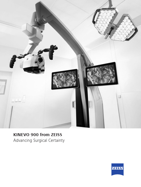
Advancing Surgical CertaintyKINEVO 900 – The Robotic Visualization System Just like you, we love challenging the status quo.The result? Over 100 innovations to perfect the already acclaimed surgical visualization platform. KINEVO® 900 from ZEISS is designedto deliver more functionalities than any surgical microscope today.ZEISS KINEVO 900 combines digital and optical visualization modalities, offers a unique Micro-Inspection Tool and will impress you with its Surgeon-Controlled Robotics. All to enable you to gain greater certainty in a virtually disruption-free workflow.Designed to meet real needs. To make a real difference!A lot more. And, a lot less too.When treating complex vascular conditions, you typically work at high magnification. Even the slightest vibrations can cause disruptions. And constant manual repositioning to better visualize structures or precisely approach deep-seated lesions can become extremely tedious. Not anymore! ZEISS KINEVO 900 delivers a lot more positioning precision with a lot less effort.PointLockSurgeon-Controlled Robotics adds a complete new level of ease to precise positioning. Imagine being able to focus and move around a structure to visualize the targeted anatomy – reducing any manual hassle. In addition, PointLock enables you to do a KeyHole movement to observe a larger area inside a cavity – a particular benefit in areas with narrow access. Simply put:Focus. Activate. Swivel.Active vibration dampingYou know the problems that can be created by the tiniest vibrations. The active damping provided by ZEISS KINEVO 900 minimizes collateral system vibrations, ensuring rock-solid stability. Enabling you to completely, and steadily, focus on what matters most:your treatment.Focus Activate Swivel5When you need it. Where you need it.The new navigation interface of ZEISS KINEVO 900 is designed to work in concert with your navigation device. When you require precise repositioning to reexamine previously visualized structures or when you need to align with a pre-mapped trajectory, making use of all six axes, the Robotic Visualization System ® delivers precise positioning at the push of a button. Putting you exactly where you need to be – when you need to be there.PositionMemoryWhen working on a tumor case, you may already have identified regions of concern where you want to protect the functional structure. After storing these in PositionMemory , you can come back and visualize them at the exact same magnification, working distance and focus – without losing time for manual repositioning. In a nutshell: Save. Move. Recall.Image-guided surgeryMinimize time-consuming efforts in approaching challenging neurosurgicalpathologies. Combine the Surgeon-Controlled Robotics of ZEISS KINEVO 900 with navigation interface to approach deep-seated pathologies in cranial surgery, brain stem or skull base tumor removals –right when you need it.Save Move RecallImage with Brainlab Microscope Navigation Software7New dimensions. Freedom of choice. Working through oculars at extreme angles can sometimes be a pain in the neck. Literally. With no way out, you might have to contend with uncomfortable working positions causing fatigue. Now, relief and revolutionary dimensions in visualization arein sight.The Digital Hybrid Visualization with integrated 4K technology of ZEISS KINEVO 900 welcomes you to a world of heads-up ocular-free surgery, giving you freedom of movement. And freedom of choice to use an optical setup, depending on the application need.Fully integrated 4K camera technologyDuring lateral lumbar or thoracic spine and posterior fossa approaches,ZEISS KINEVO 900’s integrated 4K visualization can be essential. It providesyou with multimodal visualization capabilities – the flexibility to decouple fromthe classic optical approach and to work with outstanding 4K picture qualityand clarity. Even when magnifying tiny details.What’s more… your assistant surgeon, OR staff and residents also benefit from the 4K visual clarity of ZEISS KINEVO 900. They share the same high-resolution, digital image to follow the procedure with comparable fidelity. Delivering indispensable education and training.9Critical challenge. Vital solution.Your challenge: When working from an external perspectiveof a surgical microscope, your visualization of the anatomy is limited to a straight line of sight – missing critical information behind tissue or corners. Efficient and effortless access to this comprehensive information is essential for treatment.Our solution: QEVO® from ZEISSThe unique, proprietary Micro-Inspection Tool from ZEISS complements intraoperative microsurgical visualization, enabling you to discover unexplored areas during the surgical intervention without additional footprint. You can look around corners and eliminate blind spots. And most importantly, you can gain greater insights – for better clinical decisions.To support your surgical workflow, ZEISS QEVO is engineered with an angled design – keeping your hands out of the lineof sight during insertion in the surgical field. And, it allowsfor an easy fit between the ZEISS KINEVO 900 and the situs, eliminating the need to reposition the head of the device. Greater insights, on demand.ZEISS QEVO enables you to inspect the perforator or examine the distal neck of the aneurysm to ensure the clip blades are fully extended.11Ease of use. Peace of mind.Surgical certainty is your imperative. Enabling you to achieve it is ours. That’s why, in the development of the Micro-Inspection Tool, we placed a high priority on its ease of use.ZEISS QEVO is truly integrated. You don’t have to plan foran additional device during surgery. Just plug it into your ZEISS KINEVO 900 for a seamless surgical workflow and to easily switch back and forth between views.ZEISS QEVO is fully autoclavable.So there’s no need forany additional draping. This is another attribute that makes ZEISS QEVO an indispensable tool – always available during surgery. On demand.ZEISS QEVO. Innovation in action.ZEISS KINEVO 900 can support discerning regions that are not directly visualized – avoiding unnecessary bone removal and retraction. During a Vestibular Schwannoma case, for instance, it can help identify the course of facial nerves. And, can support inspection of regions that are not directly visualized by a surgical microscope.1314For the fluorescence distribution: The IntensityMap enables you to conveniently identify relativefluorescence levels reached during the INFRARED800 observation period.For the speed of the flow: The Speed Mapindicates how fast the fluorescence intensityincreased during the observation period –indicating the speed of the blood flow.For the indicative time: The Delay Map (orSummary Map) provides quick information aboutthe time when the fluorescent signal appeared foreach image point in the map.1PZEISS BLUE 4001ZEISS YELLOW 5601Visualization of fluorescence-stained structures using BLUE 400 during surgery.Visualization of fluorescence-stained structures using YELLOW 560.For a complete picture: The Diagram Functionoutlines assessment of fluorescence intensityvariation over time and fast access to the keyindicators for further analysis.BeforeFor no compromises:After15Setting new benchmarks. Shaping a new future. When we envisioned the all-new Robotic Visualization System,we conceived a design that can deliver so much more withoutlosing its familiarity. With ZEISS KINEVO 900, we continue tolive our vision of supporting you in becoming one with yourvisualization system – of delivering purposeful innovations.ones that matter the most for you.The Robotic Visualization System: The first of its kind.Surgeon-Controlled RoboticsDelivering precise positioning with a lotless effort – with motors in all axes.ZEISS QEVO – The Micro-Inspection ToolComplementing intraoperative microsurgicalvisualization to discover unexplored areasduring surgical intervention. Gain greaterinsight. On demand.16Digital Hybrid VisualizationProviding an opportunity for ocular-free surgery, with the freedom to use a traditional optical setup – depending on the application need.Integrated Intraoperative Fluorescence –The Power of Four.The redesigned intraoperative fluorescence technologies from ZEISS offer you the Power of Four – so you always have the tools you need.17Digital connectivity. Transforming OR’s.ZEISS ConnectZEISS Observe Neurosurgery, in particular, is a technologically intensivesurgical discipline. This has pushed us toward the edge oftransformation: to develop leading digital technologiesenabling you to expand the boundaries of surgical care –to the next level.ZEISS KINEVO 900 offers full digital connectivity.Manage surgical data wherever you are: ZEISS Connect App1enables you to access your surgical data from your iOS device,and also delivers dedicated functionalities for efficient work-flows.Take teaching to new heights: ZEISS Observe App enablesyou to virtually broadcast your procedure in the OR. Yourstudents can follow the live surgery directly on mobile screensor immerse themselves in a rich VR Experience.Gain value with new digital services: ZEISS Smart Servicesenables faster support for you and your team with remoteconnectivity. Benefit from the increased system availabilitypowered by a secure connection to your ZEISS KINEVO 900.1 Available soon18Connecting simplicity and innovation.ZEISS SMARTDRAPEYour visualization needs are paramount to us. And, soare the needs of your team. That’s why we gave a specialfocus to the OR preparation process in the developmentof ZEISS KINEVO 900.Being an integral part of the optical path, the SMARTDRAPEwith VisionGuard® from ZEISS is designed together withZEISS KINEVO 900 so you and your team can have thebenefits of a vivid view, and effective patient protection.At the same time – the new innovations make the drapingprocess simply simple!• Innovative folding: to eliminate guesswork and complexity.• Intuitive attachment: for an effortless and simple self-locking mechanism.• Integrated RFID chip: for easy activation of AutoDrape®.Designed for ZEISS KINEVO 900.Support whenever you need it.ZEISS OPTIMEIf you rely on high system availability, consider our ZEISSOPTIME service agreements, which are designed to ensurethe readiness of our medical equipment when you need it.ZEISS OPTIME service agreements for ZEISS KINEVO 900now come with connectivity for ZEISS Smart Services.19Technical DataKINEVO ® 900 from ZEISS5°A x i s 6-25° / +135°A x i s 4±45°A x i s 5-28° / +20°A x i s 3n x 360°A x i s 1M o n i t o r R o t a t i o n : ±125°T i l t i n g : -20° / +5° (±3°)c a . 530 - 1635 m m820 m mm a x . c a .1760m m Technical DataRated Voltage 100 V – 240 VCurrent Consumption Max. 1.350 VARated Frequency 50 Hz – 60 HzElectrical Standard Complying with IEC 60601 1:2005+A1:2012Protection class I, degree of protection IP20Class 2 laser product as perapprox. 525 kg20QEVO® from ZEISS and QEVO ECUTechnical DataDirection of View45° upwardsShaft Diameter 3.6 mmShaft Length120.0 ± 1.0 mmTotal Diameter13.0 mmField of View 100° ± 5° wide angle viewIllumination20 – 35 lumen LEDWeight (without cable)250 gSterilization AutoclavableImage Resolution1920 x 1080 pixel full HDLength of Cable5000 mmOperation Temperature+10 to +40 °C (500/1000 s intermittent use)QEVO ECUDimensions Length = 265.0 ± 1 mm, height = 59.3 ±1 mm and depth = 212.2 ± 1 mmWeight 2.5 kgOperating Voltage24V (+/- 10%) ADCVideo Output DVI-D full HDCable length: 5 m21Technical DataVideoStereo video camera 3D HD, fully integrated, 2 x 3-chip HD, 1080p incl. 2nd HD 3D monitor 4K video camera, fully integrated 3-chip 4K, 2160p Stereo video camera 4K 3D, fully integrated, 2 x 3-chip 4K, 2160p, incl. 2nd HD 3D monitor Integrated HD video recording, withSmartRecording, low-Resolution recording, editing and streaming 2nd system monitor HD 2DAttachment for consumer (SLR) photo camera External 55" 4K 3D video monitor, with mobile cartIntraoperative FluorescenceBLUE 400INFRARED 800INFRARED 800 Compact INFRARED 800 with FLOW 800YELLOW 560Connectivity / Data Manage- mentDICOM module for image and video data transfer from / to PACS. Patient management by modality worklist management.Shared Network Data storage WLAN option, with WiFi Hotspot Navigation Interface Standard Navigation Interface ExtendedAccessories ZEISS QEVO and QEVO ECU12.5x magnetic wide field eyepieces with integrated eyecups Stereo co-observation tubeFoldable Tube f170 / f260, including the PROMAG function for additional 50 % magnification and integrated rotate functionTiltable binocular tube, swivel range 180°, focal length f = 170 mm14-function, wired foot control panel 14-function, wireless foot control panel 2-function foot switch Mouth switch3-step magnification changerApochromatic Optics Motorized focus; Varioskop ® with working distance 200 – 625 mmMotorized zoom; zoom ratio 1:6, magnification factor y = 0.4x – 2.4x10x magnetic wide field eyepieces with integrated eyecupsAutoFokus with 2 visible laser dots, automatic mode with magnetic brakesIllumination 2 x 300 W Xenon, with automatic lamp exchange Automatic Iris Control for adjusting the illumination to the field of view Individual light threshold settingFocus Light Link: working distance controlled light intensityManual adjustment of diameter of field of illuminationAdditional illumination beam to brighten up shadows, motorizedSystem OperationMultifunctional programmable handgrips Magnetic clutches for all system axes Central user interface with full-screen video XY robotic movement in 6 axes (variable speed)Active dampingManual and motorized PointLock function with variable speed PositionMemoryMotorized XY lateral movement with variable speedMultiVision System (HD), with shutter controlSystem Setup AutoBalanceAutoDrape – air evacuation system 1Park Position Drape PositionVideo Integrated 3-chip Full HD video camera, 1080p 24" HD video touchscreen on extendable arm, 16:9 aspect ratioIntegrated still image capturing both on HDD and USB-mediaConnectivity / Data Manage- ment Video-in for external HD video sources Remote diagnosis via internet / VPN Sterile DrapeZEISS SMARTDRAPE1Available with ZEISS SMARTDRAPE only.22Your needs. Our packages.Select a ZEISS KINEVO 900 built to fit your typical clinical use-cases. ZEISS KINEVO 900 comes with pre-defined packages giving you a head start in planning the most suitable configuration for your specific needs.Interested in digital visualization? Check out the digital package. That’s our commitment to cover you for tomorrow while keeping your present needs into focus.always included always included as INFRARED 800 only optional23S U R . 8733 R e v E P r i n t e d i n t h e U n i t e d S t a t e s . C Z -I V /2019 U n i t e d S t a t e s E d i t i o n . O n l y f o r s a l e i n s e l e c t e d c o u n t r i e s .T h e c o n t e n t s o f t h e b r o c h u r e m a y d i f f e r f r o m t h e c u r r e n t s t a t u s o f a p p r o v a l o f t h e p r o d u c t o r s e r v i c e o f f e r i n g i n y o u r c o u n t r y . P l e a s e c o n t a c t o u r r e g i o n a l r e p r e s e n t a t i v e s f o r m o r e i n f o r m a t i o n . S u b j e c t t o c h a n g e s i n d e s i g n a n d s c o p e o f d e l i v e r y a n d d u e t o o n g o i n g t e c h n i c a l d e v e l o p m e n t . R o b o t i c V i s u a l i z a t i o n S y s t e m , K I N E V O , Q E V O , F L O W , A u t o D r a p e , V a r i o s k o p a n d V i s i o n G u a r d a r e e i t h e r t r a d e m a r k s o r r e g i s t e r e d t r a d e m a r k s o f C a r l Z e i s s M e d i t e c A G .© C a r l Z e i s s M e d i t e c A G , 2019. A l l r i g h t s r e s e r v e d .View of the cerebellar tonsils and medulla. Image courtesy of Dr. Robert F. Spetzler, Barrow Neurological Institute, Phoenix, Arizona, USA. (Cover page)View onto cerebellum and lower cranial nerves. Image courtesy of Dr. Robert F. Spetzler, Barrow Neurological Institute, Phoenix, Arizona, USA. (Page 2) Front temporal area for STA-MCA bypass procedure. Image courtesy of Dr. Peter Nakaji, Barrow Neurological Institute, Phoenix, Arizona, USA (Page 2)View onto optic nerve and internal carotid artery. Image courtesy of Dr. Peter Nakaji, Barrow Neurological Institute, Phoenix, Arizona, USA (Page 4)Image-guided surgery. Image courtesy of BrainLab AG (Page 6 and 7)View onto spinal cord dura. Image courtesy of Dr. Robert F. Spetzler, Barrow Neurological Institute, Phoenix, Arizona, USA (Page 8 and 9)Small view of the cerebellum through the Retrosigmoid Approach. Image courtesy of Dr. Peter Nakaji, Barrow Neurological Institute, Phoenix, Arizona, USA (Page 10)Left mini-pterional approach for clipping an aneurysm. Image courtesy of Dr. Peter Nakaji, Barrow Neurological Institute, Phoenix, Arizona, USA (page 11)View onto corpus callosum and septum pellucidum. Image courtesy of Dr. Peter Nakaji, Barrow Neurological Institute, Phoenix, Arizona, USA (Page 12)Transnasal transspenoidal for re-exploration and excision of recurrent pituitary Macroadenoma with possible abdominal fat. Image courtesy of Dr. William White, Barrow Neurological Institute, Phoenix, Arizona, USA (Page 13)Right temporal Craniotomy for AVM. Image courtesy of Dr. Robert F. Spetzler, Barrow Neurological Institute, Phoenix, Arizona, USA (Page 14 and 15)Glioma surgery using BLUE 400. Image courtesy of Prof. Dr. Walter Stummer, University Clinic, Münster, Germany (Page 15)Left-temporal craniotomy for tumor resection with YELLOW 560. Image Courtesy of Dr. Peter Nakaji, Barrow Neurological Institute, Phoenix, Arizona, USA. (Page 15)Carl Zeiss Meditec AG Goeschwitzer Strasse 51–52 07745 Jena Germany/med /kinevoCarl Zeiss Meditec, Inc.5160 Hacienda Drive Dublin, CA 94568USA/med/us。
压力变送器英文参数定义

压力变送器英文参数定义Pressure transmitters are devices that convert pressure into a standard electrical signal output, typically used in industrial automation and process control systems. They are essential components in a wide range of applications, including fluid systems, pneumatic systems, and hydraulic systems, where precise measurement and control of pressure are crucial.The fundamental components of a pressure transmitter include a pressure sensor, a signal conditioning circuit, and an output interface. The pressure sensor, typically a piezoelectric or piezoresistive device, measures the pressure applied to it and converts it into an electrical signal. The signal conditioning circuit processes this signal, amplifying it and converting it into a standard output signal such as 4-20mA or 0-10V. The output interface then transmits this signal to the control system forfurther processing.The key parameters of a pressure transmitter are its measurement range, accuracy, stability, and response time. The measurement range refers to the minimum and maximum pressures that the transmitter can measure. Accuracy is a measure of how closely the transmitter's output matches the actual pressure being measured, typically expressed as a percentage of the full scale range. Stability refers to the transmitter's ability to maintain its accuracy over time and under varying environmental conditions. Response timeis a measure of how quickly the transmitter can respond to changes in pressure.Other important parameters include the power requirements of the transmitter, its operating temperature range, and its compatibility with different media and environments. For example, some transmitters are designed for use in explosive atmospheres or with corrosive fluids, while others are suitable for use in high-temperature or high-pressure environments.In terms of electrical specifications, pressure transmitters typically have an analog output signal, suchas 4-20mA or 0-10V, which is compatible with mostindustrial automation systems. They may also have digital communication interfaces such as HART, Profibus, or Modbus, which allow for more advanced monitoring and control capabilities.Installation and calibration of pressure transmitters are crucial to ensure accurate and reliable performance. The transmitter should be mounted in a location that allows for proper sensing of the pressure being measured, while also considering factors such as temperature, humidity, and vibration. Calibration is typically performed at regular intervals to compensate for any drift in performance over time.In conclusion, pressure transmitters play a vital role in industrial automation and process control systems, enabling precise measurement and control of pressure in a wide range of applications. Understanding the key parameters and specifications of these devices is essential for selecting the appropriate transmitter for a given application and ensuring optimal performance.。
可控硅相位控制原理

可控硅相位控制原理English:The principle of phase control in a thyristor, also known as a silicon-controlled rectifier (SCR), involves controlling the firing angle of the thyristor to regulate the power delivered to a load. The thyristor is a four-layer, three-junction semiconductor device that can only conduct current when triggered into its conducting state. The control of the firing angle is achieved through the application of a gate pulse at the gate terminal of the SCR.When an AC voltage is applied to the input terminals of the thyristor circuit, initially the thyristor blocks the current flow as it is in its non-conducting state. In order to trigger the thyristor into conduction, a gate pulse is applied at the gate terminal. The gate pulse is generally a short-duration, low-voltage signal synchronized to the AC waveform. When the gate pulse is applied within a particular time window, which corresponds to the desired firing angle, the thyristor gets triggered into conduction, allowing the load current to flow.By controlling the phase angle at which the gate pulse is applied, the firing angle of the thyristor can be adjusted. This determines the point in the AC waveform at which the thyristor starts conducting. As the firing angle is reduced, the thyristor conducts for a longer duration during each half-cycle of the AC waveform, resulting in increased power delivery to the load. Conversely, increasing the firing angle reduces the conduction duration and decreases the power delivered to the load.The controlled firing angle allows for efficient power control in applications like motor speed control, light dimming, and power factor correction. Additionally, phase control helps in the reduction of harmonic distortions and minimizes the generation of electromagnetic interference. With the appropriate gate pulse triggering, the thyristor can be turned on and off at specific points in the AC waveform, enabling precise control over power delivery.中文翻译:可控硅的相位控制原理,也称为硅控整流器(SCR),涉及通过控制可控硅的触发角以调节传送给负载的功率。
- 1、下载文档前请自行甄别文档内容的完整性,平台不提供额外的编辑、内容补充、找答案等附加服务。
- 2、"仅部分预览"的文档,不可在线预览部分如存在完整性等问题,可反馈申请退款(可完整预览的文档不适用该条件!)。
- 3、如文档侵犯您的权益,请联系客服反馈,我们会尽快为您处理(人工客服工作时间:9:00-18:30)。
A controller enabling precise positioning and sway reduction in bridge andgantry cranesKhalid L. Sorensen, William Singhose, Stephen DickersonThe George W. Woodruff School of Mechanical Engineering, Georgia Institute of Technology, 813 Ferst Dr., MARC 257, Atlanta, GA 30332-0405, USAReceived 28 September 2005; accepted 30 March 2006Available online 5 June 2006AbstractPrecise manipulation of payloads is difficult with cranes. Oscillation can be induced into the lightly damped system by motion of the bridge or trolley, or from environmental disturbances. To address both sources of oscillation, a combined feedback and input shaping controller is developed. The controller is comprised of three distinct modules. A feedback module detects and compensates for positioning error; a second feedback module detects and rejects disturbances; input shaping is used in a third module to mitigate motioninduced oscillation. An accurate model of vector drive and AC induction motors, typical to large cranes, was used jointly with a deconvolution analysis technique to incorporate the nonlinear dynamics of crane actuators into the control design. The controller is implemented on a 10-ton bridge crane at the Georgia Institute of Technology. The controller achieves good positioning accuracy and significant sway reduction. r 2006 Elsevier Ltd. All rights reserved.Keywords: Input shaping; Command shaping; Crane control; Oscillation control; Anti-sway; Bridge crane; Gantry crane1. IntroductionBridge and gantry cranes occupy a crucial role within industry. They are used throughout the world in thousands of shipping yards, construction sites, steel mills, warehouses, nuclear power and waste storage facilities, and other industrial complexes. The timeliness and effectiveness of this manipulation system are important contributors to industrial productivity. For this reason, improving the operational effectiveness of cranes can be extremely valuable.These structures, like the one shown in Fig. 1, are highly flexible in nature. External disturbances, such as wind or motion of the overhead support unit (e.g. the bridge or trolley), can cause the payload to oscillate. In many applications these oscillations have adverse consequences. Swinging of the payload or hook makes precision positioning time consuming and inefficient for a human operator; furthermore, when the payload or surroundingCorresponding author. Fax: +14048949342.E-mail address: Singhose@ (W. Singhose).0967-0661/$-see front matter r 2006 Elsevier Ltd. All rights reserved.doi:10.1016 /j.conengprac. 2006.03.005obstacles are of a hazardous or fragile nature, the oscillations may present a safety risk (Khalid, Singhose, Huey, & Lawrence, 2004).The broad usage of bridge and gantry cranes, coupled with the need to control unwanted oscillations, has motivated a large amount of research pertaining to the control of these structures. Engineers have sought to improve the ease-of-use, increase operational efficiency, and mitigate safety concerns by addressing three primary aspects of crane systems: (1) motion-induced oscillation; (2) disturbance-induced oscillation; and (3) positioning capability.Singer et al. reduced motion-induced oscillations of a 15-ton bridge crane by using robust input shaping techniques (Singer, Singhose, & Kriikku, 1997). Fang et al. proposed to control final trolley position and motioninduced oscillation through proportional-derivative ( PD ) control in which the coupling between the cable angle and the motion of the trolley was artificially increased (Fang, Dixon, Dawson, & Zergeroglu, 2001). Piazzi proposed adynamic-inversion-based control for reducing transient and residual motion-induced oscillation (Piazzi & Visioli,Fig. 1. Picture of a gantry crane at a shipping dock (courtesy of Favelle Favco Cranes).826 K.L. Sorensen et al. / Control Engineering Practice 15 (2007) 825–8372002). Kim implemented a pole-placement strategy on a real container crane to control motion and disturbanceinduced oscillation, as well as final positioning (Kim, Hong, & Sul, 2004). Moustafa developed nonlinear control laws for payload trajectory tracking based on a Lyapunov stability analysis (Moustafa, 2001). O’Connor developed a control strategy based on mechanical wave concepts that involves learning unknown dynamics through an initial trolley motion (O’Connor, 2003). Finally, Fliess used a generalized state variable model suggested in (Fliess, 1989), and then proposed a linearizing feedback control law (Fliess, Levine, & Rouchon, 1991). The position of the trolley and length of the payload cable were the controlled variables, and their respective reference trajectories were limited to a class of fourthorder polynomials to insure minimal payload sway. The control did not attempt to eliminate disturbance-induced oscillations.The control schemes developed in the literature may be broadly grouped into three categories: time-optimal control, command shaping, and feedback control. The implementation of these various control methods presents several challenges. A common difficulty is the behavior of drives and motors that actuate crane motion. Nonlinear behavior of these elements have been difficult to evaluate with traditional analysis techniques, and are, therefore, often neglected in controller designs.A drawback related to time-optimal control is its inability to be implemented in real-time, owing to the necessity of precomputation of system trajectories. There is no known implementation of a time-optimal control scheme used with a commercial crane (Gustafsson & Heidenback, 2002). Command shaping is a reference signal modification technique that is implementable in real time (Singer & Seering, 1990). However, command shaping does not have the closed-loop mechanisms of feedback control, and must, therefore, be used in conjunction with a feedback control if it is to be used for disturbance rejection.Feedback control is the most common strategy used in research efforts to mitigate positioning and cable sway errors. This type of control is aptly suited for positioning a bridge or trolley. However, when a feedback controller must minimize cable sway, the control task becomes much more problematic. Accurate sensing of the payload must be implemented, whichis often costly or difficult. These difficulties are discussed in detail for fully automatic commercial cranes in use at the Pasir Panjang terminal in Singapore (Gustafsson & Heidenback, 2002). Furthermore, feedback control schemes are somewhat slow because they are inherently reactive. For example, when feedback is utilized to control cable sway, cable sway must be present in the system before the control will attempt to eliminate the undesired oscillations.One of the most useful techniques used for negating a system’s flexible modes is input shaping. Input shaping does not require the feedback mechanisms of closed-loop controllers. Instead, the control reduces oscillations in an anticipatory manner, as opposed to the reactive manner of feedback. Oscillation suppression is accomplished with a reference signal that anticipates the error before it occurs, rather than with a correcting signal that attempts to restore deviations back to a reference signal. In the context of crane control, this means that sensing cable sway is not necessary. As a result, input shaping is easier to implement than feedback schemes. In many instances, input shaping techniques are also amenable to hard nonlinearities present in actuating drives and motors. Input shaping techniques have proven effective at significantly reducing motioninduced cable sway during crane motion (Kenison & Singhose, 1999; Lewis, Parker, Driessen,& Robinett, 1998; Singer et al., 1997; Singhose, Porter, Kenison, & Kriikku, 2000). Cranes utilizing the input shaping control also exhibited a significant improvement in efficiency and safety (Khalid et al., 2004).The controller developed in this paper has been designed with positioning and oscillation suppression properties by merging feedback control with input shaping. The control is comprised of distinct modules that have been combined into a unified control architecture. Each module is designed to control one aspect of the crane’s performance. A feedback control module is used to position the payload at a desired location, while a different feedback module rejects disturbances. Input shaping is used in a third module to minimize motion-induced oscillation.This strategy of allocating individual control tasks to individual controllers is similar to the approach used by Sorensen, Singhose, and Dickerson (2005). The strategy helps mitigate design and implementation difficulties discussed previously by utilizing the strengths of the different control modules for tasks they are most suited for, feedback for positioning and disturbance rejection, and input shaping for reducing motion-induced oscillation in the presence of hard nonlinearities. The performance of the control is evaluated experimentally on a 10-ton bridge crane located in the Manufacturing Research Center (MARC) at the Georgia Institute of Technology ( Georgia Tech).The following section provides a synopsis of crane system dynamics that incorporates the effects of nonlinear drives and motors. Section 3 presents a brief overview of the overall control system followed by a more detailed description of the individual modules comprising the controller. The stability of the two closed-loop modules is also discussed. Section 4 explains how the distinct modules are combined into a single control architecture, and examines the stability of the combined architecture. Section 5 contains concluding remarks. Experimental data are used throughout the paper to demonstrate key aspects of the control system.2. Crane dynamicsThe 10-ton MARC crane used to test the control described here is shown in Fig. 2. Planer motion of this crane can be simply modeled as a pendulum suspended from a moving support unit, as shown in Fig. 3. The mass of the overhead support unit and mass of the payload are labeled as m t and m p, respectively; acceleration due to gravity is represented as g; a viscous damping force, which acts on the payload, can beK.L. Sorensen et al. / Control Engineering Practice 15 (2007) 825–837 827described by the damping coefficient b; and the length of the suspension cable is labeled as L. The trolley position, x, willbe considered as the controlled variable. An obvious benefit to such a choice for the system input is that a model of crane motors and industrial drives is unnecessary at this juncture. Later these systems will be considered when determining the responseFig. 3. Multi-body model of the crane along one axis.of the system to reference signals. A similar modelingformulation was used in Fliess et al. (1991).With the crane modeled in this manner, the system is reduced to one degree of freedom with the cable angle, y, used as the independent coordinate.The differential equation of motion is y € þ b y _ þ gsin y ¼ cos y x €. (1)Lm p L LThe limited cable sway of crane systems allows one to assume a small angle approximation, reducing (1) to:y € þ b y _ þ g y ¼ 1x €. (2)Lm p L LRecognizing that (2) represents a second-order damped oscillatory system, one may write bLm p¼ 2zo n ,(3)V rpFig. 4. Input velocity–output angle relationship for a crane.Fig. 5. Model of AC induction motors and vector drives.transfer function expressed in (6). The velocity of the overhead support unit, V t , causes the payload plant to respond with cable angle y p . Also illustrated in Fig. 4 is the relationship between the support unit velocity, V t , and the desired reference velocity, V r . The actual velocity of the support unit is the response of the plant labeled ‘‘Drive & Motors’’ to the reference velocity. This plant is a composite representation of the actuation elements and craneFig. 2. Bridge crane in the Manufacturing Research Center. Fig. 4, where the block labeled as ‘‘Payload’’ represents theg L¼ o 2 n (4), and 1 L ¼ o 2 n g. (5)the a system obtain r epresentation r elating To velocity o f may the o verhead s upport u nit t o the a ngle o f t he c able o ne of t he s upport position, unit the derivative time substitute _ v t, for € x . Assuming zero initial conditions, and using the relations in (3) through (5) , one obtains the following transfer f unction r elating t he c able a ngle t o t he velocity o f support unit:the Y ð s Þ V t ð s Þ ¼ ð o 2 n = g Þ s s 2 þ 2 z o n s þ o 2 n . (6) This relationship is represented as a block diagram inyxm tDatumm pInput, xm p gθ bLθDrive &MotorsV tPayloadV tV rY NPRate LimiterSwitch V r 0H828 K.L. Sorensen et al. / Control Engineering Practice 15 (2007) 825–837mass. These elements are comprised of the bridge and trolley masses, motors, and drives.An accurate model of industrial AC induction motors, vector drives, and support unit mass, typical for large cranes, was derived in Sorensen (2005). This model is represented in the block diagram of Fig. 5.The model relates the velocity response of drives and motors to a desired reference velocity. Three elements comprise the model: a switch, a rate limiter, and a linear, second-order, heavily damped plant, H. The switching element ordinarily passes the original reference signal, V r , to the rate-limiting block. However, when transitional velocity commands are issued to the crane, the switch temporarily sends a signal of zero. Transitional velocity commands are those commands that change the direction of travel of the crane (forward to reverse or vise versa). This type of behavior depends on V r and V t , and can be described with the following switching rules:8 >< V r ; SignðV r Þ ¼ SignðV t Þ;Switch output ¼ V r ; jV t jp X%; (7)> : 0;otherwise :This model may be used to represent the response of many industrial vector drive and AC induction motor combinations by proper selection of four parameters associated with the model: the slew rate parameter of the rate limiter, S; the switch percent of the switch element, X%; the natural frequency of H; and the damping ratio of H. For the MARC crane, these parameters were estimated to be 160%/s, 0.9%, 6.98rad/s, and 0.86, respectively.Time (s)Fig. 6. Comparison of actual and simulated responses to several velocity commands.The response of the model closely follows the actual response of the MARC crane. This can be seen in Fig. 6, where the response of the model and the response of the actual support unit to several velocity commands have been overlaid.3. Combined input shaping and feedback controlThe crane described in Section 2 is comprised of a linear payload plant and a nonlinear drive/motors plant. The control system described here generates reference velocity commands that, when issued to the nonlinear drive and motors, achieve three desirable results in the payload: (1) precise positioning; (2) motion-induced oscillation suppression; and (3) disturbance rejection. A block diagram of the overall control system is shown in Fig. 7.The means by which the combined control accomplishes the three objectives is easily understood by separately considering the individual modules comprising the controller. The following subsections provide a description of each of the three modules. The stability of the closed-loop modules is also discussed.3.1. Input shaping moduleA successful approach to suppressing oscillation in linear plants is to generate a reference command that drives a system to cancel out its own oscillation. One such technique, input shaping, is implemented by convolving a sequence of impulses, known as an input shaper, with a reference signal (this process is illustrated in Fig. 8). The shaped command is then used to drive the linear system.The amplitudes and time locations of the impulses comprising the input shaper are determined by solving a set of constraint equations that attempt to limit the unwanted system dynamics. All that is needed to solve the equations is an estimate of the system natural frequency and damping123 -100-5050100Actual Response Simulated ResponseResponse 1Response 1Response 1ARTICLE IN PRESSK.L. Sorensen et al. / Control Engineering Practice 15 (2007) 825–837 829Original ZV Shaped Command Shaper Command H 0 0 Δ 0 Δ Fig. 8. The input shaping process.V r pFig. 9. Input shaping module.Fig. 10. Nonlinear and equivalent linear block diagrams: (a) generalized inputshaping module and (b) equivalent input shaping module.ratio. If the amount of residual oscillation produced by the sequence of impulses is set equal to zero, then a shaper satisfying the constraint equations is called a Zero Vibration (ZV) shaper (Singer & Seering, 1990; Smith, 1957). The ZV shaper shown in Fig. 8 has two impulses that change the original step command into a staircase shaped command. The rise time of the modified command is increased by the duration of the shaper, D.Implementing input shaping on a physical system, such as the MARC crane, is accomplished in the manner shown in Fig. 9. The shaped commands are first sent to the drive and motors, then the response of the drive and motors actuate the payload. Given this configuration, one must determine what influence the nonlinear drive and motors have on the ability of the shaped commands to eliminate oscillations from the payload. If the drive and motors can be represented as a linear transfer function, then there is no detrimental effect on the oscillation suppression of the input shaper; this is due to the commutability of the input shaper and linear plant. However, the model contains a nonlinear rate limiter, as well as anonlinear switch; therefore the possibility of representation by a transfer function is precluded.To understand the effects of the nonlinear drive and motorsplant, consider the block diagram of a system shown in Fig. 10awhere an arbitrary reference signal, X, is modified by input shaper A to produce a shaped command, X s . Assume that thereference signal eventually obtains a steady-state value. Alsoassume that the input shaper is designed to cancel the oscillations of a linear plant, G. If X s is used as an input to a nonlinear plant,such as the drive and motors model, then the response of the nonlinear plant may be represented as Y NP .The same nonlinear response, Y NP , could be obtained by an alternate process where some baseline command, W, is modified by input shaper B (not necessarily consisting of an impulse sequence suitable for eliminating oscillations in G) , reducing thesystem to that of Fig. 10b . This is an equivalent system that contains no nonlinear elements. Fig. 11 demonstrates this processwhen X is a step input, and the nonlinear plant consists of a rate limiter with slew rate parameter, S. Notice that an identicalresponse, Y NP , is generated by command W and ZV shaper B. The process of resolving an arbitrary signal into a baseline command and an input shaper is called deconvolving. If it can be shown that the input shaper resulting from the deconvolution (shaper B) consists of an impulse sequence suitable for eliminating oscillations in G, and that the baseline command, W, obtains some steady-state value, then the nonlinear elements ofthe original system will have no detrimental effects on the oscillation suppression properties of the shaped signal, X s . This is because the original system behaves as if the signal Y NP was created by properly shaping a command for G. If both of theseFig. 7. Combined input shaping, positioning, and disturbance rejection controller.P r+- P bV b PDControlInputShaperea dm Payload PDControlDrive & Motors Payload( Model )Drive & Motors ( Model )P EV sV c+ + + V r+ + Positioning BlockDisturbance Rejection BlockShaping Block* Time HTime Input Shaper Payload V s V bDrive & Motors Input Shaper A Nonlinear Plant X X s Y N P G Y G Input Shaper BW Y N P G Y G ( a )( b )ARTICLE IN PRESS830 K.L. Sorensen et al. / Control Engineering Practice 15 (2007) 825–837Table 1 Acceptable slew rates for a rate limiter following an input shaping moduleconditions cannot be met, then the nonlinear elements ofNatural Frequency, ωHFig. 12. Effects of the switching element on residual oscillation amplitude.the original system can diminish the oscillation reducing properties of the original input shaper.To evaluate the detrimental effects of a rate limiter on a shaped command for any command X, and any slew rate parameter, S, one may perform an exhaustive deconvolution analysis for every combination of X and S. Of course this is not practical. Instead, one may quickly evaluate rate limiter effects through the use of a non-dimensional ratio R ZV . This ratio relates how rapidly a rate limiter alters a reference signal to how rapidly a ZV input shaper alters a reference signal. It is defined as R ZV ¼ ðD ZV =50%ÞS, where D ZV is the shaper duration. A rate limiting element has no detrimental effect on a ZV input shaper, regardless of the command X or parameter S, for the following range ofR ZV : 1p R ZV p N, or R ZV ¼ 1=n, n ¼ 1, 2, 3,y. The R ZV value for the MARC crane is well within acceptable limits. These results are summarized in Table 1.The deconvolution analysis technique was also used to analyze the effects of the switching element on the ZV shaper (recall that the switching element affects motor response only when transitional velocity commands are issued to the crane). It was found that detrimental effects do exist, and that the severity of these effects varies approximately as the inverse of the natural frequency of H. Even so, given the value of H for the MARC crane, the induced oscillation caused by the switch element is still significantly lower than if shaping were not used. This is clearly demonstrated in Fig. 12. The solid line in this figure was obtained through simulations; it shows how the residual oscillation amplitude when input shaping is used varies with o H , the natural frequency of H. The triangle and square markers are the experimental oscillation amplitudes with and without shaping, respectively; their placement on the graph corresponds to the value of o H for the MARC crane.In light of the foregoing results, one is assured that the input shaping module of Fig. 9 significantly reduces motion-induced oscillations in the payload, even in the presence of nonlinearities of the drive and motors plant.The beneficial effects of input shaping were verified by having numerous operators drive the crane through a cluttered work environment both with and without input shaping (Khalid et al., 2004). While the crane was in motion, a downward looking video recorder captured the payload motion. Fig. 13 compares the responses from a typical trial. During unshaped motion the hook oscillated when the crane was commanded to move and after it was commanded to stop, in addition, the payload collided twiceFig. 13. Shaped and unshaped payload motion in a cluttered work environment.GGFig. 11. Generating Y NP from W and shaper B.Rate Limiter YN P X s ZV Shaper AXY N P W ZV Shaper B5 10 15 20 2530 35 400 12 3 4 5 6 78 Residual oscillation amplitude ofMARC crane for unshaped transitional velocity commandResidual oscillation amplitude of MARC crane for shaped transitional velocity commandK.L. Sorensen et al. / Control Engineering Practice 15 (2007) 825–837831with surrounding obstacles. In contrast, the shaped trajectory shows that the motion-induced oscillations were eliminated and no collisions occurred.3.2. Positioning moduleConsider again the transfer function in (6) that relates the cable angle to the velocity of the overhead support unit. A state space representation of this plant follows directly from the coefficients of the transfer function:A ¼ o 2 2zo n ; b ¼ 1 ; and c ¼ 0 g . (9)nGiven the relationship between q2 and y established in (8), one may recognize that the state q 2 is equal to yL, the relative horizontal displacement between the trolley and the payload.Computing the eigenvalues of A, we havel ¼ zo n o d i.(10)Because the real part of the eigenvalues of A are negative, the state q2 is asymptotically stable in the sense of Lyapunov. Therefore, q2 always approaches zero. By this formal treatment of the state equations, an obvious fact is emphasized: the payload will always come to rest directly beneath the overhead support point. Therefore, precise positioning of the overhead support unit is equivalent to precise positioning of the payload. This fact enables the positioning module to be designed as a collocated controller of the overhead support unit instead of a non-collocated controller of the payload, thus simplifying the control objective significantly. This payload positioning strategy using a PD controller is illustrated in the block diagram of Fig. 14.This module controls the position of the payload along the bridge axis. A desired position is issued to theFig. 14. Positioning control module.controller as a position reference signal, P r. On the MARC crane, a laser range sensor provides feedback of the bridge position, P b. These two signals are compared to generate an error signal, P E, which is sent to the PD block. In response to the error signal, the PD block generates a signal representing a desired bridge velocity. To prevent this signal from over-driving the bridge beyond a safe speed, a saturator has been inserted after the PD control block. The truncated reference velocity, V r, is sent to bridge drive and motors, which causes the bridge to respond with velocity V b. Finally, the payload responds to the bridge velocity with cable angle, y p.The stability of the module may be determined by first considering the outputs, V b and y p. The system is considered to be BIBO stable if for any bounded inputs into the system, the outputs, V b and y p are also bounded. Secondly, because of the presence of hard nonlinearities (e.g. the saturation block, switching element, and rate limiter) one must also be concerned about the existence of limit cycles.The BIBO stability of the system is quickly ascertained by considering the eigenvalues of H (the second-order plant in the drive and motors model), and the payload. For each, the eigenvalues have negative real parts. Therefore, for any bounded input into each of these plants, the outputs V b and y p will also be bounded. The boundedness of V b is immediately apparent because of the saturated boundedness of V r. Given that V b is bounded, y p is also bounded.Predicting the presence of limits cycles in systems with ‘‘hard’’ nonlinearities, like saturation or rate limiting elements, has been performed for many years through the use of methods based on the sinusoidal input describing function. The describing function method is an approximating technique that allows one to predict a range of controller gains for which a system will likely not exhibit limit cycles. Because of the approximate nature of the technique, three kinds of inaccuracies are possible (Slotine & Li, 1991):(1)The amplitude and frequency of the predicted limit cycle arenot accurate.(2)A predicted limit cycle does not actually exist.(3)An existing limit cycle is not predicted.Historically, the describing function method has been used on systems with exactly one nonlinear element. Recently, new studies have been conducted to better understand limit cycles that may exist due to multiple nonlinear elements (Anderson, 1998). For a system withProportional Gain, K pq_ ¼ Aq þ bv tðtÞ;whereyðtÞ ¼ cq;(8)" 01# 0 o2n+ P rP b P E V bPayload PDControlSaturationBlockV rDrive &Motors p。