外文翻译 基于无线传感器网络的智能方法相结合的状态监测和故障诊断
《制造业自动化》2011年总目录

面 投影 微立 体光 刻 系统 的开发 和研 究… …… 一 19 (2 ) 锅 炉温 度 测控 系统 的设计 …… …… …… …… 一 1 3 (3 )
次装夹 实现 管板和法兰 零件 的车铣复合加工 -3 ) - 9 (
设计 与计 算 …… …… …… ……… …… …… 一 4 ) (3
柴油 汽车 发动机 气 门弹 簧的最 优化
C 16 床主轴 刚度研 究 ……… …… ……… (3) K6 3车 18 高速 电主 轴热 态性能 分析… …… ……… …… 一 1 1 (4 )
务I 匐 似
《 制造业 自动化》2 年总 目录 0 1 1
第1 ( 期 上)
基于 集成化 企 业模 型的访 问控 制机制 与 系统 研 究 … …… …… …… ……… …… …… … () 1 云制 造 中的关 键技 术分析 … ……… …… ……… - 7 .) ( 基 于Po B s 的 物流 生产线 网络 监控 rf u . i DP 系统 设 计与 实现 … ……… …… …… …… …“(1 1) 气动 安装机 械手 的P C 制 ……… …… ……… (2 L 控 8) 基于 小世 界网络 模型 的复 杂产 品设 计变 更
大 客车横 向稳 定杆 的虚拟疲 劳分 析… ……… 一 1 5 (4 ) 企 业生产 规划 多 目标决策方 法 的应用研 究… “ 1 8 (4 ) 基 于U 的嵌 入式 系统 可视化 建模研 究 …… ・1 0 ML (5 )
一
输 油管布 置 的数 学模 型… …… …… …… ……… (5 4) 基 于云计 算技 术 的设 备 管理 系统研 究与 开发… (8 4)
一
种 复 杂产 品研发 决策 支持 系统 的结构 与 流程 设 计 ……… …… …… …… …… ……… - 5 ) - 2 (
电力设备的在线监测与故障诊断

在线监测与故障诊断技术的发展趋势和未来发 展方向
智能化:利用人工智能和大数据技术提高监测和诊断的准确性和效率。
实时性:提高监测的实时性,以便及时发现和解决故障,减少设备 停机时间。
远程化:通过远程监测和诊断技术,减少现场维护成本和时间。
集成化:将多个监测系统集成在一起,实现统一管理和数据共享。
提高在线监测与故障诊断技术的有效途径和方 法
添加标题
添加标题
添加标题
数据处理模块:对采集的数据进 行预处理、分析和特征提取,为 后续的故障诊断提供依据。
预警与控制模块:根据故障诊断 结果,及时发出预警信号,并采 取相应的控制措施,保障电力设 备的安全稳定运行。
监测技术应用场景
变压器在线监测
高压断路器在线监测
输电线路在线监测
配电设备在线监测
监测技术发展趋势
提高运行效率:通过对电力设备的在线监测和故障诊断,优化设备运行状 态,提高运行效率。
在线监测与故障诊断技术在电力设备故障预警 和预防中的作用
预测设备寿命,制定维修计 划,避免突然停机
提高设备运行可靠性,减少 非计划停机时间
实时监测设备运行状态,及 时发现潜在故障
为故障诊断提供数据支持, 辅助技术人员快速定位故障
电力设备在线监测与故障诊断的应 用
在线监测与故障诊断在电力系统中的重要性
提高电力设备运行可靠性:通过实时监测和故障诊断,及时发现并解 决潜在问题,降低设备故障率,提高运行稳定性。
延长设备使用寿命:及早发现设备异常,采取相应措施,可有效延 长设备使用寿命,降低更换成本。
提高电力系统的安全性能:在线监测与故障诊断能够及时发现并预警 潜在的安全隐患,保障电力系统的安全稳定运行。
基于ZigBee和GPRS的液压设备远程故障诊断系统
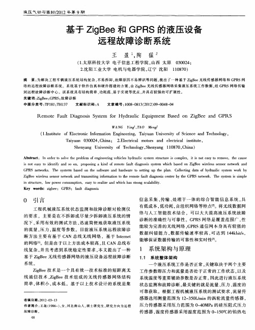
Z g e w rl s e s rn t r n r n mi n n o ma in t h e t a l d a n ssc n e y t e GP ewo k iBe iee s s n o ewo k a d ta s t g if r t o t e r moe fu t i g o i e trb h RS n t r .T e s s m s s l i o h y t i i e e mp
中 图 分 类 号 : P 8 ; H1 7 T 1 1T 3 文 献 标 识 码 : A 文 章编 号 :0 8 0 1 ( 0 2 0 - 0 8 0 10 — 8 3 2 1 )9 04 —4
R e o e Fa l a no i S se m t u t Dig ss y tm f r H y r u i u p e s d n ZiBe a d o d a l Eq i m nt Ba e O g e n GP S c R
有低 成本 , 低功耗 , 自组 织 网络等特 [ 2 1 。将无 线数 据 网
Ab t a t I r e o s l e t e p o lm fe g n e i g v h ce y r ui y tm tu t r s c mpe , i i n te s o r mo e t e c u e sr c : n o d rt o v h r be o n i e r e i ls h d a l s s n c e sr cu e i o lx t s o a y t e v , h a s i n t e s o i e t y a d S n p o o i g a k n f r moe fu t d a n ss s s m h c a e n Z g e r ls e s r n t r n s o a y t d n i n O o , r p sn i d o e t a l i g o i y t f e w ih b s d o iB e wi e s s n o ewo k a d e GP S n t r s T e y tr b s d o h ot a e a d h r wa e t e t g u h l n C l ci g d t f h d a l y t m o k b R ewok . h s s m a e n t e s f r n a d r o s t n p t e p a . ol t aa o y r u i s se w r y e w i e n c
无线传感器网络故障诊断检测技术
无线传感器网络故障诊断检测技术摘要:随着现代社会的发展和研究领域的深入使现代传感器技术、微机电系统、通信技术、嵌入式计算机技术和分布式信息处理技术等成为无线传感器网络的综合性的交叉领域。
在当今社会广泛应用,为了使无线传感器网络的应用质量达到保证,针对无线传感器网络故障的研究是必要的。
本文通过对无线传感器网络的应用、性能指标来研究其故障诊断和技术方法。
关键词:无线传感器网络、故障诊断1绪论1.1无线传感器的结构及特点传感器节点、汇聚节点和管理站等结构组成无线传感器网络。
在监测区域附近存在大量自我组织构成网络的传感器节点。
节点得到的数据经逐个节点传输并且数据被多个节点处理后路由到汇聚节点,最后通过Internet等无线传输方式到达管理站后管理站进行监测和管理。
特点有能量资源有限、硬件资源有限、无中心、自组织、多跳路由、动态拓扑、节点数量多、可靠性等。
1.2无线传感器网络的设计要点无线网络的设计将直接影响其工作的性能和效率所以网络协议起到使各个独立的节点组成可以进行多跳的数据网络而时间同步实现了其自身协议运行、数据融合、协同睡眠及定位的基础;目标定位确定节点位置,硬件平台和嵌入式操作系统也是无线传感器网络的主要因素,通过拓扑控制对自组织的无线传感器网络生成良好的网络结构从而提高路由协议和MAC协议的效率。
2无线传感器网络故障的应用2.1无线传感器网络的应用领域1)军事应用在军事应用中无线传感器网络可以达到实现对敌军行为的实时监控、监测、目标位置锁定、战场的评估、核攻击、核生化武器攻击的监测搜索等任务还可以对周围各种参数进行实时分析和信息进行采集,如温度、湿度、气体、声音、磁场、红外线、震动等。
作战时在友军身上装入传感器节点可起到保护友军的作用,避免误伤,在定位导弹发射点和飞机抛撒等方面也起到重要作用。
低成本的网络且具有容错性有优势,因此,常常被国家的军队所关注。
2)医学、健康监测应用用于医学研究和检测治疗,在医疗系统和健康护理方面应用广泛,可监测人体多种生理指标数据并且对患者和医生的行为进行跟踪定位,医院的药物管理等。
输变电设备在线监测技术分析及应用
输变电设备在线监测技术分析及应用1. 引言1.1 背景介绍传统的定期检修和检测方式存在着时间成本高、周期长、监测不及时等缺点,无法满足快速发展的电力系统对设备安全稳定运行的需求。
引入在线监测技术成为解决这一问题的有效途径。
通过对输变电设备进行在线监测,可以实现对设备的实时监测和预譳故障诊断,及时发现潜在的故障隐患,提高输变电设备的运行安全性和可靠性。
本文将从输变电设备在线监测技术的背景介绍、研究意义和研究目的入手,探讨该技术的概述、主要监测技术、应用案例分析、技术优势与不足以及未来发展趋势,从不同角度全面分析输变电设备在线监测技术的现状和未来发展方向。
1.2 研究意义输变电设备在线监测技术的研究意义主要体现在以下几个方面:1. 提高设备可靠性和安全性。
传统的定期检测往往无法准确及时地发现设备故障,导致设备损坏或发生事故。
而在线监测技术能够实时监测设备运行状态,及时发现问题并采取措施,从而提高设备的可靠性和安全性。
2. 降低维修成本和停机时间。
传统的定期检测需要停机检修,影响了设备的正常运行,同时也增加了维修成本。
而在线监测技术可以实现设备的无停机检修,提高了设备的运行效率,降低了维修成本和停机时间。
3. 实现设备远程监控和管理。
传统的设备监测需要人工操作,工作量大且容易出现疏漏。
而在线监测技术可以实现设备的远程监控和管理,减轻了人力负担,提高了管理效率。
1.3 研究目的本文旨在探讨输变电设备在线监测技术的发展现状和应用情况,分析主要监测技术的优势与不足,并结合实际案例进行深入分析。
通过对不同在线监测技术的比较和评价,探讨其在输变电设备运行中的作用和价值,为相关领域的研究和实践提供参考和借鉴。
本研究旨在总结当前在线监测技术的发展趋势,展望未来在输变电设备领域的应用前景,为进一步完善和提升监测技术的水平提供参考和建议。
通过本次研究,希望能够为输变电设备的安全运行和故障预防提供有效的技术支持和保障,促进电力系统的稳定和可靠运行。
深度学习算法在无线传感器网络优化中的应用
深度学习算法在无线传感器网络优化中的应用无线传感器网络(Wireless Sensor Networks,WSN)是由大量分布式传感器节点组成的网络,每个节点都能够感知环境中的物理和环境参数,并将这些信息传输给基站或其他节点。
近年来,随着技术的快速发展,无线传感器网络在各个领域的应用越来越广泛。
在传感器网络中,如何优化网络性能以提高节点的感知和传输效率,成为了研究的热点之一。
而深度学习算法作为一种强大的人工智能技术,能够自动学习和提取数据中的有用特征,因此在无线传感器网络的优化中具有广阔的应用前景。
一、深度学习算法简介深度学习算法是一种基于人工神经网络模型的机器学习算法,广泛应用于图像识别、自然语言处理、语音识别等领域。
与传统的机器学习算法相比,深度学习算法具有更强的模式识别和抽象建模能力。
深度学习算法通过建立多层次的神经网络模型,实现从低层次特征到高层次抽象表示的转换过程。
在无线传感器网络优化中,深度学习算法的主要优势在于其能够从大量的传感器数据中自动学习和提取特征,减少了对人工特征工程的依赖。
二、深度学习在无线传感器网络中的应用1. 能量管理能量是无线传感器网络中节点的关键资源,如何合理利用和管理能量对于延长网络寿命至关重要。
深度学习算法可以通过对传感器节点的电量、工作负载、通信质量等数据进行学习和分析,建立能量管理模型,并制定相应的策略进行能量分配和节能控制。
例如,通过深度学习算法可以实现对节点工作状态的预测,从而减少不必要的能量消耗,提高节点的工作效率和能量利用率。
2. 数据处理与压缩无线传感器网络中的节点通常会采集到大量的数据,而传输和存储这些数据所需的能量和带宽开销较大。
深度学习算法可以通过对数据进行有效的处理和压缩,减小数据量和冗余,降低数据传输和存储的开销。
例如,可以利用深度学习算法进行数据压缩,提取关键特征,实现对传感器数据的有效表示和传输,从而减少网络拥塞和能量消耗。
3. 节点定位和路径规划无线传感器网络中的节点定位和路径规划是一个重要的问题,涉及到网络拓扑构建和数据传输的效率。
故障诊断系统设计
“故障诊断系统设计”资料合集目录一、风力发电机叶片状态监测与故障诊断系统设计和实现二、基于ZigBee技术的设备状态监测与故障诊断系统设计三、风力发电机叶片状态监测与故障诊断系统设计和实现四、智能变电站变压器在线监测与故障诊断系统设计五、基于深度学习的故障诊断系统设计与实现六、数控机床远程实时故障诊断系统设计风力发电机叶片状态监测与故障诊断系统设计和实现随着可再生能源的日益普及,风力发电在能源结构中的地位日益重要。
风力发电机叶片作为风力发电系统的重要组成部分,其运行状态直接影响到整个系统的效率和安全性。
因此,对风力发电机叶片的状态进行实时监测和故障诊断,对于保障风力发电系统的稳定运行具有重要意义。
本文将介绍一种风力发电机叶片状态监测与故障诊断系统的设计和实现方法。
本系统采用分布式架构,主要由数据采集层、数据处理层和故障诊断层组成。
数据采集层负责采集风力发电机叶片的运行数据,包括振动、温度、压力等;数据处理层对采集到的数据进行预处理、特征提取和数据存储;故障诊断层根据处理后的数据,通过算法模型对叶片的运行状态进行判断,并对故障进行预警和诊断。
数据采集层采用高精度传感器和无线传输技术,实现对风力发电机叶片运行数据的实时采集。
传感器包括振动传感器、温度传感器、压力传感器等,用于监测叶片的振动、温度和压力等参数。
无线传输技术采用ZigBee或WiFi等无线通信技术,将传感器数据传输到数据处理中心。
数据处理层采用云计算技术,实现对海量数据的处理和分析。
云计算平台可以提供高效的数据存储和处理能力,对传感器数据进行预处理、特征提取和数据存储。
同时,数据处理层还提供数据可视化功能,方便用户对数据进行分析和解读。
故障诊断层采用机器学习和深度学习算法,对处理后的数据进行故障诊断和预警。
通过对历史数据的训练和学习,算法模型可以实现对风力发电机叶片运行状态的准确判断。
当检测到异常数据时,系统会及时发出预警信息,并给出故障诊断结果,帮助用户及时发现并解决问题。
应用无线传感器网络技术进行远程检测和故障诊断
收稿日期:2009-09-27作者简介:盛鸿宇(1973-),男,黑龙江牡丹江人,高级工程师,主要从事电子信息类教学及研究工作。
应用无线传感器网络技术进行远程检测和故障诊断盛鸿宇(北京联合大学,北京100101)摘 要:通过采用对无线传感器网络技术的研究,利用无线传感器网络技术的低功耗、自组织、短距离无线传输技术等特点和功能,综合了传感器技术、嵌入式计算技术、分布式数据处理技术和通信技术,将采集监测点的数据通过无线方式传送到终端,解决了有线连接传感器方式系统成本和现场维护的困难,同时解决了在高压环境下传感器节点成本高、功耗高、稳定性差、寿命低的问题。
关键词:远程检测;故障诊断;无线传感器网络中图分类号:TN 919.2 文献标识码:A 文章编号:1671-6558(2009)04-08-04W i reless Sen sor Network for Re m ote M on itor i n g and Trouble Shooti n gSheng Hongyu(Beijing Uni on University,Beijing 100101,China )Abstract:The paper studies the wireless sens or net w ork technol ogy,using its features and functi onality such as l ow -po wer,self -organizati on of net w orks and short -distance wireless trans m issi on,integrating sens or technol ogy,e mbedded computing technol ogy,distributed data p r ocessing technol ogy and telecommunicati on technol ogy t o trans 2m it sa mp le data int o ter m inals .It s olved the cost and the on -site maintenance p r oble m s in the wired sens or,and the high cost,high energy consu mp ti on,l ow stability and short lifes pan p r oble m s in the sens or nodes under high -p ressure envir on ment .Key words:re mote monit oring;tr ouble shooting;wireless sens or net w ork1问题的提出无线传感器网络技术主要用于现场级的数据采集,传感器节点检测现场不同设备的参数,并将数据通过无线的方式多跳地发往汇聚节点,而汇聚节点再将数据向上一级设备发送。
- 1、下载文档前请自行甄别文档内容的完整性,平台不提供额外的编辑、内容补充、找答案等附加服务。
- 2、"仅部分预览"的文档,不可在线预览部分如存在完整性等问题,可反馈申请退款(可完整预览的文档不适用该条件!)。
- 3、如文档侵犯您的权益,请联系客服反馈,我们会尽快为您处理(人工客服工作时间:9:00-18:30)。
J Intell ManufDOI10.1007/s10845-013-0829-8Combined intelligent methods based on wireless sensor networks for condition monitoring and fault diagnosis˙Ilhan Aydın·Mehmet Karaköse·Erhan AkınReceived:28April2013/Accepted:14August2013©Springer Science+Business Media New York2013Abstract This study presents new combined methods based on multiple wireless sensor system for real-time condi-tion monitoring of electric machines.The established exper-imental setup measures multiple signals such as current and vibration on a common wireless node.The proposed meth-ods are low-cost,intelligent,and non-intrusive.The pro-posed wireless network based framework is useful for ana-lyzing and monitoring of signals from multiple induction motors.Motor current and vibration signals are simultane-ously read from multiple motors through wireless nodes and the faults are estimated using two combined methods.Phase space analysis of vibration data and amplitudes of three phase current signals are used as features in combined intelligent classifiers.Stator related faults are diagnosed by analyzing the magnitudes of read current signals with fuzz logic.The vibration signal taken from the two-axis acceleration meter is normalized and phase space of this signal is constructed. The change in phase spaces are analyzed with machine learning techniques based on Gaussian Mixture Models and Bayesian classification to detect bearing faults.The phase space of vibration signals is constructed by using non-linear time series analysis and Gaussian mixtures are obtained for healthy and each faulty conditions.The constructed mixture models are classified according to their distribution on phase space by using Bayesian classification method.Four motor operating conditions-stator open phase fault,one and two ˙I.Aydın(B)·M.Karaköse·E.AkınComputer Engineering Department,Firat University,23119Elazig,Turkeye-mail:iaydin@fi.trM.Karakösee-mail:mkarakose@fi.trE.Akıne-mail:eakin@fi.tr bearing imbalance faults,and healthy condition are consid-ered and related signals are obtained to evaluate the proposed system.The accuracy of the proposed system is confirmed by experimental data.Keywords Wireless sensor networks·Gaussian mixture models·Bayesian classification method·Fuzzy logic·Fault diagnosis·Induction motorsIntroductionInduction motors are commonly used electrical motors as workhorse in industrial applications.Induction motors are electromechanical devices that are used in nearly80%indus-trial applications to convert electrical power into mechanical power(Amaro et al.2010).In comparison to other motors, induction motors are more preferable because of their robust-ness,low-cost for maintenance and ease of handling(Da Silva 2006).Some induction motors are the most important devices providing the process of factory.These motors are used also in critical working such as nuclear factories,and space areas, and in lots of generalfields like packing materials and carrier means(Ayhan et al.2008).It forms also an economical loss due to halt of production apart from the breakdown cost of a malfunctioning motor(Hou and Bergmann2012).Induc-tion motors do not easily break down because of their simple structures and it is an easy proceeding to repair it in the case of any fault.It effects its working if there is any dust and humid in work environment of induction motors(Onel et al. 2009).A fault occurs because of rotor,stator and shaft bear-ing;these structures face a physical change due to ambient conditions.Bearing faults correspond to44%,rotor faults correspond to8%,stator faults correspond to26%and other faults correspond to22%of all faults(Bellini et al.2008).J Intell ManufBearing faults generally occurs when the abrasion of shaft bearing or shaft’s bending come in existence.Rotor faults occur because of breaking rotor bars or broken connectors. Stator faults occur in the form of short circuit or open phase failure.Nowadays,some methods are developed to detect the faults in induction motors.These methods are based on model,signal,and intelligent computing for fault diagnosis. In model based fault diagnosis method,a model is generated by using mathematical model of the motor.With the signals taken from the motor that works at real-time and the sig-nals taken from the model are compared according to some criteria and fault diagnosis is applied.This fault diagnosis costs high and it is one of the techniques that are rarely used. In signal based fault diagnosis system,signals such as cur-rent,voltage,vibration,and speed are measured from the motor and fault related features are extracted by applying signal processing techniques to related signal.Because of the reason that they are collected easily and due to their detec-tion properties on bearing faults,vibration signals are used frequently.Fault related features are extracted by applying signal processing techniques such as motor current signa-ture analysis(Moorthy et al.2011),park’s vector transform (Aydin et al.2012),phase space analysis(Da Silva et al. 2008;Aydin et al.2007),and wavelet analysis(Tsoumas et al.2008).In intelligent computing techniques,fault diagno-sis is applied to the signals taken from the motor by using some techniques such as artificial neural networks(Boukra et al.2012),genetic algorithm(Razik et al.2009),artifi-cial immune systems(Aydin et al.2012;Xiong and Sun 2007),fuzzy logic(Romero-Troncoso et al.2011;Akin et al.2011),particle swarm optimization(Amin et al.2009; Aydin et al.2010),and support vector machines(Kurek and Osowski2010).Diagnosis process is highly important for fault diagnosis systems and it is supposed to apply diagnosis in an early time.In fault diagnosis systems,while induc-tion motors are generally used for on-site monitoring,today in most of plants they use several motors at the same time and it became important to monitor the conditions of all the motors from a single center.Especially,it is impossible to use watch-on-site technique for motors in the point that is hard to reach like water pumps connected to municipal water sys-tem.With the use of wireless sensor networks,transmitting signals taken from motors to the center became easier,low cost,and reliable(Gungor and Hancke2009).An artificial neural network based classification method was proposed by using current and vibration signals(Hou and Bergmann 2012).Current and vibration signals are taken from multiple motors by using sensor network,both faults are diagnosed and the energy of motor is monitored(Lu and Gungor2009). FPGA based vibration signals monitoring system was pro-posed for industrial applications by using wireless sensor networks(Koskinen et al.2010).The vibration signals are collected by wireless sensor networks and bearing faults are diagnosed by analyzing frequency spectrum of these signals (Korkua et al.2010).In all these stated works,available wire-less sensor network kit based condition monitoring systems are developed.But available sensor network kits are expen-sive and it is laboring to integrate sensors.This study contributes to the condition monitoring and fault diagnosis in two respects.First one is that,they con-template wireless sensor network system because they need cheap,reliable properties for condition monitoring and eas-ily adaptable to monitor different signals.Wireless network system consists of one PIC18F4553microcontroller and one XBEE wireless sensor module.The other contribution is combinatorial methods proposed for fault diagnosis.Vibra-tion and current signals read from different motors with wire-less are transmitted to the computers and fault diagnosis is applied.Gaussian mixture models and Bayesian classifica-tion method are used for bearing faults diagnosis in phase space.On the other hand,fuzzy logic approach,which are one of the intelligent computing methods,is applied to the current signals and stator related faults are diagnosed.There-fore,receiving different signals at the same time as wireless and evaluating appropriate signal according to fault type pro-vides diagnosis operation to be automatically applied. Industrial wireless sensor networksIn wireless sensor network based fault diagnosis systems, transmission between sensor nodes is applied with Xbee 1mW Wire Antenna wireless module.This module is a technology of ZigBee.It uses Xbee wireless module IEEE 802.15.4standard(Gungor and Hancke2009).There are many advantages of ZigBee technology when it is compared to other wireless technologies.The most important quality of ZigBee/IEEE802.15.4networks is providing P2P transmis-sion(Depari et al.2008).The most important technology that this network provides is the quality of routing.Hence,it can find the most appropriate way in the most complicated sys-tems.In all wireless networks,there might be a delay in real-time performances.The process of delay in ZigBee/IEEE 802.15.04networks changes according to the number of hops (Ding and Hong2013).In these networks,real-time perfor-mances among hops,and the process of delay are compara-tively low.In ZigBee/IEEE802.15.4networks,communica-tion interval changes according to the types.As ZigBee/IEEE 802.15.4networks support multi-hop communication tech-nology,there is no problem in industrialfield’s communica-tion intervals(Guo et al.2012).In industrialfields,power consumption of wireless modules is highly important.Zig-Bee/IEEE802.15.4networks can work for years without any need to change for battery depending on the location.In the circumstances that this network is not in contact,in sleepJ Intell ManufTable1Comparison the properties of ZigBee and some wireless technologiesFeature ZigBee GPRS/GSM Wi-Fi BluetoothFocus area Monitoring and control Wide area sound and data Web,email,Video Instead of wire System source4–32Kb16Mb+1Mb+250Kb+ Battery life(days)100–1,000+1–70.5–51–7Network size∼Unlimited(264)16Mb+327Network data width(kb/s)100–1,000+64–128+11,000–54,000720Coverage area(m)1–100+1,000+1–1001–10+ Success area Durability,cost,power consumption Availability,quality Speed,flexibility Cost and comfortmode it decreases the power consumption to the microampere level(Suryadevara and Mukhopadhyay2012).It depends on its available time,battery life,battery capacity,and data rate. The properties about ZigBee and wireless technologies are shown in Table1.In industry ZigBee/IEEE802.15.4networks,usage area is highly common.In industry,ZigBee technology has much superiority when we compare other wireless technologies. The system architecture and implementationof the proposed methodsIn this study,fault diagnosis is applied by using vibration and current signals taken from induction motors as wireless. Two intelligent computing methods are proposed for fault diagnosis.Thefirst approach constructs a phase space from the vibration signals and uses GMMs and Bayesian classifi-cation for bearing fault diagnosis.The other method depends on defining stator faults by using fuzzy logic.The established model for fault diagnosis system is given in Fig.1.In Fig.1,induction motors are supplied by three phase sup-ply voltage.Current signals are taken by using current sensors and vibration signals are taken from two axes accelerometer sensor.There arefiltering and sensing card on the exper-imental setup.The signals collected from these cards are transmitted to microcontroller cards for feature extraction. Microcontroller converts the analog signals to digital form by analog-digital converter module and then transmit to the center node through the wireless module.On the signals that come to the center nodes,feature extraction is applied and signified approaches are implemented on the obtained fea-tures.These features are given to the two diagnosis methods and related faults are detected.Gaussian mixture models and Bayesian classification based bearings fault diagnosisVibration signals taken from induction motors for bearing fault diagnosis is collected at a given time by equal sam-pling.The received signals with equal interval comprise a time series.This time series can be given in(1).X={x t,t=1,...N}(1) where t and N represent time index sample number,respec-tively.Each time series sample has rate given with sampling frequency like f s.The phase space is constructed to analyze a time series at a higher dimensional space.Phase space tech-nique provides to analysis signals in different coordinates according to their different embedding dimensions and time delays.Embedding dimension which is used for phase space obtained from vibration signals is represented by d.Each col-umn in phase space is the delayed version of original time series.Time delay is also represented byτ.Data comprises a point in phase space according to specific embedding dimen-sion and time delay.It is shown in(2).X t=(x t+d(τ−1),x t+d(τ−2),...,x t)(2) In(2),d represents embedding dimension,and t represents time delay.Obtained X t value corresponds to a point in phase space.The phase space of vibrations signals is given in(3) according to determined embedding dimension(d)and time delay(τ).P=⎡⎢⎢⎢⎢⎢⎢⎣X1+(d−1)τ...X1+τX1X2+(d−1)τ··...X2+τX2···...····X N...X N−(d−2)τX N−(d−1)τ⎤⎥⎥⎥⎥⎥⎥⎦(N−(d−1)τ)×d(3) In(3),each row of P corresponds to a point in phase space. Each column in matrix forms according to a specific time delay and embedding dimension.When embedding dimen-sion is chosen big enough for time series,phase space becomes same shape for condition space(Feng and Huang 2005).Embedding dimension must be over at least two-fold of the original signal.While forming a phase space for time series,appropriate time delay must be chosen.Choosing small time delay causes the points in phase space becomeJ IntellManufFig.1The used model for signal taken from one nodenear to each other.Consequently,all the points can gather at one corner (Da Silva 2006).When the time delay is chosen very large,all the points can cover the whole phase space and it will be hard to follow all the changes in time series.To estimate the most appropriate value of time delay for a time series,a mutual information method is used.This method is given in Fig.2a.The embedding dimension is chosen by using false nearest neighbor algorithm.This algorithm is given in Fig.2b.The value of P (x n ,x n +τ)is the joint probability density for x n and x n +τ.P (x n )and P (x n +τ)show individual proba-bility distribution for x n +τand x n ,respectively.Here x n and x n +τare the signal samples in the same series delayed by τfrom each other.Time delay is chosen as the first mini-mum point fall that the mutual information comes.In Fig.2b x d (i )is a point in phase space that constructed accordingto embedding dimension (d)and time delay (τ).x N N d(i )is also the nearest point to x d (i ).If the embedding dimension is increased from d to d+1,the change ratio between two points is attained by a(i,d).This ratio d 0is compared with a threshold value and if d 0exceeds this value,x d (i )has a false neighbor.Attained ratio of exchange is chosen as embed-ding dimension smaller than threshold value.By applyingGMMs to phase space obtained from time series,places that are dense with points in space are detected.GMMs form an N-dimensional Gauss distribution set.This mixture model forms data distribution model.The main principle of GMMs is to find the probability density functions representing the features of a signal by using one more than Gauss density function.Constituting the densities are shown in (4).p (x )=M m =1w m p m (x )=M m =1w m N (x ;μm ,s m )(4)In GMMs,weight values w m are defined and the total valuesof constituted w m are always equal to 1.M is the number of mixtures,μm is average value and s m is covariance value.By using multi gauss distributions,any data distribution can be modeled (Da Silva et al.2008;Xiufeng and Ping 2010).In GMMs,distribution numbers that will be used is a parameter related to data distribution complexness.Weight of GMMs,averages and GMMs covariance matrix are defined by using expectation maximization algorithm.Method begins with a start value for each parameter and then can be used for max-imum probability estimation.Formulas for prediction are given in (5),respectively.J IntellManufFig.2The used methods for determining time delay and embedding dimension.a Mutual information algorithm.b False nearest neighbor algorithmμ m= Nn=1+(d−1)τ(p m(x m)x m) Nn=1+(d−1)τp m(x m),m =Nn=1+(d−1)τ(p m(x m)(x m−μm))Nn=1+(d−1)τp m(x m),w m=Nn=1+(d−1)τp m(x m)Nn=1+(d−1)τMm=1p m(x m)(5)M is the number of mixtures,p m probability distribution function and N is the number between signal points.Clas-sification is applied to the constituted mixture sets by using Bayesian classification method.After obtaining GMMs for each phase space condition,classifications of the models are formed.Bayes classifier uses Bayes rules to count high con-ditional probability.Bayes method is given in(6).p(Class|x n)=p(x n|Class)p(Class)p(x n(6)Fig.3Condition monitoring system of induction motors with fuzzylogic approachp(Class|x n)is a specific class conditional probability fora given point.As P(x)is a normalization value,only zeroprobabilities are compared and time is extracted to the equa-tion.Bayes classifier;Class=arg maxClass∈All Classesp(Class i)defines class label.Bayes classifier makes classification considering follow-ing equation.class=arg maxclass i∈AllClassesp(class i)Nn=1+(d−1)τp(x n|class i)(7)N is the numbers of the points in the phase space andd is the embedding dimension.Conditional probabilitiesp(x n|Class i)provide the chance to learn about experimentlearning data.In this way,a specific phase space class iscompared with learnt models and then classified.Fuzzy logic approach for diagnosis of stator faultsFuzzy logic is an approach used to obtain more accurateresults of the problems that has certain membership degreesand rule base and this approach’s base depends on intelli-gent computing methods.Fuzzy logic is a method based onnatural language,flexible and used to model non-linear func-tions.When current signals of an induction motor are usedwith fuzzy logic approach,stator related faults are diagnosed.I a,I b and I c current values are taken from induction motorsby using current sensors.Those values are monitored by thesystem shown in Fig.3.In fuzzy logic,rules are very important in fault diagno-sis and detection because it defines whether the system hasfault or not.Definitive inputs and outputs are available inJ IntellManufFig.4Membership functions.a The input membership functions.b The output membership functionsfuzzy logic.It requires to define and use properly input and output variables.Inputs and outputs variables of fuzzy logic should be defined according to the problem.The condition of induction motors can be taken out by observing the stator cur-rent amplitudes.Due to the non-linear relationships between the status of the motor and current signals,interpretation of the results is very difficult.Status and current amplitudes is unclear.Therefore,by using fuzzy logic,the linguistic infor-mation is represented as numeric data.Healthy condition remarks that there is not any stator fault.Damaged condi-tion indicates voltage imbalance failures.Serious damages can be interpreted as the stator open phase fault.Fuzzy rules and membership functions are obtained by observing data set.It is essential to make some measure-ments related with stator currents and more information into the data.The proposed method analyzes the amplitudes of three-phase motor currents.Firstly,the analog signals taken from PIC18F4553are converted to digital form through 12-bits ADC converter.The digital signals are transmitted to the computer from each wireless node.Then,the inputs of fuzzy logic are created by calculating the root mean square (rms)of each phase current.The rms values of three-phase motor currents are taken as the inputs of fuzzy logic and stator con-dition is chosen as the output.To make measurement about stator condition,it requires knowing about stator condition,healthy,damaged or has any serious damage.Membership functions are shown in Fig.4.For the detection of stator faults,four linguistic values are used to represent the amplitudes of the currents (rms).Fig-ure 4a shows the membership functions for the inputs.TheseTable 2The rule base Numara RuleRule 1Ia =Z →CM =SD Rule 2Ib =Z →CM =SD Rule 3Ic =Z →CM =SD Rule 4Ia =L →CM =SD Rule 5Ib =L →CM =SD Rule 6Ic =L →CM =SDRule 7Ia =S &Ib =S &Ic =M →CM =D Rule 8Ia =S &Ib =M &Ic =M →CM =D Rule 9Ia =M &Ib =S &Ic =M →CM =D Rule 10Ia =M &Ib =M &Ic =M →CM =H Rule 11Ia =S &Ib =S &Ic =S →CM =H Rule 12Ia =S &Ib =M &Ic =S →CM =D Rule 13Ia =M &Ib =S &Ic =S →CM =D Rule 14Ia =M &Ib =M &Ic =S →CM =DTable 3Properties of induction motorFeature Value Power0.37kW Full load current 1.2A Supply frequency 50Hz Speed at full load1,390rpmmemberships are “Zero”(Z),“Small”(S),“Medium”(M)and “Large”(L).When there is any fault in the stator,each of the three phase operates in a balanced manner.This situation is shown by linguistic term M.The L and Z conditions are obtained when motor has an open-phase fault.S corresponds to a short-circuit fault.The output of fuzzy system indicates the stator condition of the motor.The stator conditions are:healthy (H),damaged (D),and seriously damaged (SD).H represents a stator with no fault,D refers to a stator with short-circuit fault,and SD is used to represent stator open-phase fault.All the rules are optimized as they can cover all healthy and damaged conditions.In this method,14rules are formed.These rules are given in Table 2.Experimental resultsTo evaluate the application results,a real experimental setup is constituted and signals are taken from healthy and faulty motors experimentally.To measure the phase currents of motor,three current sensors are used.Vibration signals are taken by bi-axial accelerometer tied onto the motor.These measured signals are transmitted to PIC18F4553that has 12-bit ADC resolution and converted to digital form,and sent to the computer with wireless sensor node serially over cen-ter node.For each condition,phase currents are read withJ IntellManufFig.5The experimental setup and node structure of wireless network.a Experimental setup.b Node structuresampling ratio1,000sample/s during3s and recorded to the computer.On the experimental setup,two sensor nodes are available.These sensor nodes transmit current and vibrations signals of induction motor to the center node.The properties of three phase induction motor used in experiment are shown in Table3.J IntellManuf Fig.6The interface of fault diagnosissoftwareFig.7Acquired vibration signals from motor under different conditions.a H,b F1,c F2To measure three phase current signals of induction motors,ABB EL25P1current sensors are used.For each sen-sor node,developed card has an XBee1mW wire antenna wireless module and PIC18F4553.The experimental setup is depicted in Fig.5a.The node structure formed by using an induction motor is given in Fig.5b.J IntellManufFig.8The selection of the time delay and embedding dimension for phase space.a The selection of time delay.b The selection of embedding dimensionIn Fig.5a,the experimental setup is given.The experiment is applied for two induction motors.For each motor,current signals and vibration signals are read in real-time.In Fig.5b, a node structure for monitoring system is represented.Cur-rent signals and vibration signals working by accelerometer sensor are obtained.These signals are converted to digital form and they are transmitted to microcontroller on sensor node card.Microcontroller sends the converted signals to the center node by wireless module.The signals come from the center node are transmitted to the computer through intercon-necting device between XBee module and computer.These obtained signals are processed with a Visual C#form applica-tion.Data transmitted to the computer from sensor nodes are displayed in a graphical user interface.These data obtained from the current values of induction motors are used after some applications of necessary feature extractions,some methods proposed for fault diagnosis.In Fig.6,the inter-face of the developed program is shown.Vibration signals are taken from acceleration sensor attached to induction motors in three ways.Firstly,vibration signals are taken from healthy induction motor that has no bearing fault.After that,bearing faults are formed by putting screws to the different parts of discs placed in the mile of induction motors.An imbalance comes out because of the change in the center of gravity of disc after the screw placed in disc.Hence,when the motor works,it appears an imbal-ance and there is a bearing fault.Much more bearing faults are formed by putting two screws into the discs to observe healthy and fault conditions in different ways from healthy and fault vibration signals taken from motor.Obtained sig-nals are normalized by using(8).x norm=x−μxσx(8) Fig.9Projection of vibration signals in phase space.a Phase space for S.b Phase space for F1.c Phase space for F2J IntellManufFig.10Representation 12mixtures constructed via Gaussian mixture model for each phase.a Mixture model for S.b Mixture model for F1.c Mixture model forF2Fig.11Classification performance and standard deviation of X and Y axis vibration signals for different clusters.a Classification perfor-mance.b Standard deviationIn (8),x represents average value of signals and μx and σx represent mean and standard deviation,respectively.There-fore,signals taken to same space and faults are defined by only differences appeared in phase space.Signals taken from healthy motor (H),imbalance comprised by a screw (F1),two screwed imbalance (F2),are given in Fig.7for two axis,respectively.Fig.12Phase currents of healthy and faulty motor.a Healthy.b Stator faultIn Fig.7,vibration signals belonging to different condi-tions used by x-axis signals with N =3,000sample is taken as time series.To form a phase space,an appropriate embedding dimension and time delay is required to be chosen.Embed-ding dimension is defined according to false nearest neigh-bors’algorithm.Time delay is determined by using mutual information.In Fig.8,results of two algorithms are given for time delay and embedding dimension selection.According to Fig.8,phase space is formed with time delay when mutual information drops to zero τ=8and d =2embedding dimension values.Phase space views are given Fig.9for healthy condition and faulty conditions formed by one and two screws.J Intell ManufFig.13The results of fuzzy logic approach for healthy and faulty motor.a Healthy.b Stator fault123J Intell ManufVibration signals taken from Y axis of acceleration sensor in different conditions are shown in two dimensional phase space.The intensity of these points formed in this phase is determined by GMMs and generated masses.For each motor condition,12mixtures are used and representation of mix-tures constructed via GMMs is shown in Fig.10.To make a correct classification process,the number of vibration samples taken from motor is important.In this study,for each motor condition,20samples are taken form two axis of accelerometer.Therefore,data mixture is formed in total60samples.To define classification performance, many tests are applied.At every turn,to form GMMs,a model is constituted by taking a signal and with the rest of signals formed a model average classification performances and standard deviation are defined.As taken from each class a sample,3samples in total used for model and formed model is tested with57samples.This application is repeated10 times and classification performance and standard deviation values are obtained.Classification performances and stan-dard deviations of X and Y axis vibration signals are given for different Gaussian mixtures in Fig.11.In Fig.11,it is observed that phase spaces formed by Y axis vibration signals and GMMs provide better classification performances than X axis.According to Fig.11,it can be seen that the best classification performance is obtained when12 mixtures are used.When fuzzy logic approach is applied to the data used in Fig.12,stator fault diagnosis results are detected successfully.By using amplitudes of current values for each phase used in Fig.12a,stator related faults are diagnosed by fuzzy logic approach.Whether motor is healthy or not is diagnosed by fuzzy logic approach belonging to this data.Required data related with this diagnosis is given in Fig.13a.The diag-nosis results obtained in Fig.13b is also obtained by using signals in Fig.12b.Whether these data belongs to faulty motor is easily detected in Fig.13b.So,the proposed fuzzy logic approach detects stator faults successfully in induction motors.ConclusionsIn this study,wireless sensor network based method is pro-posed to monitor the condition of multiple-motors from a center.With this proposed wireless sensor network based sys-tem,experiment place is formed to take more than one motor current and vibration signals.To detect stator faults in induc-tion motor,three phase current values are measured.These values are transmitted to the computer after some required transformations.On signal transmitted to the computer,sta-tor faults are diagnosed with fuzzy logic.Also,in induction motors two bearing faults are formed and vibrations in bear-ing are modeled with GMMs in the phase space.Bayesian method is used to classify different motor condition accord-ing to phase spaces.One of the advantages of proposed bear-ing fault diagnosis method is fault diagnosis according to dif-ferences of obtained vibration signals in phase space.Data given for all motor conditions are normalized and taken to same space;deteriorations in obtained signals are modeled. By analyzing both two axes of vibrations signals,the most appropriate axis is defined.Another advantage of this study is wireless sensor network based system.This sensor nodes are in such a structure that easily applicable for different types of fault diagnosis.Also,this sensor networks are low cost according to other sensor networks in use.This is an advantage of the proposed study.Developed condition mon-itoring with diagnosis interface program,data are taken from motors in different points and real time analysis is executed with result reports.Acknowledgments This study was supported by Ministry of Industry 0656.TGSD.2012numbered technoprenurship project. ReferencesAkin,E.,Aydin,I.,&Karakose,M.(2011).FPGA based intelligent condition monitoring of induction motors:Detection,diagnosis,and prognosis.In IEEE international conference on industrial technol-ogy(ICIT),vol.1(pp.373–378).Amaro,J.P.,Ferreira,F.J.T.E.,Cortesao,R.,Vinagre,N.,&Bras,R.P.(2010).Low cost wireless sensor network for in-field operation monitoring of induction motors.In IEEE international conference on industrial technology(ICIT),vol.4(pp.1044–1049).Amin,A.M.A.,El Korfally,M.I.,Sayed,A.A.,&Hegazy,O.T.M.(2009).Efficiency optimization of two-asymmetrical-winding induction motor based on swarm intelligence.IEEE Transactions on Energy Conversion,24(1),12–20.Aydin,I.,Karakose,M.,&Akin,E.(2007).A simple and efficient method for fault diagnosis using time series data mining.In IEEE international conference on electric nachines&drives,vol.1(pp.596–600).Aydin,I.,Karakose,M.,&Akin,E.(2010).Artificial immune classifier with swarm learning.Engineering Applications of Artificial Intelli-gence,23(8),1291–1302.Aydin,I.,Karakose,M.,&Akin,E.(2012).An adaptive artificial immune system for fault classification.Journal of Intelligent Manu-facturing,23(5),1489–1499.Ayhan,B.,Trussell,H.J.,Chow,M.Y.,&Song,M.H.(2008).On the use of a lower sampling rate for broken rotor bar detection with DTFT and AR-based spectrum methods.IEEE Transactions on Industrial Electronics,55(3),1421–1434.Bellini, A.,Filipetti, F.,Tassoni, C.,&Capolino,G. A.(2008).Advances in diagnostic techniques for induction machines.IEEE Transactions on Industrial Electronics,55(12),4109–4126. Boukra,T.,Lebaroud,A.,&Clerc,G.(2012).Statistical and neural-network approaches for the classification of induction machine faults using the ambiguity plane representation.IEEE Transactions on Industrial Electronics,doi:10.1109/TIE.2012.2216242.Da Silva,A.M.(2006).Induction motor fault diagnostic and moni-toring methods.Master waukee,Wisconsin:Marquette University.Da Silva,A.M.,Povinelli,R.J.,&Demerdash,N.A.O.(2008).Induc-tion machine broken bar and stator short-circuit fault diagnostics123。
