阿尔卑斯4.3×2.2mm薄型双重动作型表面贴装按键SKTC系列选型手册
阿尔卑斯轻触开关规格书

阿尔卑斯轻触开关规格书1. 产品概述阿尔卑斯轻触开关是一种电子开关,主要用于各种电子设备中,如手机、平板电脑、数码相机等。
该产品采用轻触技术,具有操作简单、方便、快速等特点。
2. 产品特点(1)轻触按键,手感舒适,操作方便。
(2)适用于各种电子设备,如手机、平板电脑、数码相机等。
(3)具有高灵敏度,快速响应,低噪音等特点。
(4)可实现单点或多点控制,适用于各种不同的应用场景。
(5)外观设计简洁大方,符合现代审美观念。
3. 产品规格(1)开关类型:轻触开关(2)按键数:1~4个(3)操作力:30~100g(4)触点形式:桥式接触(5)接触电阻:≤50mΩ(6)绝缘电阻:≥100MΩ(7)耐压:≥500V(8)工作温度:-20℃~+80℃(9)储存温度:-40℃~+120℃4. 外观尺寸(1)长*宽*高:4.2×4.2×0.7mm(2)重量:约8g5. 电气参数(1)输入电压:DC 3V~5V(2)电流:≤10mA(3)输出电压:DC 3V~5V(4)输出电流:≤10mA6. 机械参数(1)按键行程:0.1~0.2mm(2)按键力度:30~100g(3)寿命:≥10万次7. 环境适应性阿尔卑斯轻触开关可在不同环境下稳定工作,包括高温、低温、潮湿、干燥等环境。
该产品具有较高的适应能力,可满足不同客户的需求。
8. 品质保证阿尔卑斯轻触开关采用高品质材料制作,经过严格的质量控制,确保产品的稳定性和可靠性。
同时,该产品也通过了多项国际和国内认证,如CE、RoHS等。
阿尔卑斯6mm方型按入式开关SKEG系列选型手册

按钮颜色
Ivory Dark gray
Ivory Dark gray
按钮 Joint stem Flat stem
操作方向 Sidepush
操作寿命 (1mA 5V DC)
50,000cycles
按钮颜色
Black Dark gray
柔感 按入 表面贴装 径向
包装规格 散装
1箱 / 日本 10,000
按动
3. 温度分布
滑动 旋转 编码器 电源
(˚C )
180 150
260˚C max. 3sec max. 230˚C
切换式 TACT SwitchTM
120sec max.( ) 3 to 4 min.
40s max.
注
1. 上述条件 , 为印刷电路板的零部品表面的温度。根据电路板的材质 , 大小 , 厚度等 , 电路板温度和开关表面温度会有很大的不同 , 关于开关表面温度,也请在上述条件内使用。
SidepushType 产品编号
敏感
SKEGLAA010 SKEGLBA010
动作力 0.78N 1.96N 0.78N 1.96N
动作力 0.78N 1.96N
■主要规格
项目 最大额定 最小额定 初期接触电阻 行程(mm)
操作方向 Toppush
操作寿命 (1mA 5V DC)
100,000cycles
检测
按动
滑动
2-ø1.25 holes
旋转 编码器
5.5
电源
切换式
TACT SwitchTM
3
电路图 1
2-ø1.3 holes
2.57
敏感
4.5
2-ø1 holes
TACT Switch^TMSKTR系列行程开关

精品推介I Product Express阿尔卑斯阿尔派开发了适合车载用途的小型屮行程型TACT Switch™“SKTR系列”,并将于今年6月开始 量产。
新开发的TACT Switch™“SKTR系列”是-款小型中彳亍程型开关,产品尺寸:6」mmX6」mmX4(含阀杆部),动作力:3.8N,移动量:0.72mm。
通过调整以往产品的阀杆(开关操作部位)橡胶与金属接触点的结构,实现了舒适的操作尸感和高灵敏度的触摸感受,同时还兼顾了操作音的静音化。
此外,本产品还设有作为车载用TACT Switch™而•直备受好评的预行程区域,可防止产品搭载时产Rattle Noise,是最适合用于方向盘周边及仪表盘等部位的输入尤器件产品,操作准确可靠R触感舒适。
本“SKTR系列”可与现有的"SKPM系列”及"SKPS 系列”兼容安装,因此,采用现有产品的客户可以在不变更电路板设计的前提卜,选择与车型品牌相匹配的最佳操作触感。
此外,除本次的“SKTR系列”夕卜,2017年开发并駅产的车载用TACT Switch™“SKTQ系列”还将新增动作力为3N型(以往产品为5N)的产品。
主要特点:实现舒适的操作手感和高灵敏度的触摸感受,同时兼顾操作音的静音化;通过调整橡胶与金属接触点的结构,实现前所未有的操作触感;采用预行程设计,为防止Rattle Noise作贡献;可在无需变更电路板设计的前提下,将以往的“SKPM系列”、“SKPS系列”产品更换为本产品。
主要用途:方向盘开关、仪表盘面板(HVAC等)、汽车音响、导航等。
埃赛力达科技有限公nj旗下Qioptiq"推出用于3D 制造、焊接和半导体制造的F-Theta Ronar420mm扫描透镜,透镜针对14mm、15mm和20mm的入射光束克径(1/e2)进行了优化,符合最高质量标准。
其大焦距适用于增材制造、半导体和金属加工行业中的各种应用。
F-Theta Ronar420mm扌I描透镜具有低吸收率和高激伤光损阈值,同时对广角进行了优化并涂覆了特殊镀膜,因此,它能在整个扫描场中实现了几乎恒定的传输效果。
阿尔卑斯轻触开关规格书

阿尔卑斯轻触开关规格书阿尔卑斯轻触开关规格书是一种功能齐全、性能稳定的开关设备,广泛应用于各类电子设备和家居产品。
本规格书旨在介绍阿尔卑斯轻触开关的技术参数、特性功能和使用方法,为用户提供全面的指导和参考。
一、技术参数:1. 电气参数:阿尔卑斯轻触开关的额定电流、额定电压,以及接触电阻等参数要符合相关国际标准。
此外,还需谨慎选择开关的绝缘电阻和耐电压等参数,以确保其在使用过程中的安全稳定性。
2. 机械参数:阿尔卑斯轻触开关的外观尺寸、重量以及机械寿命等参数需要满足用户的需求。
同时,防尘、防水等防护等级也是需要考虑的重要指标。
3. 环境参数:阿尔卑斯轻触开关的工作温度范围、湿度要求和耐振动、耐冲击等能力需要清晰规定,以保证其在各种恶劣环境下的可靠性和稳定性。
二、特性功能:1. 可靠性:阿尔卑斯轻触开关采用高品质的材料和精密制造工艺,具有卓越的耐用性和稳定性,能够长时间稳定运行,并且对干扰信号具有较好的抗干扰能力。
2. 操作感受:阿尔卑斯轻触开关的操作手感舒适,触发力度适中,反馈清晰明确,使用起来用户体验良好。
3. 多功能:阿尔卑斯轻触开关可根据客户需求定制不同的颜色、灯光和形状等,使其在产品中更加出色。
4. 安全性:阿尔卑斯轻触开关具备较高的触点安全间隙,以减少因错误操作而造成的事故风险;此外,还具备过压保护、过流保护等安全功能,有效保护设备和用户的安全。
三、使用方法:1. 安装:在安装阿尔卑斯轻触开关时,需要根据产品要求选择合适的导线,并确保连接可靠牢固;同时,还需要注意正确连接导线的极性,确保开关能够正常工作。
2. 维护:定期对阿尔卑斯轻触开关进行清洁和保养是必要的,可以使用无水酒精等清洁剂进行清洁,避免灰尘和污垢进入开关内部,影响其性能。
3. 使用注意事项:使用过程中,需要避免长时间过载使用,以免损坏开关;当发现开关异常或出现故障时,应及时停止使用,并联系专业技术人员进行维修。
总之,阿尔卑斯轻触开关规格书详细介绍了该产品的技术参数、特性功能和使用方法,为用户提供了全面、生动、有指导意义的信息。
阿尔卑斯3×2mm附带凸起的型表面贴装开关SKSW系列选型规格书

条件 350℃ max.
3s max. 20W max.
注
1. 考虑清洗触摸开关时,请协商。 2. 请不要从触摸开关上面浸入助焊剂。 3. 请不要事前在开关端子及印刷电路板的零部件贴装面上涂助焊剂。 4. 进行第 2 次焊接时,应在开关回复到常温之后进行。 5. 请使用比重为 0.81 以上的助焊剂(田村化研(株)EC-19S-8 同等品)。
288 ALPS产品选型资料来源:/product/alps/
Manual Soldering(Except SKRT 系列)
项目
条件
焊接温度
350℃ max.
焊接浸渍时间
3s max.
焊剂斗容量
60W max.
SKHH、SKHW、SKRG、SKPD 系列
项目
条件
焊接温度
360℃ max.
焊接浸渍时间
3s max.
焊剂斗容量
60W max.
SKQJ、SKQK、SKEG 系列 项目
3. 温度分布
滑动 旋转 编码器 电源
(˚C )
180 150
260˚C max. 3sec max. 230˚C
切换式 TACT SwitchTM
120sec max.( ) 3 to 4 min.
40s max.
注
1. 上述条件 , 为印刷电路板的零部品表面的温度。根据电路板的材质 , 大小 , 厚度等 , 电路板温度和开关表面温度会有很大的不同 , 关于开关表面温度,也请在上述条件内使用。
2. 根据贴面焊槽的种类 , 条件不同结果不同 , 请事先充分进行确认之后使用。
敏感 柔感 按入 表面贴装 径向
自动浸焊时
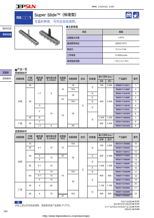
阿尔卑斯Super SlideTM(标准型)滑动电位器RS_1系列选型手册
6.6
个别对应规格
电阻规律
3B , 15C
防尘罩
可对应
抽头
可对应 但只限 中心位置
注 部分是本公司推荐规格。
绝缘操纵杆形状 B
30˚ 1.6
4.9 45˚ 25˚ 6
6.6
(1) L1
Unit:mm
t=2
L1 10 15
Unit:mm
旋转电位器
t=2
滑动电位器
L1 5
t=2
L1 10 15
普通型
L1
焊接条件
P.372 P.373 P.374 P.403
包装规格 托盘
行程 (mm) 15, 20
30
45
60
外形图
No.
深圳捷比信--高品质精密元件供应商
www.jepsun.com
Super SlideTM(标准型) RS □□ 1
电阻体数
单联 单联 / 2 联
单联 2联 单联 / 2 联
包装数(pcs.)
0.2W
0.1W
0.2W
0.1W
10A
15A
最高使用电压
行程
单联
1B
4B, 10A, 15A
15mm
100V AC, 10V DC
50V AC, 10V DC
20mm
30mm 45mm
200V AC, 10V DC
150V AC, 10V DC
60mm
1B, 3B
2联 4B, 10A, 15A
100V AC, 10V DC
Dual
2
混响器用
操作部的形状 / 操作部的长度(mm)
绝缘操纵杆
金属操纵杆
三姆斯·工业支持-3SK2诊断显示器说明书

FAQ 04/2016Working with the 3SK2 diagnostic displayEasy diagnosis and transferring of safety programS i e m e n s A G 2016 A l l r i g h t s r e s e r v e dThis entry is from the Siemens Industry Online Support. The general terms of use (/terms_of_use ) apply.Security informa-tionSiemens provides products and solutions with industrial security functions that support the secure operation of plants, solutions, machines, equipment and/or networks. They are important components in a holistic industrial securityconcept. With this in mind, Siemens’ products and solutions undergo continuous development. Siemens recommends strongly that you regularly check for product updates.For the secure operation of Siemens products and solutions, it is necessary to take suitable preventive action (e.g. cell protection concept) and integrate each component into a holistic, state-of-the-art industrial security concept. Third-party products that may be in use should also be considered. For more information about industrial security, visit /industrialsecurity . To stay informed about product updates as they occur, sign up for a product-specific newsletter. For more information, visit .Table of contents1 Product overview ............................................................................................... 5 2Controlling and monitoring .............................................................................. 6 2.1 Preparation in the software .................................................................. 8 2.1.1 Filling in of project information ............................................................. 8 2.1.2 Preparation for detailed status information ........................................ 10 2.2 Displaying of plant information ........................................................... 11 2.2.1 Reading out of project information ..................................................... 11 2.2.2 Reading out of status information ...................................................... 12 2.3 Fault diagnostic .................................................................................. 14 3Transferring of projects by the help of the diagnostic display (15)3.1 Preconditions ...................................................................................... 15 3.2 Procedure ........................................................................................... 17 3.3 Use cases ........................................................................................... 20 3.3.1 Fast device exchange ........................................................................ 20 3.3.2 Fast commissioning of same application . (21)4 Contact/Support (22)S i e m e n s A G 2016 A l l r i g h t s r e s e r v e dQuestionWhich functionality can be realized by the 3SK2 diagnostic display (MLFB 3SK2611-3AA00)?S i e m e n s A G 2016 A l l r i g h t s r e s e r v e dAnswerThe diagnostic display offers easy fault location without PC/PG. It supports fast problem solution by detailed fault messages. There is no engineering in advance in the basic module necessary to connect the display. The connection outside of the control cabinet allows easy access.Furthermore with two integrated memory slots you can use the diagnostic display for saving and transferring of projects. This simplifies commissioning of identical machinery and allows quick device exchange in case of fault. It is especially helpful by use of the 22,5 mm width basic module which has no exchangeable memory module.S i e m e n s A G 2016 A l l r i g h t s r e s e r v e d1Product overviewBeside the 3SK2 diagnostic display (MLFB 3SK2611-3AA00) the 3RK3 diagnostic display (MLFB 3RK3611-3AA00) still exists. The following table shows an overview of compatibility and functionality.Table 1: Compatibility diagnostic display 3SK2 and 3RK3It is not possible to transfer projects with the 3RK3 diagnostic display.For both displays you need a connection cable, which is available in different lengths and flat and round version: MLFB 3UF793*-0*A00-0.S i e m e n s A G 2016 A l l r i g h t s r e s e r v e d2Controlling and monitoringBesides the fault detection via monitoring function within the software, the diagnostic display helps for easy problem analysis without connection of PC or PG by detailed error messages. Even in case of no failure project and status information are helpful which are available at the display.In the following image you can see a simplified menu overview of the diagnostic display.Figure 1: Menu structure diagnostic displayS i e m e n s A G 2016 A l l r i g h t s r e s e r v e dMenu items have no fixed numbering and can be hidden in the display depending on the connected device and current status. The menu items …Status Info“, …Status“ and …Configuration Transmission “ are shown in detail as they are more relevant for this FAQ.In the menu item …Status “ the state of all in- and outputs can be read out (e.g. “Switching output Switching ON Condition not satisfied ”). Comprehensive project information (e.g. Config-CRC, Project Engineer) can be found in the menu item …System Configuration “. In case of troubleshooting the menu item …Status Info “ is helpful. Here you can see detailed error messages and warnings. All status information which are available in Safety ES can be shown at the display. If no errors are present the menu item is empty.By means of an example with guard door monitoring and emergency stop theeasy diagnose in case of fault and no fault will be shown subsequently.Figure 2: Logic plan application exampleS i e m e n s A G 2016 A l l r i g h t s r e s e r v e d2.1 Preparation in the softwareThere is no previous engineering of the diagnosis display in the software necessary. The display can be plugged in without any effort in advance.For easy error tracking it is helpful to assign informative names to the function elements which will be shown in the diagnostic display. Furthermore all added project / hardware information can be read out in the display.2.1.1 Filling in of project informationIn …Identification“ and …Configuration“ information regarding project and hardware configuration can be filled in.Figure 3: Filling in of project informationS i e m e n s A G 2016 A l l r i g h t s r e s e r v e dFigure 4: Filling in of hardware informationIn the main system the diagnostic display can be added on system slot 1 optionally. This is only for documentation purpose and is not mandatory. All project information can be found in the diagnostic display in the menu item …System C onfiguration“.S i e m e n s A G 2016 A l l r i g h t s r e s e r v e d2.1.2 Preparation for detailed status informationFor easy diagnose it is advisable to name the function elements.Figure 5: Naming of function elementsBy double-clicking on the respective function element a symbolic name can be assigned in the window …properties“. T his name is displayed as further information in the diagnostic display. It is helpful to assign names for all input elements (e.g. “Emergency Stop”) as well for all output elements (e.g. “F -output”).S i e m e n s A G 2016 A l l r i g h t s r e s e r v e d2.2Displaying of plant informationTo read out information at the diagnostic display an active connection to the energised basic module must be established. There mustn’t be any additional connection from the PCs/PGs via the diagnostic display to basic module. In this case the display is locked.2.2.1Reading out of project informationInformation regarding the project or hardware can be found in the menu item …System Configuration “. In the menu item …Project“ details regarding Config- CRC, Time Stamp, Release and Project Engineer are listed. Certain information are provided automatically from the system. Other information like …Project Engineer “ are only available if the corresponding fields were filled in in thesoftware (see chapter 2.1.1 Filling in of project information).In the menu item …Slot 3“ details regarding the used basic module can be found.Table 1: Project- and HardwareinformationS i e m e n s A G 2016 A l l r i g h t s r e s e r v e d2.2.2 Reading out of status informationThe full information concerning input and output elements can be found in the menu item …Status“.The elements are displayed as follows:Figure 6: Displaying of status/status infoFor this example the guard door is opened, the Emergency Stop was pushed and released but not acknowledged yet. Thus the output is not activated. These information can be read out in …Status / Input Elements “ as well …Status / Output Elements “.E-Stop 1 (symbolic name of the element),S i e m e nsA G 2016 A l l r i g h t s r e s e r v e dProtective Door (type of function element)You can read out status information which are available as element status in the Safety ES (e.g. …Timer running “, …Wa iting for Start“).S i e m e n s A G 2016 A l l r i g h t s r e s e r v e d2.3Fault diagnosticTroubleshooting with the help of the diagnostic display will be explained by means of the application example of figure 2. There is a cross circuit between input 1 and input 2 of the emergency stop with element number 1.In case of fault detailed information can be found in the menu item “Status Info “. According to the default setting of the display the status info will be directly shown on the start screen in case of a fault (Setting adjustable in …Display Settings/ Statu s Info“)Table 2: Error messages in case of Cross-CircuitThe same procedure applies to other faults like discrepancy fault or fault within the feedback circuit. Below the element you find then the error message ‚Dis crepancy violated ‘ or ‚Feedback Circuit invalid ‘. All element messages which are available in Safety ES can be shown on the diagnostic display as well.S i e m e n s A G 2016 A l l r i g h t s r e s e r v e d3Transferring of projects by the help of the diagnostic displayThe 3SK2 diagnostic display (MLFB: 3SK2611-3AA00) has two internal memory slots at which Safety ES projects can be stored.NoteThis functionality is only available for the diagnostic display 3SK2611-3AA00. The 3RK3 diagnostic display (MLFB: 3RK3611-3AA00) has no internal memory slots and it is not possible to connect it to the 3SK2.3.1PreconditionsTo be able to transfer Safety ES projects from or to the display an activeconnection to the running basic module must be established. Furthermore it is not possible to have an additional connection from the basic module to the PG/PC via the diagnostic display. In this case the display is locked. Transferring of projects is possible with both types of 3SK2 basic modules (3SK2112, 22,5mm width/ 3SK2122, 45 mm width) as well as with the 3RK3 Advanced and 3RK3 ASIsafe.Preconditions for saving projects in the diagnostic display/ reading configurations from the deviceTo save projects within the diagnostic display 2 memory slots are available. If a project was already stored on the selected memory slot and you read out a new configuration on the same memory slot, the old one will be replaced. There are no restrictions for reading out configurations. It is possible to read out not approved and approved configurations. The device can be in configuration or safety mode. If the protection level ‚write protection‘ was selected by password for the project which will be read out from the basic module, the protection level will be copied to the configuration in the display as well.S i e m e n s A G 2016 A l l r i g h t s r e s e r v e dHinweisThe protection level ‚Read Protection ‘ should not be activated in the basicmodule (3SK“/3RK3). In this case it is not possible to read out any configuration. Thus it is not possible to copy a project with Read Protection. This can be set after download via the Safety ES Tool.Preconditions for transferring of projects to the basic module It is possible to transmit a project to the device on condition that: - Device is running in configuring mode. - No password for device access is set.- The configuration on the basic module is not approved or there is no configuration on the basic moduleIf one of these conditions is not fulfilled the download of the project fails. In case that the download fails it is possible to download the project by resetting thebasic module to factory settings via reset button (See manual 3SK2 chapter 8.1/ manual 3RK3 chapter 6.4.4.5). Afterwards the device runs up in configuring mode and the project can be downloaded.DANGERAccidentally start possibleThe operator has to ensure that the configuration is downloaded to the correct machine, otherwise it can lead to a dangerous situation.NoteThe menu …factory settings“ in the diagnostic display refers only to the diagnostic display and not to the basic module. By executing the command the configurations in the diagnostic display among others will be deleted.S i e m e n s A G 2016 A l l r i g h t s r e s e r v e d3.2 ProcedureFor reading out a configuration from the basic module an active connection to it is necessary. Downloading a project from Safety ES to the diagnostic display is not possible without the basic module.Saving a configuration in the diagnostic displaySelect the favoured Memory Slot e.g.Table 3: Backup of a projectThe project is now saved in the selected memory slot in the diagnostic display.S i e m e n s A G 2016 A l l r i g h t s r e s e r v e dThe project information of the saved project (Name, Project Engineer, Company, Config-CRC, Time Stamp, Approval, Cycle Time …) can be read out in the corresponding memory slot.Transmission of a configuration from the diagnostic display to the basic moduleTable 4 Write project to deviceThe configuration is now saved in the basic module.The project information of the downloaded project (Name, Project Engineer, Company, Config-CRC, Time Stamp, Approval, Cycle Time …) can be read out in “System Configuration/ Project”.S i e m e n s A G 2016 A l l r i g h t s r e s e r v e dNoteWhen downloading an approved configuration to the basic module the device first stays in configuring mode. To change to safety mode turn off and on the basic module. After running up, the device changes automatically to safety mode.S i e m e n s A G 2016 A l l r i g h t s r e s e r v e d3.3Use cases3.3.1 Fast device exchangeIn case of a faulty basic module the approved configuration can be transferred fast and easily to the new basic module by the help of the diagnostic display. Thus the plant operation can continue quickly.Figure 7: Fast device exchange NoteBack up the Safety ES project straight after successful commissioning of the safety application to the diagnostic display.3 Transferring of projects by the help of the diagnostic displayWorking with the 3SK2 Diagnostic displayEntry-ID: 109482844, V1.0, 04/201621S i e m e n s A G 2016 A l l r i g h t s r e s e r v e d3.3.2 Fast commissioning of same applicationBy help of the possibility to download projects from the diagnostic display the commissioning of identical machinery can be sped up. After successful function test and approving once the safety program can be downloaded to the other machinery.Figure 8: Fast commissioning of identical machinery4 Contact/SupportWorking with the 3SK2 Diagnostic displayEntry-ID: 109482844, V1.0, 04/201622Si emensA G2016Al lrigh tsr ese rv ed4 Contact/SupportSiemens AGTechnical AssistanceTel: +49 (911) 895-5900Fax : +49 (911) 895-5907Mail: ******************************** Internet: www.siemens.de/automation/support-request。
阿尔卑斯4方向带中央按钮表面贴装按键 SKRH系列选型手册

烙铁头温度 350±5℃ 350±10℃
焊接时间 3s max. 3 +- 10 s
焊接次数 1 time
2 time max.
多功能 操作装置
浸焊方式的参考举例
系列
RKJXT1F, RKJXM RKJXL
预热
焊接面表面温度
加热时间
100℃ max.
2 min. max.
120℃ max.
70s max.
耐电压
300V AC for 1min. or 360V AC for 2s
方向动作力
40±25mN·m
A, B, C, D方向 30±20mN·m AB、BC、CD、DA方向
25±20mN·m
10±7mN·m
按动作力
5±2N
3±1.5N
4.5±1N
编码器锁扣
15±8mN·m 12±8mN·m
-
端子强度
ø0.75 hole
3.85 1.85
1 3.8
6.3 9.9
ø1.05 hole
2 5.8
8.5
电路图
A1 Center 2
C3
4B 5 Common 6D
422 ALPS产品选型资料来源:/product/alps/
焊接条件 P.429
▲
深圳捷比信--高品质精密元件供应商
401 × 401 × 214
外形图
ƅ 1 2 3
形状
4 5 6
˘
xhabc SKRHAAE010
7.35 1.8 2.14 1 8.6 SKRHABE010 SKRHACE010
7.45 1.85 2.17 1.6 8.7 SKRHADE010
- 1、下载文档前请自行甄别文档内容的完整性,平台不提供额外的编辑、内容补充、找答案等附加服务。
- 2、"仅部分预览"的文档,不可在线预览部分如存在完整性等问题,可反馈申请退款(可完整预览的文档不适用该条件!)。
- 3、如文档侵犯您的权益,请联系客服反馈,我们会尽快为您处理(人工客服工作时间:9:00-18:30)。
检测
按动
滑动
旋转
编码器
电源
切换式
柔感
按入
径向
包装规格
载带
电路图
2
4
1
3
2nd
1st
NEW
/product/alps/ALPS产品选型资料来源:
252
TACT Switch TM
检测按动
滑动旋转编码器电源切换式敏感
柔感按入表面贴装
径向
■产品系列一览
225
型敏感型
按入表面贴装系列SKQJ
SKQB
SKSH
SKRW
SKRM
SKRB
SKRR
SKQG
SKTC
SKSK
SKSD
照片特长——薄型
薄型·长寿命薄型双动作防水—●—○————●——防塵
●●○○○○○○●——操作方向
Toppush
——●●●●●●●●●Sidepush
●
●
—
————
——
—
—
外形尺寸(mm)
W 7.511.5 3.3□3.7
□4.5
□4.8
7.5□5.2
3.4 3.5
4.1D 7.8511.9 2.9
7 2.2 3.2
3.9
H
7.3
11.3
0.350.40.550.6
0.8
0.62
0.6
动作力适用范围
〜1N 参照个别产品页
1N〜2N 2N〜3N 3N〜4N 4N〜5N
行程(mm)0.25
0.3
0.15
0.15 / 0.2
0.25
参照个别产品页
接地端子———
—
—
—
—
—
—
●
●
使用温度范围ー20℃ to+70℃ー40℃ to+90℃ー30℃ to +85℃
车用产品—
●
——
—
●
—
○
—
—
—
生命周期最大额定50mA 12V DC 最小额定
10μA 1V DC
电性能
绝缘电阻
100M Ω min. 100V DC for 1min.
耐电压
250V AC for 1min.
100V AC for 1min.
250V AC for 1min.
100V AC for 1min.
250V AC for 1min.100V AC for 1min.
100V AC for 1min.
耐久
性能
耐振性能10 to 55 to 10Hz/分, 全振幅 1.5mm X, Y, Z 3方向 各2小时
寿命根据个别规定
耐环境性能
耐寒性能
ー30±2℃ for 96h ー40±2℃ for 96h ー30±2℃ for 96h 耐热性能80±2℃ for 96h
90±2℃ for 96h
80±2℃ for 96h
耐湿性能60±2℃, 90 to 95%RH for 96h 60±2℃, 90 to 95%RH for 1000h
60±2℃, 90 to 95%RH for 96h
页
237239245246247248249250252253254
W ∶横尺寸,不含端子部的最外围尺寸。
D ∶纵尺寸,不含端子部的最外部尺寸。
H ∶有高度的尺寸,多种类时其中最小尺寸。
注
1. 关于车用等大温度范围的要求,将个别作出应对,因此如有要求的,请予我公司商谈。
2. 表中的●符号表示适用于系列内的全部产品,表中的○符号表示适用于系列内的部分产品。
● 按动开关焊接条件 ・・・・・・・・・・・・・・・・・・・・・・・・・・・・・・・・・・・・・・・・・288● 按动开关使用时的注意事项 ・・・・・・・・・・・・・・・・・・・・・・・・・・・・・・・・・・・・・289/product/alps/
ALPS产品选型资料来源:
检测
按动
滑动
旋转
编码器
电源
切换式
288
1.加热方式 以远红外线加热的上下加热方式。
2.温度测量方式用 V0.1~ V0.2的CA(K)或CC(T)测量。
位置在焊连接部(铜箔面)测量。
固定方式采用耐热胶带。
3.温度分布
1. 上述条件,为印刷电路板的零部品表面的温度。
根据电路板的材质,大小,厚度等,电路板温度和开关表面温度会有很大的不同,
关于开关表面温度,也请在上述条件内使用。
2. 根据贴面焊槽的种类,条件不同结果不同,请事先充分进行确认之后使用。
注
回流焊时
适用于表面贴装型
180
150
(˚C )
1. 考虑清洗触摸开关时,请协商。
2. 请不要从触摸开关上面浸入助焊剂。
3. 请不要事前在开关端子及印刷电路板的零部件贴装面上涂助焊剂。
4. 进行第2次焊接时,应在开关回复到常温之后进行。
5. 请使用比重为0.81以上的助焊剂(田村化研(株)EC-19S-8 同等品)。
注
自动浸焊时
系列
/product/alps/
ALPS产品选型资料来源:。