2099, 规格书,Datasheet 资料
WP937GYW;中文规格书,Datasheet资料

Units mW mA mA
SPEC NO: DSAE9714 APPROVED: WYNEC
REV NO: V.5 CHECKED: Allen Liu
DATE: MAR/17/2011 DRAWN: J.Yu
PAGE: 2 OF 7 ERP: 1101008572
/
Package Dimensions
Notes: 1. All dimensions are in millimeters (inches). 2. Tolerance is ±0.25(0.01") unless otherwise noted. 3. Lead spacing is measured where the leads emerge from the package. 4. The specifications, characteristics and technical data described in the datasheet are subject to change without prior notice.
WP937GYW
SPEC NO: DSAE9714 APPROVED: WYNEC
REV NO: V.5 CHECKED: Allen Liu
DATE: MAR/17/2011 DRAWN: J.Yu
PAGE: 5 OF 7 ERP: 1101008572
/
SPEC NO: DSAE9714 APPYW Green
SPEC NO: DSAE9714 APPROVED: WYNEC
REV NO: V.5 CHECKED: Allen Liu
DATE: MAR/17/2011 DRAWN: J.Yu
飞利浦加热破壁料理机 HR2099 用户手册说明书
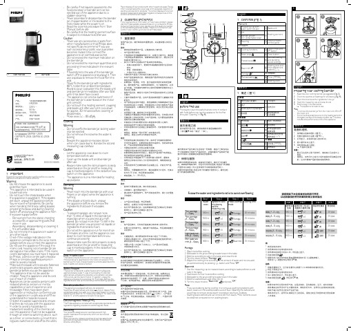
User manualSC 用户手册HR2091, HR2092, HR2098, HR2099, HR2199产品: 飞利浦加热破壁料理机型号: HR2099额定电压:220 V ~额定频率: 50 Hz 额定输入功率: 1000 W 生产日期: 请见产品底部 产地:中国广东东莞飞利浦(中国)投资有限公司 中国上海市静安区灵石路718 号A1 幢全国顾客服务热线:4008 800 008 本产品根据国标GB4706.1-2005, GB4706.19-2008, GB4706.30-2008制造9123456512346589107614526783(30 sec. – 3 min.)81243EnglishManual cooking mode (Fig. 5)1 Follow the steps in “Preparing your cooking blender”.2 Turn the rotary knob to the manual mode (step3 in Fig. 5).3Adjust the heating level by pressing -/+ button and then press OK button to confirm.4 Adjust the cooking time by pressing -/+ button.5Press OK button to start cooking.»When cooking is completed, you will hear a fewbeeps.6 Turn the rotary knob to “0” position.• The LED display will turn off if there is no operationin 5 minutes. You can wake up the appliance and continue operating by pressing any function key.7 Unplug the appliance.8 Remove the blender jar from the motor unit(step 11 in Fig. 5).• This allows the heating element to cool down faster. • Be aware that the lid and the blender jar will be hotafter cooking• Be aware of the steam release when you lift the lidand measuring cupWarning : Do not touch the bottom of blender jar and the heating element after cooking. It is very hot!9 Pour out the cooked ingredients/soup from the blenderjar to avoid overcooking.简体中文手动烹饪模式(图 5)1 按照“准备料理机”中的步骤操作。
0436500229;中文规格书,Datasheet资料
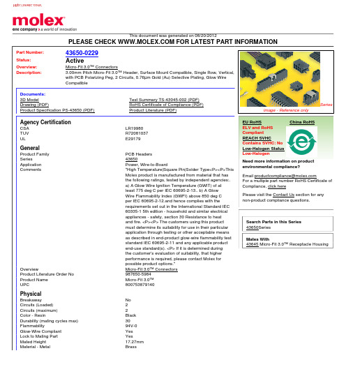
This document was generated on 08/20/2012PLEASE CHECK FOR LATEST PART INFORMATIONPart Number:43650-0229Status:ActiveOverview:Micro-Fit 3.0™ ConnectorsDescription:3.00mm Pitch Micro-Fit 3.0™ Header, Surface Mount Compatible, Single Row, Vertical,with PCB Polarizing Peg, 2 Circuits, 0.76µm Gold (Au) Selective Plating, Glow Wire CompatibleDocuments:3D ModelTest Summary TS-43045-002 (PDF)Drawing (PDF)RoHS Certificate of Compliance (PDF)Product Specification PS-43650 (PDF)Product Literature (PDF)Agency CertificationCSA LR19980TUV R72081037ULE29179GeneralProduct Family PCB Headers Series43650Application Power, Wire-to-BoardComments"High Temperature|Square Pin|Solder Type<P><P>This Molex product is manufactured from material that has the following ratings, tested by independent agencies:.a) A Glow Wire Ignition Temperature (GWIT) of at least 775 deg C per IEC 60695-2-13.. b) A Glow Wire Flammability Index (GWFI) above 850 deg C per IEC 60695-2-12.and hence complies with therequirements set out in the International Standard IEC 60335-1 5th edition - household and similar electrical appliances - safety, section 30 Resistance to heat and fire. <P><P> The customers using this product must determine its suitability for use in their particular application through testing or other acceptable means as described in end-product glow-wire flammability test standard IEC 60695-2-11 and any applicable product end-use standard(s). <P> If it is determined during the customer’s evaluation of suitability, that higher performance is required, please contact Molex for possible product options."OverviewMicro-Fit 3.0™ Connectors Product Literature Order No 987650-5984Product Name Micro-Fit 3.0™UPC800753879140PhysicalBreakawayNo Circuits (Loaded)2Circuits (maximum)2Color - ResinBlack Durability (mating cycles max)30Flammability94V-0Glow-Wire Compliant Yes Lock to Mating Part YesMated Height 17.27mm Material - MetalBrassSeriesimage - Reference onlyEU RoHSChina RoHSELV and RoHS Compliant REACH SVHCContains SVHC: No Low-Halogen Status Low-HalogenNeed more information on product environmental compliance?Email productcompliance@For a multiple part number RoHS Certificate of Compliance, click herePlease visit the Contact Us section for any non-product compliance questions.Search Parts in this Series 43650SeriesMates With43645 Micro-Fit 3.0™ Receptacle HousingMaterial - Plating Mating GoldMaterial - Plating Termination TinMaterial - Resin High Temperature ThermoplasticNet Weight0.461/gNumber of Rows1Orientation VerticalPC Tail Length 3.18mmPCB Locator YesPCB Retention NonePCB Thickness - Recommended 1.60mmPackaging Type TrayPitch - Mating Interface 3.00mmPlating min - Mating0.762µmPlating min - Termination 2.540µmPolarized to PCB YesShrouded FullyStackable NoSurface Mount Compatible (SMC)YesTemperature Range - Operating-40°C to +105°CTermination Interface: Style Through HoleElectricalCurrent - Maximum per Contact5AVoltage - Maximum250VSolder Process DataDuration at Max. Process Temperature (seconds)30Lead-free Process Capability SMC & Wave Capable (TH only)Max. Cycles at Max. Process Temperature3Process Temperature max. C260Material InfoReference - Drawing NumbersProduct Specification PS-43650Sales Drawing SD-43650-010Test Summary TS-43045-002This document was generated on 08/20/2012PLEASE CHECK FOR LATEST PART INFORMATION分销商库存信息: MOLEX 0436500229。
09060006420, 规格书,Datasheet 资料

Insertion and withdrawal force 32 way 40 N Materials
Mouldings Contacts Thermoplastic resin, glass-fibre filled, UL 94-V0 Copper alloy Selectively gold plated according to performance level1)
02.41
02 . 01
芯天下--/
Technical characteristics
Number of contacts
Type D Type E Type D Type E
Types D and E
Current carrying capacity
The current carrying capacity is limited by maximum temperature of materials for inserts and contacts including terminals. The current capacity curve is valid for continuous, non interrupts when simultaneous power on all contacts is given, without exceeding the maximum temperature. Control and test procedures according to DIN IEC 60 512
according to DIN 40 050
Removing the crimp contacts
The removal tool is inserted into a slot on the side of the respective crimp cavity. This action compresses the contact retaining spring therefore the contact can then be easily withdrawn using a light pull on the wire. This action will cause no damage to the contact/ wire which can be repositioned/refitted as necessary. The drawing demonstrates the crimp removal procedure (max. 5x). Removal tool
GB2099.3和GB2099.7-新标准解读
各位好:全国电器附件标委会2014年年会于2014年12月25日至26日在南京召开。
国标标准化委员会、CQC、当地政府、企业共150名代表参加了此次会议。
本次会议还审查了13项国家/行业标准,与我公司相关的标准有7项,其中最主要是GB2099.3《家用和类似用途插头插座第2-5部分:转换器的特殊要求》、GB2099.7《家用和类似用途插头插座第2-7部分:延长线插座的特殊要求》二项标准。
这几项标准与目前执行标准的主要差异是1)整体转换器按GB2099.3执行,延长线插座(原按GB2099.3执行的有线和无线转换器)按GB2099.7执行;2)延长线插座和转换器插座部分均需要带保护门且用L/N 极驱动;3)延长线插座配线加大,10A插座横截面积由原来的0.75mm2增加至1mm2;16A插座横截面积由原来的1mm2增加至1.5mm2;4)增加针焰试验;5)延长线插座孔形只能是国标孔或其组合孔;具体差异详见附件。
这些标准制定和修改的标准将会在今年(2015年)10月底批准,约三年后执行。
这些标准的实施将影响到我公司大部分产品的开发、生产和销售,请各部门提前做好准备。
附件一 GB 2099.3 新旧标准的对照表附件二 GB 2099.7 标准解读8.9增加下面新的条款:可拆线移动式插座提供关于怎样安全连接相应三芯软缆的充分说明,包括怎样从尾体上剥去绝缘的清晰说明。
可拆线插座需要提供关于怎样安全连接相应三芯软缆的充分说明,包括怎样从尾体上剥去绝缘的清晰的说明。
9尺寸检查9.1增加下述内容:移动式插座上允许将GB 1002标准2P插座插孔与2P+E插座插孔排列组合,但2P插座的插孔和2P+E插座的插孔不能相互重合或共用。
延长线插座可以用国标孔或其组合,但不能用其它孔型。
章节标准重要条款重点解读10防触电保护10.2 电线加长组件应设计和构造成,当它按正常使用要求安装和接好线后,带电部件是不易触及的,即使是那些不用工具便可拆下的部件被拆除之后也应如此。
0190850009;中文规格书,Datasheet资料

This document was generated on 08/10/2012PLEASE CHECK FOR LATEST PART INFORMATIONPart Number:19085-0009Status:ActiveOverview:Ring Tongue - Spade TerminalsDescription:Open Barrel Ring , Tin-Plated Steel, for 14-18 AWG Wire, Stud Size 10 (M5)Documents:Drawing (PDF)Product Specification PS-19902-011 (PDF)Product Specification PS-19902-006 (PDF)RoHS Certificate of Compliance (PDF)Agency CertificationCSA LR18689ULE32244GeneralProduct Family Ring and Spade Terminals Series19085Crimp Quality Equipment Yes Mil-Spec N/AOverviewRing Tongue - Spade Terminals Product Name N/A Type RingUPC800755080322PhysicalBarrel Type Open InsulationNone Material - Plating Mating Tin Net Weight0.770/g Packaging Type Reel Stud Size10 (M5)Temperature Range - Operating 149°C Wire Insulation Diameter N/AWire Size AWG 14, 16, 18Wire Size mm²0.80 - 2.00ElectricalVoltage - Maximum2000V Material InfoOld Part NumberRZ-S-4129-10Reference - Drawing NumbersProduct Specification PS-19902-006, PS-19902-011Sales DrawingSD-19085-002Series image - Reference onlyEU RoHSChina RoHSELV and RoHS Compliant REACH SVHC Not ReviewedLow-Halogen Status Not ReviewedNeed more information on product environmental compliance?Email productcompliance@For a multiple part number RoHS Certificate of Compliance, click herePlease visit the Contact Us section for any non-product compliance questions.Search Parts in this Series 19085SeriesApplication Tooling | FAQTooling specifications and manuals are found by selecting the products below.Crimp Height Specifications are then contained in the Application Tooling Specification document.GlobalDescription Product #ASP Perishable Tool Kit used in ASP presses that process metal strip product 0190290053Mini-Mac™Applicator0638815600This document was generated on 08/10/2012PLEASE CHECK FOR LATEST PART INFORMATION/分销商库存信息: MOLEX 0190850009。
EL2099中文资料

®FN7041EL2099Video Distribution AmplifierThe EL2099 is a high speed, monolithic operational amplifier*featuring excellent video performanceand high output current capability. Built using Elantec's Complementary Bipolar process, the EL2099 uses current mode feedback to achieve wide bandwidth, and is stable in unity gain configuration.Operation from power supplies ranging from ±5V to ±15V makes the EL2099 extremely versatile. With supplies at ±15V , the EL2099 can deliver ±11V into 25Ω at slew rates of 1000V/µs. At ±5V supplies, output voltage range is ±3V into 25Ω. Its speed and output current capability make this device ideal for video line driver and automatic test equipment applications.Differential Gain and Phase of the EL2099 are 0.03% and 0.05° respectively, and -3dB bandwidth is 50MHz. These features make the EL2099 especially well suited for video distribution applications.PinoutFeatures•50MHz -3dB bandwidth, A V = +2•Differential gain 0.03%•Differential phase 0.05°•Output short circuit current 800mA•Can drive six 75Ω double terminated cables ±11V •Slew rate = 1000V/µs•Wide supply voltage range ±5V to ±15VApplications•Video line driver •A TE pin driver•High speed data acquisitionTOP VIEWData Sheet January 1996, Rev. DO B S O L E T E P R O D U C TN O R E C O M M E N D E D R E P L A CE M E N T c o n t a c t o u r T e c h n i c a l S u p p o r t C e n t e r a t 1-888-I N T E R S I Lo r ww w .i n t e r s i l .c o m /t s c 元器件交易网Absolute Maximum Ratings (T A = 25°C)Voltage between V S + and V S -. . . . . . . . . . . . . . . . . . . . . . . . . .+33V Voltage at V S +. . . . . . . . . . . . . . . . . . . . . . . . . . . . . . . . . . . . +16.5V Voltage at V S - . . . . . . . . . . . . . . . . . . . . . . . . . . . . . . . . . . . . -16.5V Voltage between V IN + and V IN -. . . . . . . . . . . . . . . . . . . . . . . . . .±6VCurrent into V IN + or V IN -. . . . . . . . . . . . . . . . . . . . . . . . . . . . ±10mA Internal Power Dissipation. . . . . . . . . . . . . . . . . . . . . . . See Curves Operating Ambient T emperature Range . . . . . . . . . . . 0°C to +75°C Operating Junction T emperature . . . . . . . . . . . . . . . . . . . . . . .150°C Storage Temperature Range . . . . . . . . . . . . . . . . . .-65°C to +150°CNOTES:1.The input is moved from -10V to +10V.2.The supplies are moved from ±5V to ±15V.3.V IN = ±5V. See typical performance curve for larger values of V IN .CAUTION: Stresses above those listed in “Absolute Maximum Ratings” may cause permanent damage to the device. This is a stress only rating and operation of the device at these or any other conditions above those indicated in the operational sections of this specification is not implied.IMPORTANT NOTE:All parameters having Min/Max specifications are guaranteed. Typical values are for information purposes only. Unless otherwise noted, all tests are at the specified temperature and are pulsed tests, therefore: T J = T C = T AOpen-Loop DC Electrical SpecificationsV S = ±15V, R L = 25Ω, T A = 25°C unless otherwise specifiedPARAMETER DESCRIPTIONTEMP MINTYP MAX UNITS V OSInput Offset Voltage25°C 520mV T MIN , T MAX25mV TC V OS Average Offset Voltage Drift Full 20µV/°C +I IN+Input Current25°C 520µA T MIN , T MAX30µA -I IN-Input Current 25°C 835µA T MIN , T MAX50µA CMRR Common Mode Rejection Ratio (Note 1)25°C 5060dB PSRR Power Supply Rejection Ratio (Note 2)25°C 6070dB R OL Transimpedance25°C 85140k Ω+R IN+Input Resistance (Note 3)25°C 7001000k ΩT MIN , T MAX600k Ω+C IN +Input Capacitance 25°C 3pF CMIR Common Mode Input Range 25°C ±12.5V V OOutput Voltage Swing V S = ±15V 25°C ±9±11V Output Voltage Swing V S = ±5V25°C ±2.4±3.0V I OUT Output Current25°C 360440mA I SCOutput Short-Circuit Current25°C 600800mA T MIN , T MAX800mA I S Supply Current 25°C3245mANOTES:1.Slew Rate is with V OUT from +5V to -5V and measured at 20% and 80%.2.All AC tests are performed on a “warmed up” part, except for Slew Rate, which is pulse tested.3.Rise and Fall Times are with V OUT between -0.5V and +0.5V and measured at 10% and 90%.4.See typical performance curves for other conditions.Closed-Loop AC Electrical SpecificationsV S = ±15V, A V = +2, R F = 510Ω, R L = 25Ω, T A = 25°C unless otherwise specifiedPARAMETER DESCRIPTIONMIN TYP MAXUNITS SR Slew Rate (Note 1) (Note 2)5001000V/µs BW -3dB Bandwidth (Note 2)50MHz Peaking (Note 2)0.3dB t R , t F Rise Time, Fall Time (Note 2) (Note 3)7ns dG Differential Gain; DC Input Offset from 0V through +0.714V, AC Amplitude 286mV P-P , f = 3.58MHz (Note 4) (Note 2)0.03%dPDifferential Phase; DC Input Offset from 0V through +0.714V, AC Amplitude 286mV P-P , f = 3.58MHz (Note 2) (Note 4)0.05deg. (°)Typical Performance Curves (T A = 25°C, R L = 25Ω, A V = +2, R F = 510 unless otherwise specified)Non-InvertingFrequency Response (GAIN)Non-InvertingFrequency Response (PHASE)Inverting Frequency Response (GAIN)Inverting FrequencyResponse (PHASE)Frequency Response for Various C LFrequency Response for Various R LTypical Performance Curves (Continued)Transimpedance (R OL )Frequency Response for Various R F & R GPSRR & CMRR vs FrequencyClosed-Loop OutputImpedance vs FrequencyVoltage and Current Noise vs Frequency2nd and 3rd Harmonic Distortion vs FrequencyDie TemperatureTransimpedance (R OL) vs Die Temperature Input Current vsDie TemperatureOffset Voltage vs Die Temperature (4 Samples)PSRR & CMRR vs Die Temperaturefor Various R L s Voltage for Various R L sSlew Rate vs Supply Voltage Supply Current vs Supply Voltage+Input Resistance vs Input Voltage +Input Bias Current vs Input VoltageTypical Performance Curves (Continued)-3dB Bandwidth vs R F Peaking vs R FOvershoot vs R F Rise Time vs R F 5-Pin TO-220 Maximum Power Dissipation vs Ambient TemperatureSmall Signal Pulse ResponseLarge SignalPulse Response EL2099Simplified SchematicBurn-In CircuitApplications InformationProduct DescriptionThe EL2099 is a current mode feedback amplifier that has high output current drive capability. It is built using Elantec’s proprietary dielectric isolation process that produces NPN and PNP complimentary transistors. The high output current can be useful to drive many standard video loads in parallel, as well as digital sync pulses that are 8V or greater.+Input Resistor ValueA small value resistor located in the +Input pin is necessary to keep the EL2099 from oscillating under certain conditions.A 50Ω resistor is recommended for all applications, although smaller values will work under some circumstances. All tests listed in this datasheet are performed with 50Ω in the +Input pin, as well as all typical performance curves. The 50Ωresistor along with the +Input bias current creates an additional typical Offset Voltage of only 250µV at T = 25°C, and a maximum of 1.25mV over temperature variations.Feedback Resistor ValuesThe EL2099 has been designed and specified withR F=510Ω and A V = +2. This value of feedback resistor yields extremely flat frequency response with little to no peaking. However, 3dB bandwidth is reduced somewhat because of this. Wider bandwidth, at the expense of slight peaking, can be accomplished by reducing the value of the feedback resistor. For example, at a gain of +2, reducing the feedback resistor to 330Ω increases the -3dB bandwidth to 70MHz with 3dB of peaking. Inversely, larger values of feedback resistor will cause roll off to occur at a lower frequency. There is essentially no peaking with R F > 510Ω.Power SuppliesThe EL2099 may be operated with single or split supplies as low as ±5V (10V total) to as high as ±18V (36V total). Bandwidth and slew rate are almost constant fromV S=±10V to ±18V, and decrease slightly as supplies are reduced to ±5V, as shown in the characteristic curves. It is not necessary to use equal value split supplies. For example,-5V and -12V would be fine for 0V to 1V video signals.Good power supply bypassing should be used to reduce the risk of oscillation. A 1µF to 10µF tantalum capacitor inparallel with a 0.1µF ceramic capacitor is recommended for bypassing each supply pin. They should be kept as close as possible to the device pins.Due to the internal construction of the TO-220 package, the tab of the EL2099 is connected to the V S - pin. Therefore, care must be taken to avoid connecting the tab to the ground plane of the system.Printed Circuit Board LayoutAs with any high frequency device, good printed circuit board layout is necessary for optimum performance. Ground plane construction is highly recommended. Pin lengths should be as short as possible. For good AC performance, parasitic capacitances should be kept to a minimum, especially at the inverting input, which is sensitive to stray capacitance. This implies keeping the ground plane away from this pin. Metal film and carbon resistors are both acceptable, while use of wire-wound resistors is not recommended because of their parasitic inductance. Similarly, capacitors should be low inductance for best performance.Driving Cables and Capacitive LoadsThe EL2099 was designed with driving multiple coaxial cables in mind. With 440mA of output drive and low output impedance, driving six, 75Ω double terminated coaxial cables to ±11V with one EL2099 is practical.When used as a cable driver, double termination is always recommended for reflection-free performance. For those applications, the back termination series resistor willdecouple the EL2099 from the capacitive cable and allow extensive capacitive drive. For a discussion on some of the other ways to drive cables, see the application section on driving cables in the EL2003 data sheet.Other applications may have high capacitive loads without termination resistors. In these applications, an additional small value (5Ω-50Ω) resistor in series with the output will eliminate most peaking.The schematic below shows the EL2099 driving 6 double terminated cables, each of average length of 50 feet.This represents driving an effective load of 25Ω to over ±10V . The resulting performance is shown in the scopephoto. Notice that double termination results in reflection freeperformance.20ns/div5V / d i vEL2099EL2099EL2099 Macromodel* Connections: +input* | -input* | | +Vsupply* | | | -Vsupply* | | | | output* | | | | |.subckt M2099 4 5 1 3 2** Input Stage*e1 10 0 4 0 1.0vis 10 9 0Vh2 9 12 vxx 1.0r1 5 11 50l1 11 12 48nHiinp 4 0 5µAiinm 5 0 -8µA** Slew Rate Limiting*h1 13 0 vis 600r2 13 14 1Kd1 14 0 dclampd2 0 14 dclamp** High Frequency Pole**e2 30 0 14 0 0.00166713 30 17 1.5µHc5 17 0 1pFr5 17 0 500** Transimpedance Stage*g1 0 18 17 0 1.0ro1 18 0 150Kcdp 18 0 8pF** Output Stage*q1 3 18 19 qpq2 1 18 20 qnq3 1 19 21 qnq4 3 20 22 qpr7 21 2 1r8 22 2 1ios1 1 19 5mAios2 20 3 5mA** Supply Current*ips 1 3 19mA** Error Terms*ivos 0 23 5mAvxx 23 0 0Ve4 24 0 2 0 1.0e5 25 0 1 0 1.0All Intersil U.S. products are manufactured, assembled and tested utilizing ISO9000 quality systems.Intersil Corporation’s quality certifications can be viewed at /design/qualityIntersil products are sold by description only. Intersil Corporation reserves the right to make changes in circuit design, software and/or specifications at any time without notice. Accordingly, the reader is cautioned to verify that data sheets are current before placing orders. Information furnished by Intersil is believed to be accurate and reliable. However, no responsibility is assumed by Intersil or its subsidiaries for its use; nor for any infringements of patents or other rights of third parties which may result from its use. No license is granted by implication or otherwise under any patent or patent rights of Intersil or its subsidiaries.For information regarding Intersil Corporation and its products, see EL2099 Macromodel (Continued)e6 26 0 3 0 1.0r9 24 23 3Kr10 25 23 1Kr11 26 23 1K* Models*.model qn npn (is=5e-15 bf=200 tf=0.1nS).model qp pnp (is=5e-15 bf=200 tf=0.1nS).model dclamp d (is=1e-30 ibv=0.266 bv=5 n=4).ends。
0190350002;中文规格书,Datasheet资料

This document was generated on 08/13/2012PLEASE CHECK FOR LATEST PART INFORMATIONPart Number:19035-0002Status:ActiveDescription:Avikrimp™ Snap Plug, for 18-22 AWG Wire, Mylar Tape, 24.08mm LengthDocuments:Drawing (PDF)Product Specification PS-19902-015 (PDF)Product Specification PS-19902-011 (PDF)RoHS Certificate of Compliance (PDF)Agency CertificationCSA LR18689ULE152602GeneralProduct Family Quick Disconnects Series19035CommentsMolded Nylon Insulation Crimp Quality Equipment YesProduct Name Avikrimp™Type Snap PlugUPC800756403670PhysicalBarrel Type Closed Color - Resin Natural Flammability 94V-2GenderMale Glow-Wire Compliant NoInsulationNylon (PA)Lock to Mating Part None Material - MetalCopper Material - Plating MatingTin Material - Plating Termination Tin Material - Resin Nylon Net Weight 1.624/g OrientationStraightPackaging Type Adhesive Tape on Reel Tab Thickness N/A Tab WidthN/ATermination Interface: Style Crimp or Compression Wire Insulation Diameter 3.60mm max.Wire Size AWG 18, 20, 22Wire Size mm²0.35 - 0.80ElectricalVoltage - MaximumN/A Material InfoOld Part NumberA-559TReference - Drawing NumbersProduct Specification PS-19902-011, PS-19902-015Sales DrawingSD-19035-001Seriesimage - Reference onlyEU RoHSChina RoHSELV and RoHS Compliant REACH SVHC Not ReviewedLow-Halogen Status Not ReviewedNeed more information on product environmental compliance?Email productcompliance@For a multiple part number RoHS Certificate of Compliance, click herePlease visit the Contact Us section for any non-product compliance questions.Search Parts in this Series 19035SeriesApplication Tooling | FAQTooling specifications and manuals are found by selecting the products below.Crimp Height Specifications are then contained in the Application Tooling Specification document.GlobalDescription Product #Crimp Dies for MTA-100 Tape Applicator used in 3BF Press, MTA-105Tape Applicator used in TM-2000™ Press,and ATP-301 Air Crimping Press for Mylar Tape Mounted Terminals0192880004This document was generated on 08/13/2012PLEASE CHECK FOR LATEST PART INFORMATION/分销商库存信息: MOLEX 0190350002。