GZF15C中文资料
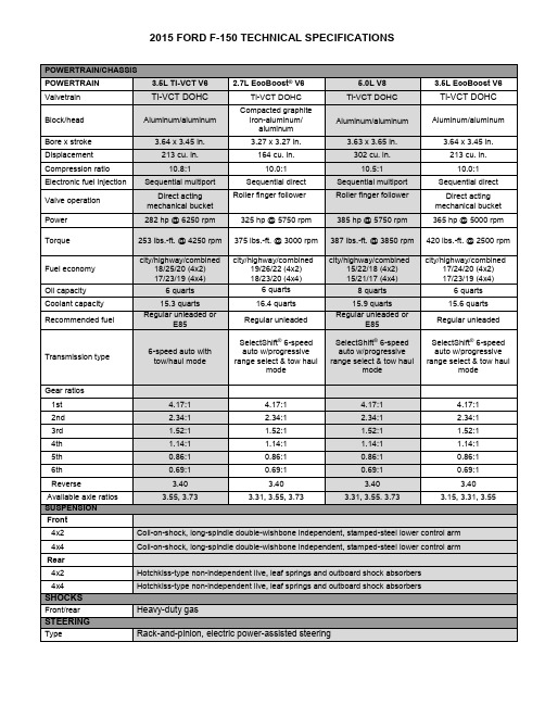
2015年福特F-150技术参数:发动机与车架说明书
243.7
Overall height
75.5 76.9 75.1 76.9 75.5 77.2 75.5 77.0 75.6 77.2 75.7
77.3
Overall width excl. mirrors
79.9 79.9 79.9 79.9 79.9 79.9 79.9 79.9 79.9 79.9 79.9
Compacted graphite iron-aluminum/ aluminum 3.27 x 3.27 in. 164 cu. in. 10.0:1 Sequential direct
Roller finger follower
325 hp @ 5750 rpm
Байду номын сангаас
5.0L V8 Ti-VCT DOHC
Front Rear Assist type
13.8 x 1.34 in., dual 2.1-in. pistons, non-asbestos organic linings 13.2 x 0.87 in. (electric parking brake) 13.7 x 0.98 in. (drum in hand), single 2.13-in. pistons, nonasbestos organic linings Vacuum, RSC
40.8
Rear
-
-
-
- 40.3 40.3 40.3 40.3 40.4 40.4 40.4
40.4
Legroom
Front (Max.)
43.9 43.9 43.9 43.9 43.9 43.9 43.9 43.9 43.9 43.9 43.9
43.9
福特F-150Expedition(2021年版):车载拖车系统说明说明书

Expedition: Standard Class IVSee chart below for the weight-carrying and weight-distributing capacities of this hitch receiver. (This capacity also is shown on a label affixed to each receiver.)Factory-Installed Trailer Hitch Receiver OptionsFrontal Area is the total area in square feet that a moving vehicle and trailer exposes to air resistance. The chart above shows the maximum trailer frontal area that must be considered for a vehicle/trailer combination. Exceeding these limitations may significantly reduce the performance of your towing vehicle.Frontal Area Limitations/ConsiderationsWithExpedition Base Trailer Frontal Area (55 sq. ft.)Without Heavy-Duty Trailer Tow Package60 sq. ft.With Heavy-Duty Trailer Tow PackageFrontal Area ConsiderationsWeight-Carrying Max. Max. Tongue Weight-Distributing Max. Max. Tongue VehicleTrailer Capacity (lbs.)(1) Load (lbs.) Trailer Capacity (lbs.)(1) Load (lbs.)Expedition 6,000 600 9,300 930Expedition MAX 6,300 630 9,000 900(1) Hitch receivers do not include a hitch ball or ball mounting. You are responsible for obtaining the proper hitch ball, ball mounting, weight-distributing equipment (i.e., equalizing arms and snap-up brackets, sway control system) and other appropriate equipment to tow both the trailer and its cargo load.Refer to the Trailer Towing Selector chart for Maximum Loaded Trailer Weights for this vehicle.Hitch Receiver Weight CapacityModelExpedition Expedition (Option Code)(Std.)(536)7-Wire Harness & 4-/7-Pin Connector X (Std.)Hitch Receiver X (Std.)Radiator Upgrade – X Electronic Traction Assist (eLSD) – X Upgraded Rear Axle – X 2-Speed Automatic 4WD–X(1)Trailer Brake Controller – X Trailer Sway Control X (Std.)Pro Trailer Backup Assist – X (1) 4x4 only.Trailer Towing PackageNotes: • C ontent may vary depending on model, trim and/or powertrain.See your dealer for specific content information.• T railer Towing Package recommended for all vehicles that willbe used for towing to help ensure easy, proper connection of trailer lights .2019 Ford ExpeditionRear Axle Non-Limited LimitedRatio S lip S lipExpedition 3.15 10 Not Available 3.31 15Not Available3.73Not Available3L (1)(1) Electronic Limited Slip axle.REVISED 12.21.18Automatic TransmissionMaximum Loaded Trailer Weight (lbs.)(1)Axle GCWR EXPEDITION EXPEDITION MAXWeight DistributionFor optimum handling and braking, the load must be properly distributed Keep center of gravity low for best handlingApproximately 60% of the allowable cargo weight should be in the front half of the trailer and 40% in the rear (within limits of tongue load or king pin weight)Load should be balanced from side-to-side to optimize handling and tire wear Load must be firmly secured to prevent shifting during cornering or braking, which could result in a sudden loss of controlBefore StartingBefore setting out on a trip, practice turning, stopping and backing up your trailer in an area away from heavy traffic Know clearance required for trailer roof Check equipment (make a checklist)Backing UpBack up slowly, with someone spotting near the rear of the trailer to guide you Place one hand at bottom of steering wheel and move it in the direction you want the trailer to goMake small steering inputs – slight movement of steering wheel results in much greater movement in rear of trailerTurningWhen turning, be sure to swing wide enough to allow trailer to avoid curbs and other obstructions.BrakingAllow considerably more distance for stopping with trailer attached Remember, the braking system of the tow vehicle is rated for operation at the GVWR, not GCWRIf your tow vehicle is an F-150, F-Series Super Duty ®, Transit or Expedition and your trailer has electric brakes, the optional Integrated Trailer Brake Controller (TBC) assists in smooth and effective trailer braking by powering the trailer’s electric or electric-over-hydraulic brakes with proportional output based on the towing vehicle’s brake pressure If you are experiencing trailer sway and your vehicle is equipped with electric brakes and a brake controller, activate the trailer brakes with the brake controller by hand. Do not apply the tow vehicle brakes as this can result in increased swayTowing On HillsDownshift the transmission to assist braking on steep downgrades and to increase power (reduce lugging) when climbing hillsWith TorqShift ® transmission, select tow/haul mode to automatically eliminate unwanted gear search when going uphill and help control vehicle speed when going downhillParking With A TrailerWhenever possible, vehicles with trailers should not be parked on a grade. However, if it is necessary, place wheel chocks under the trailer’s wheels, following the instructions below.Apply the foot service brakes and hold Have another person place the wheel chocks under the trailer wheels on the downgrade sideOnce the chocks are in place, release brake pedal, making sure the chocks will hold the vehicle and trailer Apply the parking brakeShift automatic transmission into park, or manual transmission into reverse With 4-wheel drive, make sure the transfer case is not in neutral (if applicable)Starting Out Parked On A GradeApply the foot service brake and hold Start the engine with transmission in park (automatic) or neutral (manual)Shift the transmission into gear and release the parking brakeRelease the brake pedal and move the vehicle uphill to free the chocks Apply the brake pedal while another person retrieves the chocksAcceleration And PassingThe added weight of the trailer candramatically decrease the acceleration of the towing vehicle – exercise caution.When passing a slower vehicle, be sure to allow extra distance. Remember, the added length of the trailer must clear the other vehicle before you can pull back in Signal and make your pass on level terrain with plenty of clearance If necessary, downshift for improved accelerationDriving With An Automatic Overdrive TransmissionWith certain automatic overdrive transmissions, towing – especially in hilly areas – may cause excessive shifting between overdrive and the next lower gear.To eliminate this condition and achieve steadier performance, overdrive can be locked out (see vehicle Owner’s Manual) If excessive shifting does not occur, use overdrive to optimize fuel economyOverdrive may also be locked out to obtain engine braking on downgrades When available, select tow/haul mode to automatically eliminate unwanted gear search and help control vehicle speed when going downhillDriving With Cruise ControlTurn off the cruise control with heavy loads or in hilly terrain. The cruise control may turn off automatically when you are towing on long, steep grades. Use caution while driving on wet roads and avoid using cruise control in rainy or winter weather conditions.Tire PressureUnderinflated tires get hot and may fail, leading to possible loss of vehicle control Overinflated tires may wear unevenly and compromise traction and stopping capabilityTires should be checked often for conformance to recommended cold inflation pressuresSpare Tire UseA conventional, identical full-size spare tire is required for trailer towing (mini, compact and dissimilar full-size spare tires should not be used; always replace the spare tire with a new road tire as soon as possible).On The RoadAfter about 50 miles, stop in a protected location and double-check:Trailer hitch attachment Lights and electrical connections Trailer wheel lug nuts for tightness Engine oil – check regularly throughout tripHigh Altitude OperationGasoline engines lose power by 3-4% per 1,000 ft. elevation. To maintainperformance, reduce GVWs and GCWs by 2% per 1,000 ft. elevation starting at the 1,000 ft. elevation point.Powertrain/Frontal Area ConsiderationsThe charts in this Guide show theminimum engine size needed to move the GCW of tow vehicle and trailer.Under certain conditions, however, (e.g., when the trailer has a large frontal area that adds substantial air drag or when trailering in hilly or mountainous terrain) it is wise to choose a larger engine Selecting a trailer with a low-drag, rounded front design will help optimize performance and fuel economyNote: F or additional trailering informationpertaining to your vehicle, refer to the vehicle Owner’s Manual.Towing a trailer is demanding on your vehicle, your trailer and your personal driving skills. Follow some basic rules that will help you tow safely and have a lot more fun.Photography, illustrations and information presented herein were correct when approved for publishing. Ford Motor Company reserves the right to discontinue or change at any time the specifications or designs without incurring obligation. Some features shown or described are optional at extra cost. Some options are required in combination with other options. Consult your dealer for the latest, most complete information on models, features, prices and availability.Many of the recreationalvehicles shown in this brochure are modified or manufactured by companies other than Ford Motor Company. Ford assumes no responsibility for such modifications or manufacturing.SAFETOWING FOR ALL VEHICLESFor the latest RV & Trailer Towing information, check out /towing-guides or go to .。
XGC55履带起重机技术规格书
XGC55履带起重机亮点介绍1.安全可靠的控制系统工作和安装两种操作模式方便可靠;紧急电气控制系统、安全及监控装置齐全。
高集成度的液压主阀,简化液压管路,使得故障点大大减少。
选配的旁路过滤系统,有效防止液压油乳化,延长系统元器件寿命。
2.卓越的操作性能创新性采用微控调节技术,大大提高整车动作的平稳性与精确度。
3.强大的起重能力主臂最大起重能力55t/3.7m,副臂最大起重能力11.4t/11m。
最长主臂52m,固定副臂最长组合43m+16m。
4.丰富的作业工况组合及工况轻松切换(选配功能)主臂工况、带臂端单滑轮及其吊钩的主臂工况、带固定副臂及其吊钩的主臂工况、固定副臂工况、带主臂吊钩的固定副臂工况、带主臂吊钩的臂端单滑轮工况,作业工况组合丰富且主副钩工况能实现一键轻松切换,满足各种吊装需求。
5.高效的作业效率丰富的组合动作和理想的单绳速度,作业轻松高效。
6.便捷的拆装功能配备人字架自扳起功能,无需辅助车辆,轻松实现人字架自扳起;臂架销轴双尖头及二重倒角技术,实现臂架拆装快捷高效。
7.灵活的配置组合发动机、泵、阀、机构、马达、回转支承等关键零部件均有国产和进口两种配置,主起升还有快放型配置,另有主臂走台板、监控系统、防雷击保护装置、电子水平仪、行走反向等多种功能可供用户选购,可满足不同用户群体需求。
8.模块化的部件设计百吨级以下XGC系列产品的固定副臂、臂端单滑轮、平衡重、吊钩能实现通用,可大大减少用户购买XGC系列产品的成本。
9.方便的维修技术需调整部位接近时间不大于10min/人,需日常保养部位接近时间不大于30 min/人,最长维修接近时间不大于2h/人;选配GPS远程监控系统方便用户进行设备维护与管理。
10.独具特色的外观造型XGC55是一款运用工业设计手段打造的全新造型产品。
仿生设计技术研发的新型操纵室外观时尚新颖,内饰与控制系统经过人体仿真软件模拟实验,操作更加便捷舒适,视野更宽广。
XGC55履带起重机技术规格书履带起重机型号:XGC55最大额定起重量:55t/3.7m最大额定起重力矩:203.5t.m一、产品的部件和系统描述一)上车部分1、臂架组合方式XGC55履带起重机的臂架为高强无缝钢管作为弦管和腹管,辅以高强钢板分段焊接成中间等截面,两端变截面的四弦管空间桁架结构。
2011-07-28康菱各系列发动机发电机型号说明
发展代号
发电用途(C:工程机械、M:船用)
排量:780立方英寸(12.8L) 中冷进气 AFTER COOLER 增压进气 TURBO CHANGE 系列号:P、Q
编产品辑系标列-题重庆科克(GOOGOL)
1.
康菱-HG重庆googol系列
2.
机组备用功率:220kW-2640kW
1004T-G
发电用途(C:工程机械、M:船用) 增压进气 TURBO CHANGE 1000系列,缸数4
编产品辑系标列-题韩国斗山大宇(DOOSAN)
1. 康菱-HD斗山大宇系列 2. 机组备用功率:150kW-620kW 3. 柴油机产地:韩国斗山集团 4. 柴油机系列: 5. P086 / P126 / P158 / P180 / P222
12. 4008TAG2A 13. 4012-46TWG2A 、G3A 、G4A 14. 4012-46TAG2A 、G3A 15. 4016TWG2 、4016TAG 、4016TAG1A 、G2A 、4016-61TRG3
2806C-E18TAG1A
发展代号:1/ 2 G:发电用途 A:空气中冷 T:增压进气 18:排量 18L / 15L / 13L E:电喷 C:排放受控 缸数 2800系列、2200、2500系列
N T A 855-G 1
发展代号 发电用途(C:工程机械、M:船用) 排量:855立方英寸(14L)\ 19L\ 38L 中冷进气 AFTER COOLER 增压进气 TURBO CHANGE 系列号:N、K、M、QSK
编产品辑系标列-题东风康明斯(CUMMINS)
1. 康菱-HC东风康明斯系列 2. 机组备用功率:22kW-220kW 3. 柴油机产地:湖北 4. 柴油机系列: 5. 4B3.9-G2、4BT3.9-G2、4BTA3.9-G2 6. 6BT5.9-G2、6BTA5.9-G2 、6BTAA5.9-G2 7. 6CTA8.3-G2 8. 6CTAA8.3-G2 9. 6LTAA8.9-G2
F-15C训练手册

Lock On: Modern Air Combat指导系列F-15C操作指导目录第一章 战机简介第二章 座舱第三章 HUD模式第四章 传感器第五章 雷达告警接受器第六章 空对空导弹第七章 武器使用3GO – 162/Eagle566编译2003-11-283GO侧卫战队第二飞行大队第一章战机简介1.1F-15 C“Eagle”F-15C“Eagle”战机常被称作是世界上最伟大的战斗机。
设计时的目标是对抗性能上言过其实的苏联米格-25战斗机。
F-15成为美国空军的主力战斗机已有近三十年的历史了。
与基本型F-15A相比,F-15C装备有增强的航电和武器系统,服役于以色列、沙特和美国,在各种局部战争中取得一百多次的空战胜利,而自己却没有被击落过一架。
F-15C在超视距空战(BVR)舞台上占有统治地位,在近距格斗中,也毫不示弱。
F-15C 擅长先发制人,首先发现目标,识别敌我,然后在敌机反应过来之前,以AIM-120和AIM-7导弹接战。
F-15C在近距离的格斗中稍微有些局限性。
AIM-9响尾蛇导弹,一种从六十年代就开始服役的可靠武器,与俄国的新式热追踪导弹相比,缺少大离轴角发射能力。
F-15战机的飞行员通常喜欢高速度的能量战斗而不是低速的转弯战斗,尤其在对抗灵活的敌机时。
机长: 63’ 9”机高: 18’ 8”翼展: 42’ 10”速度: Mach 2.5+ 海平面升限: 65,000’最大起飞重量: 68,000 lbs第二章座舱2.1.F-15C座舱尽管F-15C保留了一种名义上的对地攻击能力,但从严格意义上说,它是一架空中优势战斗机。
因此,它的座舱布局是围绕HUD下方的雷达显示屏和威胁告警装置显示屏而设计的。
下方的仪表面板则是聚焦于战机高度,引擎和贮存管理。
2.101垂直状况显示屏(VSD)垂直状况显示屏(VSD),换句话说,也就是“雷达显示屏”,占据着仪表面板的左上角。
VSD显示了战机前方空间的俯视图,被雷达探测到的飞机以亮点标出。
美国Eaton公司GF15W型号轻型GFCI保护插座说明说明书

Page 1 of 1Electrical Sector 1123 Hwy 74 SPeachtree City, GA 30269United States /SlimGFCIEaton1000 Eaton Boulevard Cleveland, OH 44122United States Eaton is a registered trademark. All other trademarks are property of their respective owners.© 2023 EatonAll Rights Reserved Printed in USAPublication No. TD610152ENSeptember 2023AlmondTRIP INDICATORSEOL Indicator LightRESET Button Light DiagnosisOFF OFF Device is functioning properly, OR branch circuit may not have power OFF ON Device is in tripped stateBlinking or ONONDevice is in “end of life” state and must be replacedAPPLICATIONS• Arrow Hart GFCI receptacles are UL Listed and fully compliant with all of the latest UL943 Class A GFCI and UL498 requirements• GFCI protection is required wherever receptacles are near wet or damp locations, such as public bathrooms, garages, and food service areas, and all other areas mandated by the NEC DESIGN FEATURES• Slimmer design for easy installation, leaving more room for wires in the box • Automatically self‑tests periodically to ensure GFCI protection• GFCIs incorporate lock‑out functionality to protect against mis‑wired line‑load connections and GFCI circuitry damage • Wider button wells for easy TEST and RESET• Intuitive LED status indicators for trip and end of life states• Clean, modern industrial design with reduced top housing markings and neutral text direction on buttons • Meets and exceeds 10 kA short circuit testing and Underwriters Laboratories (UL) UL943 safety standards • Automatic grounding system eliminates need for bonding jumper in grounded metal enclosure, provides redundant measure of ground continuity where jumper is used • External backwire clamps provide visual confirmation of secure termination • Line side terminals are backed out and staked for fast installation COMPLEMENTARY PRODUCTSWallplatesPJS26, PJS262ADDITIONAL RESOURCESScan QR code for additionalmarketing collateralArrow Hart WebsiteBuyer’s Guide Product pageMATERIALS Housing Top: Thermoplastic, polycarbonate Bottom: Thermoplastic, PVC Strap 0.042” thick steel, zinc‑plated Line contacts 0.030” thick brass Terminal Brass/nickel‑plated steelSPECIFICATIONS ElectricalDielectric voltage: Withstands 2000V per UL 498Current interrupting: Yes, at full‑rated current Temperature rise: Max. 30ºC (86°F) after100 cycles of overload @ 150% of rated current (DC)Trip time: 0.025 seconds (Class A)Frequency: 60 Hz; Voltage: 125V; Amperage: 15A/20A, 20A feed‑throughShort circuit testing: Meets and exceeds 10 kA Maximum interrupting capacity: 20 Amps Testing & code compliance cULus Listed to UL 498 and UL 943, file no. E60120Meets all UL 943 (GFCI), UL 498 (receptacles) and applicable CSA requirements; NOM certified; Federal Specification W‑C‑596H for 20A models Environmental Flammability: Meets UL 94 requirements; V2 rated Temperature rating: ‑35ºC to 66ºC (‑31ºF to 150.8ºF)Mechanical Terminal accommodation: #14 ‑ 10 AWG Voltage ratings: Permanently marked on deviceDESCRIPTION2-pole, 3-wire grounding 15A, 125V/AC 20A, 125V/ACSTANDARD GFCI RECEPTACLES, BACK & SIDE WIRERating A V/ACNEMA Catalog no.Color suffixFeatures151255‑15R ☐GF15__B, BK, GY, LA, V, W 151255‑15R ☐GF15__–WP BK, WIncludes standard size wallplate201255‑20R ☐GF20__*B, BK, GY, LA, RD, V, WWallplate not included unless specifically stated; *FedSpec certification on 20A only.Project Name:Prepared By:Project Number:Date:Catalog Number:Type:。
SMCJ15CA中文资料

GDE(BDE) GDG(BDG) GDK(BDK) GDM(BDM) GDP(BDP) GDR(BDR) GDT(BDT) GDV(BDV) GDX(BDX) GDZ(BDZ) GEE(BEE) GEG(BEG) GEK(BEK) GEM(BEM) GEP(BEP) GER(BER) GET(BET) GEV(BEV) GEX(BEX) GEZ(BEZ) GFE(BFE) GFG(BFG) GFK(BFK) GFM(BFM) GFP(BFP) GFR(BFR) GFT(BFT) GFV(BFV) GFX(BFX) GFZ(BFZ) GGE(BGE) GGG(BGG) GGK(BGK) GGM(BGM) GGP(BGP) GGR(BGR) GGT(BGT) GGV(BGV) GGX(BGX) GGZ(BGZ) GHE(BHE) GHG(BHG) GHK(BHK) GHM(BHM) GHP(BHP) GHR(BHR)
(Note 1)
Value
minimum 1500 see table 200 -55 to +150 -55 to +150
Units
W A A °C °C
*These ratings are limiting values above which the serviceability of any semiconductor device may be impaired.
Max Reverse Leakage VRWM IR (uA)*
SMCJ5.0(C)A SMCJ6.0(C)A SMCJ6.5(C)A SMCJ7.0(C)A SMCJ7.5(C)A SMCJ8.0(C)A SMCJ8.5(C)A SMCJ9.0(C)A SMCJ10(C)A SMCJ11(C)A SMCJ12(C)A SMCJ13(C)A SMCJ14(C)A SMCJ15(C)A SMCJ16(C)A SMCJ17(C)A SMCJ18(C)A SMCJ20(C)A SMCJ22(C)A SMCJ24(C)A SMCJ26(C)A SMCJ28(C)A SMCJ30(C)A SMCJ33(C)A SMCJ36(C)A SMCJ40(C)A SMCJ43(C)A SMCJ45(C)A SMCJ48(C)A SMCJ51(C)A SMCJ54(C)A SMCJ58(C)A SMCJ60(C)A SMCJ64(C)A SMCJ70(C)A SMCJ75(C)A SMCJ78(C)A SMCJ85(C)A SMCJ90(C)A SMCJ100(C)A SMCJ110(C)A SMCJ120(C)A SMCJ130(C)A SMCJ150(C)A SMCJ160(C)A SMCJ170(C)A
SMF15C中文资料

SMF05C, SMF12C, SMF15C,SMF24C5−Line Transient Voltage Suppressor ArrayThis 5−line voltage transient suppressor array is designed for application requiring transient voltage protection capability. It is intended for use in over−transient voltage and ESD sensitive equipment such as computers, printers, automotive electronics,networking communication and other applications. This device features a monolithic common anode design which protects five independent lines in a single SC−88 package.Features•Protects up to 5−Line in a Single SC−88 Package•Peak Power Dissipation − 100 W (8 x 20 m s Waveform)•ESD Rating of Class 3B (Exceeding 8 kV) per Human Body Model and Class C (Exceeding 400 V) per Machine Model.•Compliance with IEC 61000−4−2 (ESD) 15 kV (Air), 8 kV (Contact)•Flammability Rating of UL 94 V−0•Pb−Free Package is Available Applications•Hand−Held Portable Applications •Networking and Telecom •Automotive Electronics •Serial and Parallel Ports•Notebooks, Desktops, ServersMAXIMUM RATINGS (T J =25°C unless otherwise specified)Maximum ratings are those values beyond which device damage can occur.Maximum ratings applied to the device are individual stress limit values (not normal operating conditions) and are not valid simultaneously. If these limits are exceeded, device functional operation is not implied, damage may occur and reliability may be affected.1.Nonrepetitive current pulse per Figure 3.DevicePackage Shipping †ORDERING INFORMATIONSMF05CT1SC−883000/T ape & Reel SMF12CT1SC−883000/T ape & Reel SMF15CT1SC−883000/T ape & Reel SMF24CT1SC−883000/T ape & Reel†For information on tape and reel specifications,including part orientation and tape sizes, please refer to our Tape and Reel Packaging Specification Brochure, BRD8011/D.*The “T2” suffix refers to an alternate tape & reel orientation.SMF05CT2*SC−883000/T ape & Reel SMF05CT2G*SC−88(Pb−Free)3000/T ape & ReelSMF05C ELECTRICAL CHARACTERISTICS (T J = 25°C unless otherwise specified)SMF12C ELECTRICAL CHARACTERISTICS (T J = 25°C unless otherwise specified)SMF15C ELECTRICAL CHARACTERISTICS (T = 25°C, unless otherwise specified)SMF24C ELECTRICAL CHARACTERISTICS (T = 25°C, unless otherwise specified)S devices are normally selected according to the working peak reverse voltage (V RWM), which should be equal or greater than the DCor continuous peak operating voltage level.3.V BR is measured at pulse test current I T.TYPICAL PERFORMANCE CURVES(T J = 25°C unless otherwise specified)Figure 1. Pulse Derating Curve10090807060504030201000255075100125175200T A , AMBIENT TEMPERATURE (°C)Figure 2. 8 × 20 m s Pulse Waveform1009080706050403020100t, TIME (m s)% O F P E A K P U L S E C U R R E N TFigure 3. Clamping Voltage vs Peak Pulse Current 100101I PP , PEAK PULSE CURRENT (A)V C L A M P , C L A M P I N G V O L T A G E (V )Figure 4. Junction Capacitance vs Reverse VoltageV BR , REVERSE VOLTAGE (V)P E A K P O W E R D I S S I P A T I O N (%)PACKAGE DIMENSIONSSTYLE 24:PIN 1.CATHODE2.ANODE3.CATHODE4.CATHODE5.CATHODE6.CATHODENOTES:1.DIMENSIONING AND TOLERANCING PER ANSI Y14.5M, 1982.2.CONTROLLING DIMENSION: INCH.3.419B−01 OBSOLETE, NEW STANDARD 419B−02.DIM A MIN MAX MIN MAX MILLIMETERS 1.80 2.200.0710.087INCHES B 1.15 1.350.0450.053C 0.80 1.100.0310.043D 0.100.300.0040.012G 0.65 BSC 0.026 BSC H −−−0.10−−−0.004J 0.100.250.0040.010K 0.100.300.0040.012N 0.20 REF 0.008 REF S2.00 2.200.0790.087SC−88/SC70−6/SOT−363CASE 419B−02ISSUE 02U*For additional information on our Pb−Free strategy and solderingdetails, please download the ON Semiconductor Soldering and Mounting Techniques Reference Manual, SOLDERRM/D.SOLDERING FOOTPRINT*ON Semiconductor and are registered trademarks of Semiconductor Components Industries, LLC (SCILLC). SCILLC reserves the right to make changes without further notice to any products herein. SCILLC makes no warranty, representation or guarantee regarding the suitability of its products for any particular purpose, nor does SCILLC assume any liability arising out of the application or use of any product or circuit, and specifically disclaims any and all liability, including without limitation special, consequential or incidental damages.“Typical” parameters which may be provided in SCILLC data sheets and/or specifications can and do vary in different applications and actual performance may vary over time. All operating parameters, including “Typicals” must be validated for each customer application by customer’s technical experts. SCILLC does not convey any license under its patent rights nor the rights of others. SCILLC products are not designed, intended, or authorized for use as components in systems intended for surgical implant into the body, or other applications intended to support or sustain life, or for any other application in which the failure of the SCILLC product could create a situation where personal injury or death may occur. Should Buyer purchase or use SCILLC products for any such unintended or unauthorized application, Buyer shall indemnify and hold SCILLC and its officers, employees, subsidiaries, affiliates,and distributors harmless against all claims, costs, damages, and expenses, and reasonable attorney fees arising out of, directly or indirectly, any claim of personal injury or death associated with such unintended or unauthorized use, even if such claim alleges that SCILLC was negligent regarding the design or manufacture of the part. SCILLC is an Equal Opportunity/Affirmative Action Employer. This literature is subject to all applicable copyright laws and is not for resale in any manner.PUBLICATION ORDERING INFORMATION。
- 1、下载文档前请自行甄别文档内容的完整性,平台不提供额外的编辑、内容补充、找答案等附加服务。
- 2、"仅部分预览"的文档,不可在线预览部分如存在完整性等问题,可反馈申请退款(可完整预览的文档不适用该条件!)。
- 3、如文档侵犯您的权益,请联系客服反馈,我们会尽快为您处理(人工客服工作时间:9:00-18:30)。
Document Number 17249Zener DiodesFeatures•Silicon Planar Power Zener Diodes. •Low profile surface-mount package. •Low leakage current •High temperature soldering:260°C/10 sec. at terminalsMechanical DataCase: JEDEC DO-219AB (SMF ®) Plastic CasePackaging codes/options:GS18 - 10 K per 13 " reel, (8 mm tape), 50 K/box GS08 - 3 K per 7 " reel, (8 mm tape), 30 K/box Weight: approx. 0.01 gAbsolute Maximum RatingsT amb = 25°C, unless otherwise specified1) Mounted on epoxy glass PCB with 3 x 3 mm, Cu pads (≥ 40 µm thick)Thermal CharacteristicsT amb = 25°C, unless otherwise specified1) Mounted on epoxy glass PCB with 3 x 3 mm, Cu pads (≥ 40 µm thick)ParameterTest conditionSymbolValue UnitZener current (see Table "Characteristics")see page 2Power dissipationT A = 25°CP tot8001)mW ParameterTest condition Symbol Value Unit Thermal resistance junction to ambient air1)R θJA 180K/W Maximum junction temperature T j 150°C Storage temperature rangeT STG- 55 to + 150°C Document Number 85769Electrical CharacteristicsMaximum V F = 1.2 V at I F = 200 mA1) Pulse test: tp ≤ 5 msPartnumberMarking CodeZener Voltage Range 1)Differential Resistance Temperature Coefficient T est Current Reverse Current at Reverse Voltage V Z @ I ZTr dif @ I ZαZ @ I Z I ZT I R V R VΩ%/°C mA µA Vminmax typ max min max max GZF3V6C W5 3.4 3.848-0.14-0.041001001GZF3V9C W6 3.7 4.148-0.14-0.04100501GZF4V3C W74 4.647-0.12-0.02100251GZF4V7C W8 4.4537-0.10100101GZF5V1C W9 4.8 5.436-0.08-0.210051GZF5V6C WA 5.2624-0.040.04100102GZF6V2C WB 5.8 6.623-0.010.0610052GZF6V8C WC 6.47.21300.07100103GZF7V5C WD 77.91200.07100503GZF8V2C WE 7.78.7120.030.08100103GZF9V1C WF 8.59.6240.030.0850105GZF10C WG 9.410.6240.050.095077.5GZF11C WH 10.411.6470.050.15048.2GZF12C WI 11.412.7470.050.15039.1GZF13C WK 12.414.15100.050.150210GZF15C WL 13.815.65100.050.150111GZF16C WM 15.317.16150.060.1125112GZF18C WN 16.819.16150.060.1125113GZF20C WO 18.821.26150.060.1125115GZF22C WP 20.823.36150.060.1125116GZF24C WR 22.825.67150.060.1125118GZF27C WS 25.128.97150.060.1125120GZF30C WT 28328150.060.1125122GZF33C WU 31358150.060.1125124GZF36C WW 343821400.060.1110127GZF39C WX 374121400.060.1110130GZF43C WY 404624450.070.1210133GZF47C WZ 445024450.070.1210136GZF51C X1485425600.070.1210139GZF56C X2526025600.070.1210143GZF62C X3586625800.080.1310147GZF68C X4647225800.080.1310151GZF75C X57079301000.080.1310156GZF82C X67787301000.080.1310162GZF91CX78596602000.090.135168Document Number Typical Characteristics (T amb = 25 °C unless otherwise specified)Figure 1. Forward characteristicsFigure2. Admissible Power Dissipation vs. Ambient TemperatureFigure3. Capacitance vs. Zener Voltage17364I V F0.410101010101010101-2-3-53mAP80060040020017365V217366Package Dimensions in mm Document Number 85769Blistertape für SMFDocument Number Ozone Depleting Substances Policy StatementIt is the policy of Vishay Semiconductor GmbH to1.Meet all present and future national and international statutory requirements.2.Regularly and continuously improve the performance of our products, processes, distribution andoperatingsystems with respect to their impact on the health and safety of our employees and the public, as well as their impact on the environment.It is particular concern to control or eliminate releases of those substances into the atmosphere which are known as ozone depleting substances (ODSs).The Montreal Protocol (1987) and its London Amendments (1990) intend to severely restrict the use of ODSs and forbid their use within the next ten years. Various national and international initiatives are pressing for an earlier ban on these substances.Vishay Semiconductor GmbH has been able to use its policy of continuous improvements to eliminate the use of ODSs listed in the following documents.1.Annex A, B and list of transitional substances of the Montreal Protocol and the London Amendmentsrespectively2.Class I and II ozone depleting substances in the Clean Air Act Amendments of 1990 by the EnvironmentalProtection Agency (EPA) in the USA3.Council Decision 88/540/EEC and 91/690/EEC Annex A, B and C (transitional substances) respectively. Vishay Semiconductor GmbH can certify that our semiconductors are not manufactured with ozone depleting substances and do not contain such substances.We reserve the right to make changes to improve technical designand may do so without further notice.Parameters can vary in different applications. All operating parameters must be validated for each customer application by the customer. Should the buyer use Vishay Semiconductors products for any unintended or unauthorized application, the buyer shall indemnify Vishay Semiconductors against all claims, costs, damages, and expenses, arising out of, directly or indirectly, any claim of personal damage, injury or death associated with such unintended or unauthorized use.Vishay Semiconductor GmbH, P.O.B. 3535, D-74025 Heilbronn, GermanyTelephone: 49 (0)7131 67 2831, Fax number: 49 (0)7131 67 2423 Document Number 85769。