ELLS-326RWA中文资料
拉雷尔电子有限公司产品说明书

LAUREL ELECTRONICS, ureate™ Rate Meter & Totalizer with Functions A+B, A-B, AxB, A/B, A/B-1Features•Arithmetic functions A+B, A-B, AxB, A/B, A/B-1 applied to rate or total forchannels A & B•Frequencies from 0.005 Hz to 10 kHz•Independent scaling for each channel•Selectable "count by" of 10 or 100 with rounding•6-digit red or green LED display•Universal AC power Input, 85-264 Vac•Isolated 5, 10 or 24 Vdc excitation output•NEMA 4X, 1/8 DIN case•Optional serial I/O: Ethernet, USB, RS232, RS485, Ethernet-to-RS485 converter•Optional relay outputs: dual or quad relays, contact or solid state•Optional isolated analog output: 4-20 mA, 0-20 mA, 0-10V, -10 to +10V•Optional low voltage power: 10-48 Vdc or 12-32 VacDescriptionArithmetic functions A+B, A-B, AxB, A/B, A/B-1 applied tochannels A & B are a capability of Laureates with an Extendedcounter main board and FR dual-channel signal conditionerboard. These functions are applicable to rate or total after scalingto engineering units. The following are application examples:•Add two flows (A+B) for total flow or total volume.•Subtract two flows (A-B) for net flow or net volume.•Take the ratio of two flow rates (A/B) for chemical mixing.•Take the ratio of RPMs or belt speeds (A/B) to synchronizemoving machinery.•Subtract 1 from ratio (A/B-1) to control elongation of materialcompressed by rollers (draw).•Multiply belt speed by weight of material on the belt to for rateor weight of material delivered by the belt. A weighttransducer with frequency output is required.Ratio and draw are similar, except that 1 is subtracted from ratioto obtain draw. The frequency of channels A or B is measuredand converted to rate in engineering units by multiplying it by theappropriate scale factor for that channel. Either rate can bedisplayed. The A/B ratio is taken mathematically by the meter,and 1 is subtracted for draw. The result can be multiplied by amultiple or 10 from 0.0001 to 100000, and the decimal point canbe set to display the result with the desired precision up to sixdigits.Fast, High Resolution Measurements. Laureate countersdetermine frequency by timing an integral number of periods overa programmable gate time. The inverse period approach allowsgreater accuracy and faster update times than conventionalmeters which count signal pulses over a specified time interval.Channel A accepts pulses from 0.005 Hz to 1 MHz, while Chan-nel B accepts pulses from 0.005 Hz to 250 kHz. At the minimumgate time of 10 ms, update rates can be up to 25/second. Suchfast response is ideal for peak capture and for alarm and controlapplications. Variations in the displayed reading can be reducedby selecting a longer gate time. An adaptive digital filter canfurther reduce variations due to noise while rapidly responding toactual changes in the signal.Universal Signal Conditioner. The Laureate dual-channelsignal conditioner accepts inputs from proximity switches withPNP or NPN output, TTL or CMOS logic, magnetic pickups,contact closures, low-level outputs from turbine flow meters downto 12 mV, or high-level AC line inputs to 250 Vac. Jumper selec-tions provide optimum operation for different sensor types andnoise conditions. A built-in isolated 5, 10, or 24 Vdc excitationsupply can power proximity switches or other sensors, andeliminate the need for an external power supply.Designed for system use. Optional plug-in boards includeEthernet and other serial communication boards, dual or quadrelay boards, and an isolated analog output board. Laureatesmay be powered from 85-264 Vac or optionally from 12-32 Vacor 10-48 Vdc. The display is available with red or green LEDs.The 1/8 DIN case meets NEMA 4X (IP65) specifications from thefront when panel mounted. Any setup functions and front panelkeys can be locked out for simplified usage and security. A built-in isolated 5, 10, or 24 Vdc excitation supply can power trans-ducers and eliminate the need for an external power supply.All power and signal connections are via UL / VDE / CSA ratedscrew clamp plugs.SpecificationsDisplayReadout Display Range Zero Adjust Span Adjust Indicators 6 LED digits, 7-segment, 14.2 mm (.56"), red or green LED -999999 to +999999, XXXXEX notation beyond 999999-999999 to +9999990 to 999999Four LED lampsInputsTypesSignal Ground Channel A Frequency Channel B Frequency Minimum Signal Maximum Signal Noise FilterContact Debounce AC, pulses from NPN, PNP transistors, contact closures, magnetic pickups Common ground for channels A & B0.005 Hz to 1 MHz0.005 Hz to 250 kHzNine ranges from (-12 to +12 mV) to (+1.25 to +2.1V)250 Vac1 MHz, 30 kHz, 250 Hz (selectable)0, 3, 50 ms (selectable)Rate AccuracyTime Base Span Tempco Long-term Drift Crystal calibrated to ±2 ppm ±1 ppm/°C (typ)5 ppm/yearPowerVoltage, standard Voltage, optional Power frequency Power consumption (typical, base meter) Power isolation 85-264 Vac or 90-300 Vdc12-32 Vac or 10-48 VdcDC or 47-63 Hz1.2W @ 120 Vac, 1.5W @ 240 Vac, 1.3W @ 10 Vdc, 1.4W @ 20 Vdc, 1.55W @ 30 Vdc, 1.8W @ 40 Vdc,2.15W @ 48 Vdc250V rms working, 2.3 kV rms per 1 min testExcitation Output (standard)5 Vdc10 Vdc24 VdcOutput Isolation 5 Vdc ± 5%, 100 mA10 Vdc ± 5%, 120 mA 24 Vdc ± 5%, 50 mA50 Vdc to meter groundAnalog Output (optional)Output Levels Current compliance Voltage compliance Scaling Resolution Isolation 4-20 mA, 0-20 mA, 0-10V, -10 to +10V (single-output option) 4-20 mA, 0-20 mA, 0-10V (dual-output option)2 mA at 10V ( > 5 kΩ load)12V at 20 mA ( < 600Ω load)Zero and full scale adjustable from -99999 to +9999916 bits (0.0015% of full scale)250V rms working, 2.3 kV rms per 1 min test(dual analog outputs share the same ground)Relay Outputs (optional)Relay Types Current Ratings Output common Isolation 2 Form C contact relays or 4 Form A contact relays (NO)2 or 4 Form A, AC/DC solid state relays (NO)8A at 250 Vac or 24 Vdc for contact relays120 mA at 140 Vac or 180 Vdc for solid state relays Isolated commons for dual relays or each pair of quad relays 250V rms working, 2.3 kV rms per 1 min testSerial Data I/O (optional)Board Selections ProtocolsData Rates Digital Addresses Isolation Ethernet, Ethernet-to-RS485 converter, USB, USB-to-RS485 converter, RS485 (dual RJ11), RS485 Modbus (dual RJ45), RS232.Modbus RTU, Modbus ASCII, Laurel ASCII protocol300 to 19200 baud247 (Modbus), 31 (Laurel ASCII),250V rms working, 2.3 kV rms per 1 min testEnvironmental Operating Temp. Storage Temp.Relative Humidity Protection0°C to 55°C -40°C to 85°C95% at 40°C, non-condensingNEMA-4X (IP-65) when panel mountedSignal ConnectionsMechanicalApplication ExamplesControlling the Mixing Ratio of Two FluidsDisplaying and alarming the input flow rate ratio of two fluids (gas or liquid) allows these to be mixed in a predetermined ratio in continuous processes. The sensing element is normally a turbine flowmeter, which outputs pulses at a frequency proportional to flow rate. The A/B ratio can also be displayed for totalized rate (or delivered volume). Comparing Fluid Inflow & OutflowThe ratio of the inflow and outflow rates of a tank is a measure of the relative filling or emptying rate. The same meter can also be programmed to display the net inflow or outflow rate in flow units, or to display totalized inflow our outflow in volume units. Any of these parameters can be alarmed using the dual relay board and be transmitted via 4-20 mA, RS-232 or RS-485. Controlling Coating Thickness on a FilmIn this application, Channel A measures the rate at which a coating material is applied, as measured by a flow meter, while Channel B measures the speed of the film based on pulses from a proximity switch. Displaying and alarming the A/B ratio assures that an even thickness of coating material is applied as the speed of the film is varies. Synchronizing Two Conveyor LinesThe dual-channel Laureate counter can measure the speed of conveyor lines by using the output of proximity switches which sense gear teeth or spokes of rotating drive wheels. Displaying the speed ratio of two lines allows line speeds to be adjusted so that material arrives at work stations when needed. Measuring Draw for ElongationDraw (Ch A / Ch B - 1) can be used to display the elongation of films compressed between rollers, the shrinkage films, and the RPM difference of rollers whose speed is varied to maintain tension. The six-digit resolution of the Laureate dual channel counter / rate meter is ideal for comparison of rates that are close to each other.Ordering GuideCreate a model number in this format: L70000FR, IPCMain Board L7 Extended Main Board, Green LEDsL8 Extended Main Board, Red LEDsNote: Extended capability is required for arithmetic functions, simultaneous rate and total in thesame counter, phase, stopwatch, batching, and custom curve linearization.Power0 Isolated 85-264 Vac1 Isolated 12-32 Vac or 10-48 VdcRelay Output (isolated) 0 None1 Two 8A Contact Relays2 Two 120 mA Solid State Relays3 Four 8A Contact Relays4 Four 120 mA Solid State RelaysAnalog Output (isolated) 0 None1 Single isolated 4-20 mA, 0-20 mA, 0-10 V, -10 to +10V2 Dual isolated 4-20 mA, 0-20 mA, 0-10VDigital Interface (isolated) 0 None1 RS-2322 RS485 (dual RJ11 connectors)4 RS485 Modbus (dual RJ45 connectors)5 USB6 USB-to-RS485 converter7 Ethernet8 Ethernet-to-RS485 converterInput Type FR Dual-Channel Pulse Input Signal ConditionerAdd-on Options CBL01RJ11-to-DB9 cable. RJ11 to DB9. Connects RS232 ports of meter and PC.CBL02USB-to-DB9 adapter cable. Combination of CBL02 and CBL01 connects meterRS232 port to PC USB port.CBL03-16-wire data cable, RJ11 to RJ11, 1 ft. Used to daisy chain meters via RS485.CBL03-76-wire data cable, RJ11 to RJ11, 7 ft. Used to daisy chain meters via RS485.CBL05USB cable, A-B. Connects USB ports of meter and PC.CBL06USB to RS485 adapter cable, half duplex, RJ11 to USB. Connects meter RS485 portto PC USB port.CASE1Benchtop laboratory case for one 1/8 DIN meterCASE2Benchtop laboratory case for two 1/8 DIN metersIPC Splash-proof coverBOX1NEMA-4 EnclosureBOX2NEMA-4 enclosure plus IPCBL Blank Lens without button padsNL Meter lens without button pads or Laurel logo。
Furukawa Electric S326 R Precision Cleaver 操作说明书

FTS-B-581-1Issue 1:Oct. 2019 S326R Precision CleaverOperating Instructions・Please read entire manual prior to usage.・This manual must be kept with the S326R Precision Cleaver.This manual contains the complete operating and basic maintenance instructions for the S326R Precision Cleaver. Please review this manual carefully before using the S326R Precision Cleaver.The following safety instructions must be followed whenever this product is operated, serviced, or repaired. Failure to comply with any of these instructions or with any precaution or warning contained in this manual is in direct violation of the standards of the design, the manufacturer, and the intended use of the instrument. FURUKAWA ELECTRIC CO., LTD. assumes no liabilit y for the customer’s failure to comply with these requirements.!ATTENTION Failure to comply with any of the instructions, which areindicated by this symbol, may cause the device to functionimproperly and degrade the performance.Please contact FURUKAWA ELECTRIC CO., LTD. with any questions relating to the description of this manual.In no case will FURUKAWA ELECTRIC CO., LTD. be liable to the buyer, for any consequential or indirect damage which is caused by product failure, malfunction, or any other problem.1. Components Part Name Part No. S326R Main bodyS326R-01 1 Large waste binS326X-26 1 Hard caseS326X-17 1 Hexagonal wrenchS326X-16 1 Operating Instructions FTS-B5811 2. External Description 3. Applicable fiber typeTypeCleave length Used holder Single fiber Up to fiber holder type10mm Optional single fiber holder Ribbon fiber 0.2 or 0.25mm pitch 2 to 12 fiber 10mm Optional ribbon fiber holder!ATTENTION :S326R do NOT use single fiber holder for 0.16mm.4. Hard Case Handling Instruction1) Position hard case so that the “FITEL ” inscription isvisible from above.2) Gently pull the tab upwards to release the lock.3) Lift the lid open using the other hand.4) To close the hard case, press the lid down firmly until thelock clicks into place.5. Operating instructions5.1. Cleaving fiber1) Open main body lids. Place a prepared fiber (strippedand cleaned) across cleaving area with fiber endinserted into the waste bin. Ensure that the stripped fiberis long enough to reach the pinch roller.S326R need to touch fiber holder at holder stage end.For single or ribbon fiber cleaving, please use the fiberholder (Optional parts). When using ribbon fiber, check that the fibers are aligned flatly and no fibers overlap with each other.2) Close main body lids and push the lid release lever untilit stops. By pushing it completely, the blade will slide to cleave the fiber and send the loose fiber to the waste bin automatically, and the lid will be automatically opened.Tip :Slide the sliding blade slowly to prolong the blade life.LidPinch rollerWaste bin box Bending padLeverBlade Pinchroller lid HolderStageHolder Stage End! ATTENTION :During cleaving operation, please do not touch " Lid " and " Pinch roller lid ". 3) Open main body lid and remove the fiber from the unit. 5.2. Disposing of waste fiber Dispose of waste fiber as follows after completion of work and before transporting the unit.1) Grab the sides of the waste bin box with fingers and pullit out.2) Grasp the left and right upper corners of waste bin withfingers and open the lid while squeezing lid lightly.Turn waste bin box upside down and dispose of thewaste fiber into a designated trash can.Do not put finger inside of waste bin because pieces ofthe optical fiber sometimes will remain in waste box afteremptying it.Put back waste bin box to original position afterdisposing the waste fiber. !ATTENTION :When inserting waste bin box into mainbody, press waste box until click is heard.6. Blade Maintenance and Rotation of bladeThe blade has 24 positions printed on the side of the blade(i.e. “0・2・…・22・”). Each position can be used to 2,000times. However, cleaving amount may be decreased withdust or oil contamination. When cleaving quality degrades,clean the top of blade and upper and lower bending pad with a cotton swab soaked with ethyl alcohol.If this does not help, that means it is time to rotate theblade( see below).!ATTENTION :Do not use Organic solvent on rubber (e.g.Acetone).!ATTENTION :Please note 2,000 cleaves per position isnot guaranteed. The number of cleaving changesdepending on the situation and environment (e.g. dust andoil.)!ATTENTION :0.2mm pitch ribbon fiber decrease of cleaves.If operation above does not improve the cleave quality, the blade needs to be rotated. Follow the procedures below to rotate the blade.1) Remove the waste bin from the main body. Loosen the blade set screw using the attached hexagon ranch.2) Use a cotton swab, etc. to rotate the blade, so that thenumber shown at the top of the blade increase by onestep. (Counter clock wise) The blade is positioned at “0”by default when manufactured in factory. The nextposition is “・” right after “0”.!ATTENTION :Do not touch the blade directly. It is verysharp and could cause injury.3) Tighten the blade set screw again.After all 24 positions are used and exhausted, the blade must be replaced by new one at cus tomer’s expense. Contact local service center for replacing blade service.open Direction for rotationCotton swab Blade set screw Hexagonal wrench7. Pinch Roller MaintenanceS326R has an automatic waste fiber disposal function. To keep it operating properly, clean the pinch roller with cotton swab soaked in alcohol after each use. After repeated use, abrasion may form on the rubber of the pinch roller.Pinch roller replacement is required at customer expense if waste fibers cannot be removed satisfactorily. Contact our service center for replacement inquiries.8. ContactsFor sales and service information,Contact FURUKAWA ELECTRIC CO., LTD.Or your local representative.Sales Department:Furukawa Electric Co., Ltd.2-3, Marunouchi 2Chome, Chiyoda-ku, Tokyo 100-8322 JAPANTEL:+81-3-3286-3265 FAX:+81-3-3286-3978。
拉雷尔电子有限公司产品说明书:Laureate

LAUREL ELECTRONICS, ureate™ True RMS AC Voltage & Current Meter with 1 Cycle Update at 50/60 HzFeatures•True AC or AC plus DC RMS measurement with crest factor of 3.0 at FS•Fast response, 0-16.7 ms to rated accuracy after each input signal cycle•Measurement range from 0.1% to 100% of full scale•Accurate to 99.97% of full scale, 10 Hz to 10 kHz•0.2, 2, 20, 200 & 600V voltage ranges•2, 20, 200 mA & 5A current ranges•All ranges factory calibrated•Scalable to 5 digits for external current shunts or 5A current transformers•Selectable peak or valley display•85-264 Vac universal AC power supply•1/8 DIN case sealed to NEMA-4X from front panel•Optional serial I/O: Ethernet, USB, RS232, RS485, Ethernet-to-RS485 converter•Optional relay output: dual or quad relays, contact or solid state•Optional isolated analog output: 4-20 mA, 0-20 mA, 0-10V, -10 to +10V•Optional low voltage power: 10-48 Vdc or 12-32 Vac•Priced competitively with less capable AC metersDescriptionThe Laureate™ True RMS meter is a 60,000-count digital panelmeter with exceptional performance at half the price of a benchtop meter. It can measure true RMS voltage or current of ACsignals where there is considerable distortion of the waveform,such as rectifier outputs or waveforms chopped by an SCR,TRIAC or transistor circuit, as illustrated.•True RMS readings in 0-16 ms after completion of one inputsignal cycle allow anomalies to be detected and alarmedbefore they become expensive problems. Fast on/off controland alarm can be achieved with optional dual or quad relays,either contact or solid state. The meter can also capture peakand valley readings that occur at 50/60 Hz.•Accuracy is 0.1% of full scale for signals from DC to 10 kHzand signal amplitudes down to 0.1% of full scale. The crestfactor (Vp / Vrms) is 3.0 at full-scale Vrms of 20,000 countsand a Vp of 60,000 counts. The meter starts to flashoverrange at 132% of full scale Vrms , at which point theavailable crest factor is 60,000 / 26,400 = 2.27. Meaningfulreadings with rated resolution continue to be obtained up to212% of full scale Vrms (42,433 counts) for sinusoidal signals,at which point the available crest factor is 1.414. For safetyreasons, the maximum RMS input signal should never exceed600V or 5A. ETL certification is for a maximum voltage of 300Vrms.AC or DC coupling is jumper selectable on the signal condition-er board. AC coupling accommodates signals from 10 Hz to 10kHz and is suitable for applications such as measuring AC rippleon a DC power supply. DC coupling accommodates signals from0 to 10 kHz. Multiple integral cycles are averaged for signalsabove 50/60 Hz. A single cycle is captured for signals from 3 Hzto 50/60 Hz. Below 3 Hz and at DC, thecapture rate is 3/sec.Use with current Transformers. Highcommon mode rejection allows stablereadings with current shunts located onthe high side of the line. Five amp inputcapability allows the output of 5A currenttransformers to be applied directly to themeter, with no need for a stepdowntransformer. The meter reading can easily be scaled for thecurrent transformer ratio. Digital filtering is selectable for noisysignals.Designed for system use. Optional plug-in boards includeEthernet and other serial communication boards, dual or quadrelay boards, and an isolated analog output board. Laureatesmay be powered from 85-264 Vac or optionally from 12-32 Vacor 10-48 Vdc. The display is available with red or green LEDs.The 1/8 DIN case meets NEMA 4X (IP65) specifications from thefront when panel mounted. Any setup functions and front panelkeys can be locked out for simplified usage and security. A built-in isolated 5, 10, or 24 Vdc excitation supply can power trans-ducers and eliminate the need for an external power supply. Allpower and signal connections are via UL / VDE / CSA ratedscrew clamp plugs.SpecificationsAC VoltageAC Voltage FS RangeAC Voltage toOverrange FlashResolutionInputResistanceError at 25°C200.00 mV 2.0000 V 20.000 V 200.00 V 264.00 mV2.640 V26.400 V264.00 V10 µV100 µV1 mV10 mV22 MΩ1 MΩ1 MΩ1 MΩ0.03% of FS ± 2 cts, 0-100% of FS,10 Hz to 10 kHz (AC coupling)or 0 to 10 kHz (DC coupling)300.0 V 600.0 V * 650 V650 V100 mV100 mV1 MΩ1 MΩ± 0.8 V± 0.8 V* The 600V range is ETL certified to 300V. For purposes of accuracy calculation, the 600.0V range is 2000.0V (20,000 counts), and the 5.000A range is 20.000A (20,000 counts).AC CurrentAC Current FS RangeAC Current toOverrange FlashResolutionInputResistanceError at 25°C2.0000 mA 20.000 mA 200.00 mA 2.6400 mA26.400 mA264.00 mA0.1 µA1.0 µA10 µA100 Ω10 Ω1 Ω0.03% of FS ± 2 cts, 0-100% of FS,10 Hz to 10 kHz (AC coupling)or 0 to 10 kHz (DC coupling)5.000 A 5.4 A 1 mA 0.01 Ω ± 20 mA Both AC Voltage & CurrentDisplayReadoutRangeDisplay Update Rate IndicatorsCrest factor Vp / Vrms 5 LED digits, 7-segment, 14.2 mm (.56"), red or green -99999 to 99999 or -99990 to 99990 (count by 10)3.75/s at 60 Hz power, 3.1/s at 50 Hz power1 LED lamp per relay setpoint3.00 at full scale range,2.27 at 132% of FS range (display flashes),1.414 at 212% of FS range (maximum sinusoidal signal)Output Update RateA-to-D rateSignals > 50/60 Hz Signals 3 to 50/60 Hz Signals DC to 3 Hz 60/s at 60 Hz power, 50/s at 50 Hz power 60/s at 60 Hz power, 50/s at 50 Hz power Signal frequency3 per secondMaximum SignalMax applied voltage Current protection 600 Vac for 2, 20, 200, 600V ranges, 50 Vac for 0.2V range 25x for 2 mA, 8x for 20 mA, 2.5x for 200 mA, 1x for 5APowerVoltage, standard Voltage, optional Power frequency Power consumption (typical, base meter) Power isolation 85-264 Vac or 90-300 Vdc12-32 Vac or 10-48 VdcDC or 47-63 Hz1.2W @ 120 Vac, 1.5W @ 240 Vac, 1.3W @ 10 Vdc, 1.4W @ 20 Vdc, 1.55W @ 30 Vdc, 1.8W @ 40 Vdc,2.15W @ 48 Vdc250V rms working, 2.3 kV rms per 1 min testAnalog Output (optional)Output Levels Current compliance Voltage compliance Scaling Resolution Isolation 4-20 mA, 0-20 mA, 0-10V, -10 to +10V (jumper selectable) 2 mA at 10V ( > 5 kΩ load)12V at 20 mA ( < 600Ω load)Zero and full scale adjustable from -99999 to +9999916 bits (0.0015% of full scale)250V rms working, 2.3 kV rms per 1 min testRelay Outputs(optional) Relay typesCurrent ratingsOutput common Isolation2 Form C contact relays or 4 Form A contact relays (normally open) 2 or 4 Form A, AC/DC solid state relays (normally open) 8A at 250 Vac or 24 Vdc for contact relays120 mA at 140 Vac or 180 Vdc for solid state relaysIsolated commons for dual relays or each pair of quad relays 250V rms working, 2.3 kV rms per 1 min testSerial Data I/O (optional) Board selectionsProtocols Data ratesDigital addresses IsolationEthernet, Ethernet-to-RS485 server, USB, USB-to-RS485 server, RS485 (dual RJ11), RS485 Modbus (dual RJ45), RS232.Modbus RTU, Modbus ASCII, Laurel ASCII protocol 300 to 19200 baud247 (Modbus), 31 (Laurel ASCII),250V rms working, 2.3 kV rms per 1 min testSignal ConnectionsEnvironmental Operating temperature Storage temperature Relative humidity Protection0°C to 55°C -40°C to 85°C95% at 40°C, non-condensingNEMA-4X (IP-65) when panel mountedMechanicalApplicationsUsing Laureate Meters to Synchronize Two Motor GeneratorsSynchronization of two motor generators requires that the voltage outputs of the generators be close toeach other, that the two frequencies be identical, and that the voltage waveshapes be in phase.•The two voltages can be measured by two Laureate AC RMS Voltmeters, which offer 200.00 V and 600.0 V ranges. Or a single meter can be multiplexed by using an external toggle switch.•Two frequencies A & B can be measured to six-figure accuracy by a single Laureate Dual Channel Counter, where each channel monitors a generator. The two AC neutrals must be tied to meterground. Pressing a front-panel key toggles the reading between the channels. The meter can alsodisplay frequency A - frequency B, or frequency A / frequency B without toggling.•Phase angle can be measured using the Laureate Phase Meter.Using Laureate Meters and Counters to Instrument an AC LineWhy Measure AC Power?Many AC loads, such as electrical motors, will only operate reliably if the AC line voltage and frequencyare within specified tolerances; otherwise permanent damage to expensive plant equipment may occur.Drops in line voltage or frequency may indicate an excessive load and the possibility of equipmentdamage. Laureate meters and counters are low-cost means to instrument and alarm AC power lines withgreat accuracy:•AC RMS Voltmeter and Ammeter. True RMS capability allows the display of RMS voltage for non-sinusoidal waveshapes, such as square waves from a UPS. A built-in 5 A range can be used to displaycurrents up to 5.000 A with 1 mA resolution or accept the output of 5 A current transformers. The200.00 mV range can be used with external current shunts. With either transformers or shunts, scalingof the input current is easily accomplished via the meter's front panel pushbutton switches.•Frequency Meter. Inverse period is used to determine AC line frequency to six-figure accuracy(60.0000 or 50.0000) in a few line cycles plus 30 ms.•Phase Angle & Power Factor Meter. Two signals with identical periods are applied to Channels Aand B. A phase angle resolution of 1°, 0.1° or 0.01° is selectable. Accuracy is 0.01% up to 100 Hz,0.1% at 1 kHz, and 1% at 10 kHz.Ordering GuideCreate a model number in this format: L20000RMV1, IPCDPM Type L Laureate Digital Panel MeterMain Board1 Standard Main Board, Green LEDs2 Standard Main Board, Red LEDsPower (isolated) 0 Isolated 85-264 Vac1 Isolated 12-32 Vac or 10-48 VdcRelay Output (isolated) 0 None1 Two 8A Contact Relays2 Two 120 mA Solid State Relays3 Four 8A Contact Relays4 Four120 mA Solid State RelaysAnalog Output (isolated) 0 None1 Isolated 4-20 mA, 0-20 mA, 0-10 V, -10 to +10VDigital Interface (isolated) 0 None1 RS2322 RS485 (dual RJ11 connectors)4 RS485 Modbus (dual RJ45 connectors)5 USB6 USB-to-RS485 device server7 Ethernet8 Ethernet-to-RS485 device serverSignal Input (isolated) True AC RMS VoltsRMV1 200.00 mVRMV2 2.0000 VRMV3 20.000 VRMV4 200.00 VRMV5 600.0 V (range not ETL certified) RMV6 300.0 V (range ETL certified)True AC RMS AmpsRMA1 2.0000 mARMA2 20.000 mARMA3 200.00 mARMA4 5.000 AAdd-on Options CBL01RJ11-to-DB9 cable. RJ11 to DB9. Connects RS232 ports of meter and PC.CBL02USB-to-DB9 adapter cable. Combination of CBL02 and CBL01 connects meter RS232port to PC USB port.CBL03-16-wire data cable, RJ11 to RJ11, 1 ft. Used to daisy chain meters via RS485.CBL03-76-wire data cable, RJ11 to RJ11, 7 ft. Used to daisy chain meters via RS485.CBL05USB cable, A-B. Connects USB ports of meter and PC.CBL06USB to RS485 adapter cable, half duplex, RJ11 to USB. Connects meter RS485 portto PC USB port.CASE1Benchtop laboratory case for one 1/8 DIN meterCASE2Benchtop laboratory case for two 1/8 DIN metersIPC Splash-proof coverBOX1NEMA-4 EnclosureBOX2NEMA-4 enclosure plus IPCBL Blank Lens without button padsNL Meter lens without button pads or Laurel logo。
铝电合成电容器说明书

本产品目录之规格如有变更恕不另行通知(CAT. 2018C1)137RZW 系列特长/用途‧105℃, 4,000 ~ 10,000小时寿命保证‧低等效串联电阻(ESR),适用交换式电源供应器(SPS) ‧制品尺寸较小并可承受大纹波电流 ‧符合RoHS 指令套管与标示颜色:黑色/金色规格表寸法图制品各项寸法单位:毫米φD 5 6.3 8 10 12.5 16 18 P 2.02.53.55.0 5.07.57.5 φd 0.50.60.8α L<20: 1.5, L ≧20: 2.0β0.5制品尺寸如为12.5×16、16×16、16×20、18×16、18×20、18×25适用下列制品尺寸图:引线型容许纹波电流:毫安/均方根值(mA/rms),100k赫兹(Hz), 105℃制品尺寸与容许纹波电流一览表阻抗值:欧姆(Ω)/最大值,100k赫兹(Hz), 20℃本产品目录之规格如有变更恕不另行通知(CAT. 2018C1)138容许纹波电流:毫安/均方根值(mA/rms),100k赫兹(Hz), 105℃制品尺寸与容许纹波电流一览表阻抗值:欧姆(Ω)/最大值,100k赫兹(Hz), 20℃产品编码说明RZW系列470微法拉± 20% 16V 长脚8φ×15L 无铅引线与PET套管RZW 471 M 1C BK - 0815系列额定静电容量额定静电容量容许误差值额定电压引线加工/包装型式胶盖型式制品尺寸制品引线与套管材质注:如需了解更详细之介绍,请参阅目录第13页”引线型产品编码说明”。
引线型本产品目录之规格如有变更恕不另行通知(CAT. 2018C1) 139。
TI产品中文版说明书
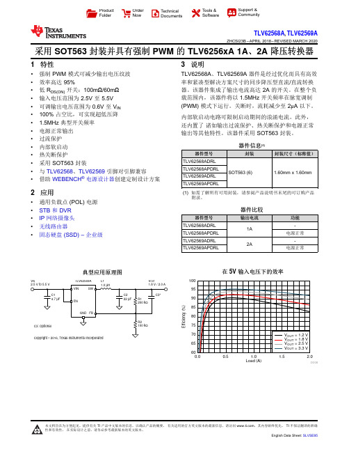
Load (A)E f f i c i e n c y (%)0.00.51.0 1.52.06065707580859095100D008V INV OUTL1TLV62569AProduct Folder Order Now Technical Documents Tools &SoftwareSupport &CommunityTLV62568A ,TLV62569AZHCSI23B –APRIL 2018–REVISED MARCH 2020采用SOT563封装并具有强制PWM 的TLV6256xA 1A 、2A 降压转换器1特性•强制PWM 模式可减少输出电压纹波•效率高达95%•低R DS(ON)开关:100m Ω/60m Ω•输入电压范围为2.5V 至5.5V •可调输出电压范围为0.6V 至V IN •100%占空比,可实现超低压降• 1.5MHz 典型开关频率•电源正常输出•过流保护•内部软启动•热关断保护•采用SOT563封装•与TLV62568、TLV62569引脚对引脚兼容•借助WEBENCH ®电源设计器创建定制设计方案2应用•通用负载点(POL)电源•STB 和DVR •IP 网络摄像头•无线路由器•固态硬盘(SSD)–企业级3说明TLV62568A 、TLV62569A 器件是经过优化而具有高效率和紧凑型解决方案尺寸的同步降压型直流/直流转换器。
该器件集成了输出电流高达2A 的开关。
在整个负载范围内,该器件将以1.5MHz 开关频率在脉宽调制(PWM)模式下运行。
关断时,流耗减少至2μA 以下。
内部软启动电路可限制启动期间的浪涌电流。
此外,还内置了诸如输出过流保护、热关断保护和电源正常输出等其他特性。
该器件采用SOT563封装。
器件信息(1)器件型号封装封装尺寸(标称值)TLV62568ADRL SOT563(6)1.60mm x 1.60mmTLV62568APDRL TLV62569ADRL TLV62569APDRL(1)如需了解所有可用封装,请参阅产品说明书末尾的可订购产品附录。
GR-326-CORE 中文

内容前言1.介绍1.1 目的和范围1.2 所面向的读者1.3 本文档的结构和使用1.4 相对于GR-326-CORE的变化1.5 要求术语1.6 要求标记约定1.6.1 要求和相关目标的编号1.6.2 要求,特殊条件下的要求,客观目标点辨认2. 通用信息2.1 描述2.2 连接器的应用3. 一般要求3.1 文档3.2 保证和运输3.3 设计特征3.3.1 材料3.3.2 可清洗性3.4 兼容性3.4.1 推拉(插拔)型连接器的扣接兼容性3.5 产品标记和包装3.5.1 方向定位3.5.2 特殊光纤3.6 安全4. 连接器测试和标准4.1 测试样品4.1.1 定义4.1.2 总体4.2 标准4.2.1 光学性能标准回顾4.2.2 修正和条件4.2.2.1 测量误差4.2.2.2 跳接线组装测量4.2.2.3 反射损失增长标准的适用性4.2.2.4 反射损失标准的适用性4.2.2.5 不符合性的处理4.2.3 损坏标准4.3 清洗流程4.3.1 清洗流程A4.3.2 清洗流程B4.4 标准描述4.4.1 新产品性能4.4.2 温度,湿度,冷凝测试4.4.2.1 高温老化测试4.4.2.2 高温循环测试4.4.2.3 高湿老化测试4.4.2.4 高湿/冷凝循环测试4.4.2.5 烘干步骤4.4.2.6 冷凝后高温循环测试4.4.3 机械测试4.4.3.1 振动测试4.4.3.2 弯曲测试4.4.3.3 扭曲测试4.4.3.4 耐力测试4.4.3.4 施加张力时的传输性能4.4.3.6 平衡张力负载4.4.3.7 碰撞测试4.4.3.8 持久性4.4.3.9 测试标准的最后4.4.4 材料和环境测试4.4.4.1 灰尘测试4.4.4.2 黏着性测试4.4.4.3 空气中的污染物4.4.4.4 盐水喷雾4.4.4.5 浸渍/侵蚀测试4.4.4.6 地下水侵蚀4.4.5 几何要求4.4.5.1 无角度PC连接器的Ferrule端面几何形状4.4.5.2 APC连接器Ferrule端面几何形状4.4.5.3 端面几何形状测量区域4.4.6 连接器安装5. 产品测试设备5.1 试验条件5.2 光学测量5.2.1 传输测量所需设备5.2.1.1 用一种传输测量设备进行损失测量5.2.1.2 用一种传输测量设备进行反射损失测量5.2.2 OTDR 测量设备5.2.2.1 用OTDR测量损失5.2.2.2 用OTDR测量反射损失5.3 产品测试设备5.3.1 环境测试5.3.2 振动测试5.3.3 跳线张力测试治具5.3.4 持久性测试5.3.5 碰撞测试5.3.6 黏着性测试5.3.7 灰尘测试5.3.8 地下水侵蚀测试6. 使用寿命测试6.1 使用寿命测试6.2 新产品测量6.3 张力测试7. 可靠性测试7.1 可靠性测试描述7.2 可靠性测试样品7.2.1 样品种类7.2.2 样本尺寸7.3 可靠性测试所使用的标准8. 可靠性保证项目8.1 可靠性测试8.2 制造和过程控制8.2.1材料和元件8.2.1.1 质量水平8.2.1.2 测量和元件要求8.2.1.2.1 供应商资格认证8.2.1.2.2 部件验证8.2.1.2.3 Epoxies(环氧树脂胶)验证8.2.1.2.4 原材料说明8.2.1.2.5 原材料的可接受性判定8.2.1.2.6 可靠性控制8.2.2.1.2.7 反馈和改良措施8.2.2 物理设计8.2.2.1 不同金属的接触8.2.2.2 易燃性8.2.3 制造和组装8.2.3.1 培训8.2.3.2 产品文档8.2.3.3 产品检查8.2.3.3.1 对不合格材料的隔离8.2.3.3.2 产品的存储和处理8.2.3.4 产品组装8.2.3.5 产品的可追溯性8.2.3.6 顾客抱怨8.2.3.7 现场试验8.2.3.8 统计过程控制和质量数据8.2.4 制造商测试8.2.4.3.2 连接器所用之转换器8.2.4.3.3 测试部件的替换8.2.4.4 标定8.2.4.5 产品合格性测试8.2.4.5.1 最初合格性的重复8.2.4.5.2 周期性合格性测试方案8.2.4.1 测试文档8.2.4.2 在线测试8.2.4.3 完成品测试8.2.4.3.1 测试数据8.2.4.3.2 适配器8.2.4.3.3 测试零件的替换8.2.4.4 校准8.2.4.5 产品质量测试8.2.4.5.1 最初测试的重复8.2.4.5.2 周期性测试计划前言简而言之,此前言包括Telcordia GR标准程序和该文件的重要信息。
irelay_60综合保护测控装置用户说明书 ()

iRelay 60综合保护测控装置用户说明书危险和警告本设备只能由专业人士进行安装,对于因不遵守本手册的说明所引起的故障,厂家将不承担任何责任。
重要提示感谢您使用深圳市中电电力技术股份有限公司的产品。
为了安全、正确、高效地使用本装置,请您务必注意以下重要提示:1) 本说明书仅适用于iRelay 60综合保护测控装置。
2) 请仔细阅读本说明书,并按照说明书的说明设置、测试和操作。
如有随机资料,请以随机资料为准。
3) 为防止装置损坏,严禁带电插拔装置各插件、触摸印制电路板上的芯片和器件。
4) 请使用合格的测试仪器和设备对装置进行试验和检测。
5) 装置如出现异常,请及时与本公司售后技术服务(400-8860-418)联系。
6) 本装置的设置缺省密码是:0000。
本说明书版权属深圳市中电电力技术股份有限公司所有,未经书面许可,不得复制,传播或使用本文件及其内容,违犯者将要对损坏负责。
深圳市中电电力技术股份有限公司保留所有版权。
我们已经检查了本手册关于描述硬件和软件保持一致的内容。
由于不可能完全消除差错,所以我们不能保证完全的一致。
本手册中的数据将定期审核,并在新一版的文件中做必要的修改,欢迎提出修改建议。
以后版本中的变动不再另行通知。
目录1 装置简介 (1)1.1 概述 (1)1.2 产品特点 (1)1.3 基本功能 (2)2 技术指标 (3)2.1 工作环境条件 (3)2.2 额定参数 (3)2.3 准确度 (3)2.4 遥信分辨率 (4)2.5 过载能力 (4)2.6 继电器输出 (4)2.7 开关量输入 (4)2.8 电气绝缘性能 (4)2.9 机械性能 (5)2.10 电磁兼容性能 (5)3 功能说明 (6)3.1 保护功能 (6)3.1.1 辅助元件 (6)3.1.2 大电流闭锁保护 (9)3.1.3 相电流充电保护 (10)3.1.4 相电流加速保护 (10)3.1.5 开入加速相电流保护 (11)3.1.6 速断保护 (11)3.1.7 限时速断保护 (12)3.1.8 过流保护 (13)3.1.9 过负荷保护 (14)3.1.10 反时限过流保护 (14)3.1.11 电压速断保护 (15)3.1.12 电压限时速断保护 (16)3.1.13 IN充电保护 (17)3.1.14 IN加速保护 (17)3.1.15 IN过流保护 (18)3.1.16 IN反时限过流保护 (19)3.1.17 I0充电保护 (19)3.1.18 I0加速保护 (20)3.1.19 I0过流保护 (20)3.1.20 I0反时限过流保护 (21)3.1.21 负序过流保护 (21)3.1.22 负序反时限保护 (22)3.1.23 电流不平衡保护 (22)3.1.24 过电压保护 (22)3.1.25 低电压保护 (23)3.1.28 VX低压保护 (25)3.1.29 高周保护 (25)3.1.30 低周保护 (26)3.1.31 功率保护 (26)3.1.32 同期检查 (27)3.1.33 重合闸功能 (29)3.1.34 绝缘监视 (31)3.1.35 起动间隔保护 (31)3.1.36 TV断线监视 (32)3.1.37 TA监视 (32)3.1.38 控制回路监视 (32)3.1.39 有效值过压保护 (33)3.1.40 有效值过流保护 (33)3.1.41 电动机运行状态判断 (34)3.1.42 起动时间过长保护 (35)3.1.43 过热保护 (35)3.1.44 tE时间保护 (36)3.1.45 堵转保护 (36)3.1.46 负荷丢失保护 (37)3.1.47 再起动功能 (37)3.1.48 起动次数保护 (38)3.1.49 开关量保护 (39)3.2 测量功能 (39)3.2.1 一次值 (39)3.2.2 二次值 (39)3.2.3 计量数据 (40)3.3 遥信功能 (40)3.4 控制功能 (40)3.5 通信功能 (40)3.6 记录功能 (41)3.6.1 事件记录 (41)3.6.2 故障录波记录 (42)3.6.3 波形瞬态捕捉功能 (42)3.6.4 起动报告功能 (43)3.7 对时功能 (43)4 操作使用说明 (47)4.1 装置前面板 (47)4.2 按键操作 (47)4.3 信号指示灯 (48)4.4 装置上电 (48)4.5 默认显示界面 (48)4.6 事件报告显示 (49)4.7 菜单说明 (49)4.7.3 定值设置 (53)4.7.4 报告管理 (59)4.7.5 装置维护 (61)4.7.6 装置调试 (62)4.7.7 定值清单 (62)5 安装调试说明 (74)5.1 安装 (74)5.1.1 装置安装图 (74)5.1.2 背板端子布置 (75)5.2 时钟电池 (78)5.3 通电试验 (78)5.4 投运前调试 (78)5.5 装置故障分析 (80)6 接线原理图 (82)6.1 装置接线示意图 (82)7 售后服务承诺 (87)7.1 装置升级 (87)7.2 质保范围 (87)7.3 售后联系方式 (87)1 装置简介1.1 概述iRelay 60是深圳市中电电力技术股份有限公司(以下简称中电技术)精心开发的,适用于中高压电压等级的新一代智能化微机综合保护测控装置。
RFC3261中文版
SIP: Session Initiation Protocol目录1、SIP协议介绍92、SIP协议功能概况103、术语124、实施概览125、协议的结构226、协议的定义247、SIP消息:337.1 请求347.2应答357.3 头域367.3.1 头域格式。
367.3.2 头域分类。
397.3.3 缩写格式407.4包体407.4.1 消息正文类型(MessageBodyType)407.4.2 消息体长度417.5 分帧的SIP消息(Framing SIP Messages)418 一般用户代理行为418.1 UAC特性428.1.1 产生一个请求428.1.1.1 Request-URI438.1.1.2 TO438.1.1.3 From448.1.1.4 Call-ID458.1.1.5 Cseq468.1.1.6 Max-Forwards468.1.1.7 Via478.1.1.8 Contact488.1.1.9 Supported 和 Require488.1.1.10 附加信息部分498.1.2 发送一个请求498.1.3 处理应答508.1.3.1: transaction 层的错误508.1.3.2 未知的应答518.1.3.3 Vias518.1.3.4 处理3xx应答518.1.3.5 处理4xx应答538.2 UAS特性548.2.1 方法判定558.2.2 XX判断558.2.2.1 TO 和Request-URI558.2.2.2 合并的请求568.2.2.3 Require568.2.3 内容处理578.2.4 应用扩展588.2.5 处理请求588.2.6 产生应答598.2.6.1 发送一个临时应答598.2.6.2 XX和Tags598.2.7 无状态UAS行为608.3 重定向服务器619 取消一个请求(Cancel)639.1 客户行为(Client Behavior)639.2 服务端行为(Server Behavior)6510 注册(Registrations)6610.1 概览6610.2 构造一个REGISTER请求6710.2.1 增加绑定7010.2.1.1 设置Contact地址的过期参数7110.2.2 删除绑定7110.2.3 访问绑定7210.2.4 刷新绑定7210.2.5 设置内部时钟7310.2.6 寻找注册服务器7310.2.7 传送一个请求7310.2.8 错误响应7410.3 处理REGISTER请求7411 查询能力7711.1 构造OPTIONS请求7811.2 处理OPTIONS请求7912 对话(Dialog)8112.1 创建一个对话8212.1.1 UAS行为8312.1.2 UAC行为8412.2 对话中的请求8512.2.1 UAC行为8612.1.1.1 产生请求8612.2.1.2 处理应答8812.2.2 UAS行为8912.3 终止对话9013 初始化一个会话9013.1 概览9013.2 UAC处理9113.2.1 创建一个初始化的INVITE9113.2.2处理INVITE应答9413.2.2.1 1xx应答9413.2.2.2 3xx应答9513.2.2.3 4xx,5xx,6xx应答9513.2.2.4 2xx 应答9513.3 UAS处理9713.3.1 处理INVITE9713.3.1.1 提示进度9813.3.1.2 INVITE请求转发9913.3.1.3 INVITE请求的拒绝9913.3.1.4 接受INVITE请求9914 更改已经存在的会话10014.1 UAC行为10114.2 UAS行为10315 结束一个会话10415.1 使用BYE请求终止一个会话10615.1.1 UAC行为10615.1.2 UAS行为10616 proxy行为10716.1 概述10716.2 有状态的proxy10816.3 验证请求11016.4 路由信息预处理11216.5 确定请求的目的11316.6 请求转发11516.7 应答的处理12516.8 处理定时器C13416.9 处理通讯层的错误13416.10 CANCEL处理13516.11 无状态的proxy13616.12 Proxy Route处理的总结13816.12.1例子13916.12.1.1 基本SIP四边形13916.12.1.2 穿越一个严格路由proxy141 17事务14417.1 客户端事务14717.1.1 INVITE客户事务14717.1.1.1 INVITE事务概述14717.1.1.2 正式的描述14817.1.1.3 构造ACK请求15217.1.2 非INVITE客户端事务15417.1.2.2 正式的描述15417.1.3 客户端事务匹配应答15617.1.4 处理通讯错误15617.2 服务端事务15817.2.1 INVITE服务端事务15817.2.2 非INVITE服务端事务16117.2.3 为服务端事务匹配请求。
- 1、下载文档前请自行甄别文档内容的完整性,平台不提供额外的编辑、内容补充、找答案等附加服务。
- 2、"仅部分预览"的文档,不可在线预览部分如存在完整性等问题,可反馈申请退款(可完整预览的文档不适用该条件!)。
- 3、如文档侵犯您的权益,请联系客服反馈,我们会尽快为您处理(人工客服工作时间:9:00-18:30)。
Applications
․Audio equipment ․Instrument panels ․Digital read out display
Device Selection Guide
Chip Material GaAsP/GaP Emitted Color Red Gray Face Color
Descriptions
․The ELLS-326series is a large 7.00mm (0.28")high seven segment display designed for viewing distances up to 7 meters. ․These displays provide excellent reliability in bright ambient light. ․These devices are made with white segments and gray surface.
元器件交易网
Technical Data Sheet 0. 28" Single Digit Leadframe Displays
ELLS-326RWA
Features
․Industrial standard size. ․Low power consumption. ․Categorized for luminous intensity. ․Pb free
Everlight Electronics Co., Ltd. Device No.: CDFS-326-003
Rev. 1
Page: 1 of 1
元器件交易网
ELLS-326RWA
Package Dimensions
․All dimensions are in millimeters,tolerance is 0.25mm unless otherwise noted. ․Above specification may be changed without notice. Supplier will reserve authority on material change for above specification
*2
Symbol IF IFP Topr Tstg Tsol Pd VR
Rating 25 160 -40 ~ +85 -40 ~ +100 260 60 5
Units mA mA ℃ ℃ ℃ mW V
Notes: *1:IFP Conditions--Pulse Width≦10msec and Duty≦1/10. *2:Soldering time≦5 seconds.
Everlight Electronics Co., Ltd. Device No.: CDFS-326-003
Rev. 1
Page: 3 of 3
元器件交易网
ELLS-326RWA
Typical Electro-Optical Characteristics Curves
Absolute Maximum Ratings (Ta=25℃)
Parameter Forward Current Pulse Forward Current*1 Operating Temperature Storage Temperature Soldering Temperature Power Dissipation Reverse Voltage
Parameter Forward Voltage Reverse Current Luminous Per segment Intensity Per decimal point Peak Wavelenght Dominant Wavelenght Spectrum Radiation Bandwidth Symbol VF IR Condition IF=20mA VR=5V Min. --0.18 IV IF=10mA -λp λd △λ IF=20mA IF=20mA IF=20mA ----632 624 20 ----nm nm nm Typ. 2.0 -0.90 Max. ---10 -mcd Units V μA
Chromaticity Coordinates Specifications for Bin Grading(Unit:mcd)
Rank E F G Min. 0.18 0.28 0.45 Max. 0.36 0.56 0.90 Rank H I -Min. 0.7 1.10 -Max. 1.40 2.20 --
Everlight Electronics Co., Ltd. Device No.: CDFS-326-003
Rev. 1
Page: 2 of 2
元器件交易网
ELLS-326RWA
Electro-Optical Characteristics (Ta=25℃)
Everlight Electronics Co., Ltd. Device No.: CDFS-326-003
Rev. 1
Page: 4 of 4