Two-Photon Emission from Semiconductors
胆甾相液晶激光器研究进展

胆甾相液晶激光器研究进展张世超;黄玉华;王辉【摘要】Cholesteric liquid crystal lasers have been extensively studied but barely studied in our country.The periodic helical structure and selective reflection property of cholesteric liquid crystal were introduced.The principle and research progress of cholestenc liquid crystal based lasers and its potential applications were reviewed to provide some reference for the specialists in our country.%近年来国外学者对胆甾相液晶激光进行了大量研究,而国内在这方面研究甚少.介绍了胆甾相液晶周期性螺旋结构及其选择性反射特性,以及胆甾相液晶激光的工作原理,总结了胆甾相液晶激光的发展现状及其潜在的应用前景,以期为国内液晶研究的同行提供一点参考.【期刊名称】《激光技术》【年(卷),期】2011(035)004【总页数】4页(P514-517)【关键词】激光器;胆甾相液晶;液晶激光器;光子带隙【作者】张世超;黄玉华;王辉【作者单位】浙江师范大学,信息光学研究所,金华,321004;浙江师范大学,信息光学研究所,金华,321004;浙江师范大学,信息光学研究所,金华,321004【正文语种】中文【中图分类】O43;TN248引言光子晶体是一种介电常数呈周期性变化的介电质,会形成光子禁带和导带,光子在导带里可以顺利传播,在光子禁带内则会被禁止。
这一特点使得光子晶体可以应用于很多领域,尤其在集成光学具有巨大的应用前景,因此引起了广泛的研究兴趣。
自动往返电动小汽车(毕业设计)

一. 毕业实践任务书无锡职业技术学院毕业实践任务书课题名称:自动往返电动小汽车指导教师:XXXXXXX 职称:讲师指导教师:职称:专业名称:XXXXXXXX 班组:XXXXXX学生姓名:XXXXXXX 学号:05一. 课题需要完成的任务:设计并制作一个能自动往返于起跑线与终点线间的小汽车。
允许用玩具汽车改装,但不能用人工遥控(包括有线和无线遥控)。
图1跑道顶视图跑道宽度0.5m,表面贴有白纸,两侧有挡板,挡板与地面垂直,其高度不低于20cm。
在跑道的B、C、D、E、F、G各点处画有2cm宽的黑线,各段的长度如图1所示。
设计要求1、车辆从起跑线出发(出发前,车体不得超出起跑线),到达终点线后停留10秒,然后自动返回起跑线(允许倒车返回)。
往返一次的时间应力求最短(从合上汽车电源开关开始计时)。
2. 达终点线和返回起跑线时,停车位置离起跑线和终点线偏差应最小(以车辆中心点与终点线或起跑线中心线之间距离作为偏差的测量值)。
D~E间为限速区,车辆往返均要求以低速通过,通过时间不得少于8秒,但不允许在限速区内停车。
二. 课题计划:2006.3.3~2006.3.6 熟悉课题,可行性方案分析及方案论述。
2006.3.7~2006.3.19 查阅资料,设计各部分硬件。
2006.3.19~2006.4.10 画原理图,印刷线路板。
2006.4.10~2006.4.20 编写程序验证部分硬件。
2006.4.21~2006.4.25 写出毕业论文。
计划答辩时间:4.21-4.28XXXXX 系(部、分院)2006年02年18日二.外文翻译VIDEOCASSETTEBefore the videocassette recorder there was the movie projector and screen. Perhaps you remember your fifth-grade teacher pulling down a screen—or Dad hanging a sheet on the wall, ready to show visiting friends the enthralling account of your summer vacation at the shore. Just as the film got started, the projector bulb often blew out.Those days did have one advantage, though: the screen was light, paper-thin and could be rolled into a portable tube. Compare that with bulky television and computer screens, and the projector screen invokes more than just nostalgia. Could yesterday's convenience be married to today's technology?The answer is yes, thanks to organic light-emitting materials that promise to make electronic viewing more convenient and ubiquitous. Used in displays, the organic materials are brighter, consume less energy and are easier to manufacture (thus potentially cheaper) than current options based on liquid crystals. Because organic light-emitting diodes (OLEDs) emit light, they consume significantly less power, especially in small sizes, than common liquid-crystal displays (LCDs), which require backlighting. OLEDs also offer several exciting advantages over common LEDs: the materials do not need to be crystalline (that is, composed of a precisely repeating pattern of planes of atoms), so they are easier to make; they are applied in thin layers for a slimmer profile; and different materials (for different colors) can be patterned on a given substrate to make high-resolution images. The substrates may be inexpensive glass or flexible plastic or even metal foil.In the coming years, large-screen televisions and computer monitors could roll up for storage. A soldier might unfurl a sheet of plastic showing a real-time situation map. Smaller displays could be wrapped around a person's forearm or incorporated into clothing. Used in lighting fixtures, the panels could curl around an architectural column or lie almost wallpaperlike against a wall or ceiling.LEDs currently have longer lifetimes than organic emitters, and itwill be tough to beat the widespread LED for use in indicator lamps. But OLEDs are already demonstrating their potential for displays. Their screens put out more than 100 candelas per square meter (about the luminance of a notebook screen) and last tens of thousands of hours (several years of regular use) before they dim to half their original radiance.Close to 100 companies are developing applications for the technology, focusing on small, low-power displays [see box on page 80]. Initial products include a nonflexible 2.2-inch (diagonal) display for digital cameras and cellular phones made jointly by Kodak and Sanyo, introduced in 2002, and a 15-inch prototype computer monitor produced by the same collaborative venture. The global market for organic display devices was about $219 million in 2003 and is projected to jump to $3.1 billion by 2009, according to Kimberly Allen of iSuppli/Stanford Resources, a market-research firm specializing in displays.一、What LED to OLEDCRYSTALLINE semiconductors—the forerunners of OLEDs—trace their roots back to the development of the transistor in 1947, and visible-light LEDs were invented in 1962 by Nick Holonyak, Jr. They were first used commercially as tiny sources of red light in calculators and watches and soon after also appeared as durable indicator lights of red, green or yellow. (When suitably constructed, LEDs form lasers, which have spawned the optical-fiber revolution, as well as optical data storage on compact discs and digital video discs.) Since the advent of the blue LED in the 1990s [see “Blue Chip,” by Glenn Zorpette; Scientific American, August 2000], full-color, large-screen television displays made from hundreds of thousands of LED chips have appeared in spectacular fashion on skyscrapers and in arenas [see “In Pursuit of the Ultimate Lamp,” by M. George Crawford, Nick Holonyak, Jr., and Frederick A. Kish, Jr.; Scientific American, February 2001]. Yet the smaller sizes used in devices such as PDAs (personal digital assistants) and laptops are not as practical.LEDs and OLEDs are made from layers of semiconductors—materials whose electrical performance is midway between an excellent conductorsuch as copper and an insulator such as rubber. Semiconducting materials, such as silicon, have a small energy gap between electrons that are bound and those that are free to move around and conduct electricity. Given sufficient energy in the form of an applied voltage, electrons can “jump” the gap a nd begin moving, constituting an electrical charge. A semiconductor can be made conductive by doping it; if the atoms added to a layer have a smaller number of electrons than the atoms they replace, electrons have effectively been removed, leaving positively charged “holes” and making the material “p-type.” Alternatively, a layer that is doped so that it has an excess of negatively charged electrons becomes “n-type” [see box on opposite page]. When an electron is added to a p-type material, it may encounter a hole and drop into the lower band, giving up an amount of energy (equal to the energy gap) as a photon of light. The wavelength depends on the energy gap of the emitting material.For the production of visible light, organic materials should have an energy gap between their lower and higher conduction bands in a relatively small range, about two to three electron volts. (One electron volt is defined as the kinetic energy gained by an electron when it is accelerated by a potential difference of one volt. A photon with one electron volt of energy corresponds to the infrared wavelength of 1,240 nanometers, and a photon of two electron volts has a wavelength half as much—620 nanometers—a reddish color.)二、A Surprising GlowORGANIC semiconductors are formed as aggregates of molecules that are, in the technologies being pursued, amorphous—a solid material, but one that is noncrystalline and without a definite order. There are two general types of organic light emitters, distinguished by “small” and “large” molecule sizes. The first practical p-n-type organic LED, based on small molecules, was invented in 1987 by Ching W. Tang and Steven A. Van Slyke of Eastman Kodak, after Tang noticed a surprising green glow coming from an organic solar cell he was working on. The duo recognized that by using two organic materials, one a good conductor of holes and the other a good conductor of electrons, they could ensure that photon emission would take place near the contact area, or junction, of the two materials, as in acrystalline LED. They also needed a material that held its electrons tightly, meaning that it would be easy to inject holes. For the light to escape, one of the contacts must be transparent, and the scientists benefited from the fortunate fact that the most widely used transparent conducting material, indium tin oxide, bound its electrons suitably for p-type contact material.The structure they came up with has not changed much over the years and is often called “Kodak-type,” because Kodak had the basic patent [see box on opposite page]. Beginning with a glass substrate, different materials are deposited layer by layer. This process is accomplished by evaporating the constituent materials and letting them condense on the substrate. The total thickness of the organic layers is only 100 to 150 nanometers, much thinner than that of a conventional LED (which is at least microns in thickness) and less than 1 percent of the thickness of a human hair. Because the molecules of the materials used are relatively lightweight—even lighter than a small protein—the Kodak-type OLEDs are referred to as “small molecule” OLEDs.After their initial insight, Tang and Van Slyke tinkered with the design to increase efficiency. They added a small amount of the fluorescent dye coumarin to the emitter material tris (8-hydroxy-quinoline) aluminum. The energy released by the recombination of holes and electrons was transferred to the dye, which emitted light with greatly increased efficiency. Deposition of additional thin layers of indium tin oxide and other compounds next to the electrodes altered the interaction of the thicker layers and also improved the efficiency of the injection of holes and electrons, thereby further upping the overall power efficiency of the fluorescent OLED.Organic LEDs of this small-molecule type are used to make red, green and blue light, with green light having the highest efficiency. Such green-emitting OLEDs can exhibit luminous efficiencies of 10 to 15 candelas per ampere—about as efficient as commercial LEDs today—and seven to 10 lumens per watt, values that are comparable to those for common incandescent lamps.录像机在卡匣式录像机出来之前,我们用的是电影放映机与屏幕。
7. Emission and Absorption

光电英语词汇汇总
光电英语词汇汇总photographic reconnaissance 照相侦察photographic recorder 摄影记录器,录相器photographic refractor 天体折射照相仪photographic reproduction 照相复制法photographic sensitometer 感光度测定仪photographic snesitivity 感光度photographic sound recorder 光录声机photographic standard irradiance 照相标准辐照度photographic tansmission density 照相透光密度photographic zenith tube 照光天顶管photography 照相术,摄影术photogravure 照相凹板印刷photogroduct 光化产品photogun 光电子枪photohalide 感光卤化物photohead 光电传感头photoheliograph 太阳照相机photoheliography 太阳照相术photohole 光穴photohyalography 光照蚀刻术photoimpact (1)光冲量(2)光控脉冲photoinactivation 光纯化作用photoinduced 光致的,光感生的photoinduced strain 光致应变photoinduction 光诱导,光感生photointaglio 照相板,影印版photointerpreter 相片判读装置photoionization 光致电离photoionization detector 光电离检测器photoionization threshold 光致电离阈photoisomer 光致同分异体photoisomerisom 光致同分异构photojunction cell 光电二极管photojunction diode 光电二极管photoklystron 光电速调管photolabile 对光不稳的photolayer 光敏层photolesn chromatism 摄影透镜色差photoline 光线photolithgraphic 光刻法的photolithography 光蚀刻微影; 光刻法; 平印照相制板photolocking 光锁定photology 光学photoluminescence 光致发光photoluminescence efficiency curve 光致发光效率曲线photolysis 光解作用photolyte 光解质photolytic 光解的photom 光度学photomacrogaph 宏观照片photomagnetic 光磁的photomagnetic effect 光磁效应photomagnetoelectric 光磁电的photomagnetoelectric effect 光磁电效应photomap 空中摄影地图photomask 光掩模photomask materials 光罩材料photomation 自体摄印相机photomatrices 光矩阵photomechanical 光学机械的photometallic etching 光金属蚀刻photometallurgical microscope 金相摄影显微镜photometeor 发光陨星photometer 光度计photometer bench 光度计座photometer head 光度计头photometers 光度计photometric 光度的photometric brightness 光亮度photometric brightness scale 光亮度标photometric calibration 光度校正photometric calibration data files 光度校准数据文件photometric computer 测光计算机photometric head 光度头photometric integrating sphere 光度积分球photometric method 光度测定法photometric paradox 光度佯谬photometric parallax 光度视差photometric period 光度周期photometric quality 光度质量photometric quantity 光度值,光度量photometric receiver 光度计photometric relationship 光度关系photometric repartition 光度分布photometric scale 光度标photometric standard 光度标准photometric standard lamp 光度标准灯photometric sterance 光辐通量photometric term 光度学术photometric test 光度检查photometric test plate 光度试验板photometric transfer function 光度传逊函数photometric units 光度学单位photometric wedge 测光楔photometry 光度学,光度测量术photomicrograph (1)显微照置(2)显微照片photomicrographic apparatus 显微照相装置photomicrographic tungsten arc lamp 显微照相钨弧光灯photomicrography 显微照相术photomicrometer 显微光度计photomicroscope 照相显微镜photomixer 光混频器photomixer diode 光混频二极管photomixing 光混频photomixing device 光源频器photomixing technique 光混频技术photomodulator 光调制器photomontage (1)光片剪辑(2)合成照片photomosaic 感光镶嵌幕photomotion 光激活动photomultiplier 光电倍增管photomultipliers 光电子增倍管(PMT)photomuon 光μ介子photon 光子photon absorption 光子吸收photon activated switch 光子起动开关photon amplification 光子放大photon annihilation 光子湮没photon avalanche 光子雪崩photon beam 光子束photon bombardment 光子轰系photon bunching 光子聚束photon capture 光子俘获photon counter 光子计数器photon counting spectrophotometer 光子计数分度计photon density 光子密度photon detector 光子探测器photon drag detector 光子牵引探测器photon drag photodetector 光子牵引光探测器photon effect 光子效应photon emission 光子发射photon excited atom 光子激发原子photon exitance 光子出photon fluctuation 光子起伏,光子波动photon flux 光子通量photon intensity 光子强度photon irradiance 光子辐射度photon liberation 光子逸出photon lifetime 光子寿命photon limited sensitivity 光子限灵敏度photon nosie 光子噪声photon radiance 光子辐射强度,光子辐射率photon statistics 光子统计学,光子流统计分布photon steradiance 光子辐射强度photon stream 光子流photon structure 光子结构photon-generated carrier 光生载流子photon-induced 光子感生的photon-induxed action 光子感生作用photonegative effect 负光电效应photonephelometer 光电浊度计photoneutron 光激中子photoneutron emission 光激中子发射photonic band structures 光子能带结构photonic band-gap (PBG) system 光能隙系统photonic bandgap 光子能隙photonic crystal 光子晶体photonic crystal fiber 光子晶体光纤photonic crystals 光子晶体Photonics 光电photonoise limit 光子噪声限photontransition 光子跃迁photonuclear disintegration 光致核蜕变photonuclear excitation 光核激发photooxidation 感光氧化用,光致氧化作用photooxygenation 光致氧化photooxygenation actinometer 光致氧化感光计photopeak 光巅,光峰photopen recorder 光笔记录器photoperiod 光周期photoperspectograph 摄影透视仪photophase 光相位photophobia 畏光症photophone 光电话,传真电话photophoresis 光致漂移photophysics 光子物理学photopia 光适应photopic eye 适光眼photopic range 适光范围photopic vison 亮视觉,白画视觉photoplane 摄影飞机photoplastic effect 光塑性效雁photoplastic material 光塑材料photoplastic recording 感光塑料记录photoplate 照相底片photopolymer 光聚合物photopolymer holography 光聚合物全息术photopolymerization 光聚作用photopositive 照相正片photopredissociation 光致预离解photoprigment 感光色素photoprint 影印,照页复制photoprocess 光学处理,光学加工photoproduction 光致作用,光生photoproducton cross-section 光致作用截面photoptometer 光敏计,光觉计photoptometry 辨光测验术photoradar 光雷达photoradiogram 光电传真电报photoransmitter 照片传真发器photoreaction 光致反应photoreader 光电读出器photoreading 光读婺photoreceiver 照片传真接器,光接收器photoreceptor 光感受器photorecombination laser 光复合激光器photoreconnaissance 摄影侦察photoreconversion 光致再转换photorecorder 摄影记录器,自动照明记录器photorectifier 光电检波器photoreduce 照相缩小photoreduction (1)光致还原(2)照相缩版photorefraction 光折射photorefractive 光致折变的photorefractive effect 光折射效应photorelay 光继电器photorepeater 复印机photoresist optics exposure 光电导曝光photoresistance 光敏电photoresistor 光敏电阻photoresistor-cell relay 光敏元件继电器photoresponse 光响应photoresponsive retina 光响应视网膜photoresponsive tube 光响应管photorproton 光质子photoscanning 光扫描photoscope 透视镜photosensing units 光感测元件photosensitiser 感光剂,光敏剂photosensitive 光感的,感光的photosensitive area 光敏区,光敏面积photosensitive device 光敏器件photosensitive film 光敏膜photosensitive glass 光敏玻璃photosensitive layer 光敏层photosensitive material 感光材料photosensitive medium 光敏媒质photosensitiveness 光敏性,光敏度photosensitivity 光敏性,感光性,感光灵敏度photosensitization 光敏作用photosensitizer 光敏剂photosensor 光敏器件photoseparation 光分离photoset 照相版排photosignal 光信号photosource 光源photosphere 光球层photospot 聚光photostability 耐光性photostable 不感光的,耐光的photostar 发光星体photosterograph 立体测图仪photostimulaton 光剌激photostudio (1)照相馆(2)摄影棚photosurface 光敏面photosurface spectral response 光敏面光谱响应photoswitch 光开关photosynthesis 光合作用phototaxis 趋光性phototelegram 传真电报phototelegraph 传真电报phototelegraphy 传真电报术phototelephone 传真电报机phototelephony 传真电话术phototelescope 照相望远镜phototherapeutics 光线治疗学phototherapy 光线疗法photothermionic image converter 光热离子变相管phototimer (1)曝光计(2)摄影计时器(3)延时光控继电器phototiming 光同调步phototransistor 光电晶体管,光敏三极管phototransistors 光电晶体phototransmutation 感光蜕变phototriode 光电三极phototroller 光控电管phototron 矩阵光电管phototrop 光色互变phototropic 向光的phototropic vision 摄影仪phototropism (1)趋光性,向光性(2)光色互变现象phototube 光电管phototubes 光电管phototype 珂罗版phototypesetter 照相排字机photounit 光电件photovalue 光阀photovaoltaic 光生伏打的photovisual objective 拟视照相物镜photovisula achromatism 光化视觉消色差性photovolt desitometer 光电密度计photovoltage 光电压photovoltaic 光生伏打photovoltaic cell 光生伏打电池photovoltaic converter 光伏变换器,光电能量变换器photovoltaic effect 光生伏打效应photovoltaic infrared detector 光伏红外探测器photox cell 氧化亚铜光电元件photoxide 光氧化物photozincograph 照相锌版photsyntometer 光合计phrolysis 高温分解,热解phromagnetic 热磁的phromagnetic detection 热磁探测phse-modulated signals 调相信号phse-modulated waves 调相波phthalocyanin 屻花悄phtoochromatic filter 光致变色滤光器physi-optics 物理光学physical absorption 物理吸附Physical chemistry 物理化学physical constraint 物理约束physical development 物理显影physical entropy 物理熵physical interpretation 物理解释physical optics 物理光学physical photometer 物理光度计physical photometry 物理光度测量学physical quantity 物理量physical thickness 物理厚度physics 物理学physiological 生理的physiological blur 生理模糊斑physiological model 生理模型physiological optics 生理光学physiological photometer 生理光度计physiology 生理学physioptial 物理光学的pic (1)图片,照片(2)图画,图像pic-up device 摄像装置pick-off diode 截止二极管pick-off gear 可互换齿轮pick-up (1)拾波,拾声(2)拾波器(3)拾声器(4)传感器(5)电视摄像管pick-up camera 摄像机pick-up head lenses 光碟机读取头透镜pick-up system 摄像系械pick-up tube 摄像管pickoff (1)传感器,探测器(2)截止(3)拾取pickoff couple 截止耦合器pickoff unit (1)接收器(2)截止器piclear unit 图像清除器picling (1)酸浸(2)浸渍picnometer (1)比重瓶(2)比色计pico 皮picosecond (ps)微微秒picosecond light pulse 微微秒光脉冲picosecond pulse 微微秒脉pictorial display 图像显示pictorial holography 图像全息术pictorial infrared photography 红外图像照相术pictorial view 示图,插图picture (1)画,图像(2)图片,照片picture bit rate 图像位速率picture element 像素,像元picture field 图像场picture frequency 图像频率picture image 图像picture jump 图像跳动picture pattern 图像,图样picture processing 图像处理picture quantizer 图像数字转换器picture retention 图像残留picture signal 图像信号picture signal amplitude 图像信号振幅picture synchronization 图像同步picture taking wavelength 摄影波长picture transmission camera system 图像传输摄影机系统picturephone 电视电甘picturephone set 电视电话机piecewise interferometric generation 分段傅里叶谱pieometer 压力计,压强计piercing 分段干涉量度振荡piezo 钻孔piezo-luminescence 压难发光piezo-optical coefficient 压光系数piezo-optical property 压光性质piezocrystal 压,压力piezoelectric 压电晶体piezoelectric ceramic 压电的piezoelectric constant 压电陶瓷piezoelectric crystal 压电常数piezoelectric effect 压电晶体piezoelectric laser modulation 压电现像,压电学piezoelectric light modulator 压电激光调制piezoelectric matrix 压电光调制器piezoelectric positioning equipment 压电定位设备piezoelectric quartz crystal 压电矩阵piezoelectric resonator 压电石英晶体piezoelectric tensor 压电共振器piezoelectric transducer 压电换能器piezoelectric transformer 压电变压器piezoelectric vibration 压电振动piezoelectricity 压电效应piezoid 压电石英piezometric 量压的,测压的piezometry 压力测定piezoquartz 压电石英piezoresistance 压敏电阻piezoresistive 压缩电阻的piezoresistor 压敏电阻器pig iron 生铁pigment (1)色素(2)颜料pigment epithelium 色素层pile-of-plates polarizer 玻片堆偏振器pile-up (1)堆积效应(2)堆集,聚集,积累pillar 柱,墩pillbox antenna 抛物柱面天线pillbox distribution 抛物柱面分布pillow (1)枕块(2)轴枕pilot ballon theodolite 气球测风经纬仪pilot lamp 指示灯pilot light 指示灯pilot wave 领波pimpling 凸起pin (1)别针(2)销钉(3)插头(4)管脚pin clamp 插销口pin photodiode 针状光电二极管pin photodiode modules for communication 通信用PIN光二极体模组pin photodiodes for communication 通信用PIN光二极体pin-camera 针孔照相机pin-electrode 针状电极pin-electrode discharge technique 针极放电技术pinacoid 轴面pinch 箍缩pinch effect 箍缩效应pinch laser 箍缩激光器pinch plasma 箍缩等离子体pinch pump 箍缩泵pinch-discharged-pumped laser 箍缩收电抽运激光器pinch-off effect 箍断效应pinch-off voltage 箍断电压pinch-preheated 收缩预热的pincushion aberration 枕形像差pincushion distortion 枕形失真pincushion-shaped image 枕形像pinhole 针孔,小孔pinhole camera 针孔照相机pinhole filter 针孔滤波器pinhole filters 针孔滤光镜pinhole image 针孔像pinhole imaging 针孔成像pinhole photography 针孔照相术pinhole system 针孔系统pinholes 针孔pinion 小齿轮,副齿轮pinion shaft 齿轮轴pink 淡红色的,纷红色的pinning (1)阻塞(2)闭合pinor 自旋量pinpoint (1)针尖(2)空中精确摄影(3)航空照片(4)精确定位pinpoint accuracy 高精确度pinpoint technique 精密技术pinpointed focus 定位焦点pint 品脱pip (1)针头(2)反射点(3)针头信号(4)广播报时信号pipe (1)管,导管(2)管状物pipe cross 十字接头,交接头pipeline (1)管道(2)输送管piping (1)管系(2)导管piquant 图佣数字转换器Pirani gage 皮剌尼计piston 活塞pit 凹痕,麻点pitch (1)螺距,齿节间距(2)沥青(3)松鲁(4)音调pitch adhesive 沥青黏结剂pitch angle 俯仰角pitch control (1)色调控制(2)音调控制pitch error (1)螺距误差(2)周节误差pitch gage (1)螺距规(2)周节仪pitch lap 沥青抛光盘pitch line (1)中心线(2)分度线pitch polishing tol 沥青抛光模pitch viscosity 沥青黏度pitting (1)凹痕,麻点(2)锈斑pivot (1)枢纽(2)支轴(3)支点pivot bearing 枢轴承pivot lesn apparatus 旋转透镜装罝pivot pad 枢轴垫,心轴垫pivot screw 枢轴螺钉pivot-point 支点pivoted axle 转动轴,摆动轴pixel 像素,像元placement 方位,部位,位置Placideo's disk 浦拉西多盘,角膜镜plain bearing 普通轴承,滑体轴承plain view drawing 平面图plan (1)计划(2)平面图,设计图plan of site 总布置图plan view 平面图,俯视图planar access couple 平面存取耦合器planar array 平面阵列planar dielectric waveguid 平面介质波导planar epitaxial phototransistor 平面外延光电晶体管planar hologram 平面全息图planar iris 平面可变光阑Planar lens 普拉纳镜头planar mirror 平面反射镜planar mosaic array 平面镶嵌阵列planar optical waveguide 平面光波导planar phottransistor 平面光电晶管planar rotor 平面转动片planar stripe DH laser 平面条状DH激光器planar waveguide-type 平面波导型planar-diffused transistor 平面扩散晶体管Planck function 普朗克函Planck's blackbody law 普朗克黑体定定律Planck's constant 普朗克常数Planck's holhrum radiaton 普朗克空腔辐射Planck's law 普朗克定徭Planck's oscillator 普朗克振子Planck's radiation law 普朗克辐射定且Planck's spectral radiation formula 普朗克光谱辐射公式Planckian locus 普朗克轨迹Planckian radiator 普朗克辐射体plane (1)平面(2)程度,水平(3)飞机(4)平面的plane angle 平面角plane cam 平面凸轮plane cocular 平场目镜plane goniometer 平面测向计plane grating 平面光栅plane hologram 平面全息图plane interference 平面干涉plane mirror 平面反小镜plane monchromator 平面色器plane of field lens 场镜面plane of incidence 入射面plane of oscillation 振动面plane of polarization 偏振面plane of projection 投影面plane of reflection 反射面plane of refraction 折射面plane of sharpest focus 最锐聚焦面plane of symmetry 对面plane of vibration 振动面plane optical flat 平面光学平晶plane polariscope 平面偏振镜plane polarization wave 面振波plane polarized (1)面振的(2)平面极化的plane polarized laser beam 平面偏振激光束plane polarized wave 面振波plane polarizedl ight 面振光plane position indicator (PPI)平面位置指示器,平面示伅器plane resonator 平面型共振器plane rod end 棒端面plane section 剖面plane shape irdome 平面型红外整流罩plane shutter 平面快门plane spatial filter 平面空间滤波器plane surface 平面plane surveying 平面测量plane wave 平面波plane wave front 平面波前plane-grating spectrograph 平面光栅摄谱仪plane-paralledl cavity 平行平面共振腔plane-parallel mirror 平行平面反射镜plane-parallel resonator 平行平面共振器plane-table alidade 平板照准仪plane-table survey 平板测planeness 平度planet 行星planetarium (1)天文馆(2)天象仪(3)太阳系仪planetarium projector 天象投影仪planetary (1)行星的(2)行星齿轮的planetary mission 行星齿轮变速管planetary pinion 行星小齿轮planetary radiation 行星辐射planetray microfilmer 文献资料翻拍机planetray reducer 行星减速齿轮planigraphy 层析X射线照相法planimegraph 面积比例规,缩图器planimeter (1)面积仪(2)求积仪planimetry 测面学,平面几何planitron 平面数字管planizer 平面授描头,平面发生器plank 板,厚板plano-aspheric corrector 平板非球面校正镜「施密特校正镜plano-aspheric transmitting corrector 平面非球面透射校正镜plano-concave lens 平凹透镜plano-convcave 平凹的plano-convex 平凸plano-convex lens 平凸透镜planometer 测平面仪,平面规planopaallel plate 平行平面板,平行平晶planoscope eyepiece 平场目刽planox 平面氧化的plant (1)成套设备(2)站(3)工厂,车间plariser 偏振器,偏振片plasma 等离子体,等离子区plasma -speetrometer 等离子光谱仪plasma arc pumping 等离子体电弧抽运plasma channel 等离子体通道plasma column 等离子体柱plasma corona 离子体电晕plasma CVD equipment 电浆CVD设备plasma density profile 等离子密度分布plasma dignostics 等离子体诊断Plasma Display Panel (PDP)电浆显示器plasma display panels (PDP)电浆显示器plasma ejection 等离子体抛射Plasma Enhance Chemical Vapor Deposition (PECVD)电浆增强式化学气相沉积法plasma exciatiaon 等离子体激发plasma focus 等离子焦点plasma frequency 等离子体频率plasma generation with laser 激光产生等离子体plasma generator 等离子体发生器plasma laser 等离子体激光器plasma light source 等离子体光源plasma oscillation 等离子体振荡plasma parameter 等离子体参数plasma pinch pump 等离子体箍缩泵plasma polymerization 等离子体聚合plasma polymerized coating 等离子体聚合涂层plasma polymerized thin film 等离子体合薄膜plasma radiation 等离子体辐射plasma reflectivity 等离子体反射率plasma slab 等离子层plasma spatial filter 等离子体空间滤光片plasma sphere 等离子层plasma torch 等离子火焰plasma tube 等离子体管plasma wave 等离子体波plasma-overlap laser 等离子体并行激光器plasma-pump laser 等离子体泵激光器plasma-sheet CO2 laser 等离子体薄板CO2激光器plasmat-type copying lens 等离子型仿徵透镜plasmatron 等离子管,等离子流发生器plasmoid 等离子体粒团plasmon 等离子体激元plaster (1)熟石膏(2)硬膏plaster block 石膏镜盘plaster of Paris 熟石膏,烧石膏plastic (1)塑料的(2)塑性的,范性的(3)塑料plastic aspheric lenes 塑胶非球面透镜plastic cement 塑料胶plastic clad fiber 塑料色层纤维plastic deformation 塑或变形plastic dye laser 塑料染料激光器plastic ferrules 塑胶箍(套管)plastic fibre optics 塑料纤维光学plastic film 塑料薄膜plastic filters 塑胶滤光镜plastic focusing fibre 塑料聚焦纤维plastic laser 塑料激光器plastic lens system 塑料透镜系统plastic material (1)塑料(2)可塑材料,塑性材料plastic optical fiber 塑料光学纤维plastic optics 塑料光学纤维plastic polishing 成型抛光plastic Q switch 塑料Q开关plastic recoding medium 塑性记录媒质plastic shim material 塑性垫片材料plastic spectacle lens 塑料眼镜片plastic spheric lenes 塑胶球面透镜plastic-base mirror 塑料底座镜plasticien 代用黏土plasticity (1)可塑性,范性(2)黏性plasticization 增塑plasticizer (1)增塑剂(2)增韧剂plastics 塑料,塑胶plasto-elasticity 弹塑性力学plastyle lens 塑玻透镜plate (1)盘(2)片(3)薄反(4)板极(5)底片plate camera 干板照相机plate glass 玻璃板plate holder 干板照拿plate let laser 小片激光器plate level 盘式水准器plate level vial 盘水准管plate library 底片库plate object 板状plate potential 板极电势,板极电位plate theory 薄板理论plateau 背脊platelet 薄片,小片platform 平台,站台plating 镀,电镀plating bath 镀金槽,电镀槽platinotron 泊管platinum (Pt)铂platinum black 铂黑platinum bolometer 铂测辐射热计platinum crucible 铂金坩埚platinum mirror coating 铂镜面镀层platinum oxide 氧化铂play (1)隙,隙缝(2)闪晃play-off beam 回扫射束playback 播收pleochroic 多向色的pleochroic halo 多向色晕圈pleochroism 多向色性,多色性Pleon lens 普来昂镜头plexiform layers 胶木板Plexiglass 普莱有机玻璃Plexiglass diffuser 普莱有机玻璃漫射体pliability 可挠性pliotron (1)功率三极管(2)空气过滤器pllane glass 平面玻璃,平板玻璃pllarising microscope in reflected light 反射光偏振微镜Plochere color system 普罗彻尔彩色系统Ploessl eyepiece 普罗爱瑟目镜,对称性目镜plot (1)标甥(2)标甥图plot diagram 点列图plotomat 自动绘图机plotter 标绘器,绘迹器plotting instrument 绘图仪器plotting objective 纠正仪物镜plotting tablet 标图板plug 插头,插塞plug gage 塞规plug screw gauge 螺纹塞规plug-in (1)捏入式的,组合式的(2)捏座plug-in unit 插件plugs 插头plumb 铅锤,垂直plumb aligner 铅锤对准器plumb level 水准仪,水平仪plumb line 铅垂线,重垂线plumb line deviation 垂线偏差plumbago 石墨,炭精plumbico camera tube 氧化铅光电导摄管plumbicon 氧化铅摄像管plumbing mirror 垂准镜plumbum (Pb)铅plummet (1)铅垂球(2)铅垂线plunger (1)柱塞(2)短路器plurality (1)多元(2)多数(3)复数plus (1)正号(2)加号(3)正数(4)正的(5)加plus lens 正透镜plus power spherical lens 正屈光度球透镜plus sphero-cylinder 正球柱透镜Plustar lens 普鲁斯特拉物镜plutonium (Pu)鐶PLZT display device PLZT显示装置PLZT wafers PLZT晶圆,钛酸锆酸铅晶圆PM-LCD Passive Matrix LCD被动式矩阵液晶PME-effect 光磁电效应pmmersion oil 浸油pneumatic 空气的,气动的,气力的,风力的pneumatic detector 气动检测器pneumatics 气体力学Pockels' cell 泡克耳斯拿Pockels' cell apodizer 泡克耳斯切趾器Pockels' device 泡克耳斯器件Pockels' effect 泡克耳斯效应Pockels' effect cell 泡克耳斯效应拿Pockels' readout optical nidulator (PROM)泡克耳斯读出光学调制器Pockels' shutter 泡克耳斯光闸pocket (1)袋,袋状物(2)袖珍的pocket camera 袖珍相机pocket compass 袖珍罗盘pocket microscope 袖珍显微镜pocket sextant 袖珍六分义Pohl interferometer 坡耳干涉仪Poincare sphere 鲍英卡勒球point (1)点(2)小数点(3)尖端point angle 顶角point brilliance 点耀度point caracteristic funtion 特微函数point defect 点缺陷point function 点函point object 点物point of fixation 注视点point of fusion 融汇点point of incidence 入射点point of inflexion 拐点,变曲点point of intersection 交点point of reference 参考点,基准点point particle 质点point projector microscope 点投射显微镜point sampling 点取样法point sighted 瞄准点point source 点光源point source lamp 点光源灯point source radiator 点源辐射器point spectrum 点谱,离散谱point spread function 点扩散函数point symetry 点对point symmetry groups 点对群point-by-point reproduction of the object 逐点再现物体point-by-point scanning 逐点扫描point-by-point storage 逐位存储point-contact photodiode 触光电二极管point-foussed 聚於一点的point-source hologram 点光源全息图point-to-point image 成点pointed 尖的pointer (1)指针(2)指示器pointing (1)削尖,弄尖(2)瞄准pointing accuracy 瞄准精度pointing error 瞄准误差pointing technique 瞄准技术pointolite 点光产pointolite lamp 点光源灯points of the compass 罗盘上方位罗Poisson diffraction 泊松衍射Poisson distribution 泊松分布Poisson's ratio 泊松比polanret microscope 变偏光相差显微镜polar angle 极角polar axis 极轴polar axis shaft 极坐标轴polar bond 极性polar compound 极性混合物polar corrdinates 极性标polar crystal 极性晶体polar diagram 极性坐标图polar distribution 极角分布polar light 极光polar molecule 有极分子,极性分子polar mosaic 极性镶嵌polar plot 极线图polar symmetry axis 极性对轴polar telescope 北极管polar vector 极矢polarimeter 偏振光计,偏振光镜polarimeters 偏振计polarimetric 测定偏振的polarimetric element 测振元件polarimetry 旋光测定法,测偏振术polarisation interferometer 偏振干涉仪polariscope 旋光计,偏振镜polariscopes 偏振光镜polarising metallurgical microscope 偏振金相显微镜polarising microscope in transmitted light 镜射光偏振显微镜polariton 电磁激子polariton scattering spectrum 电磁激子散射谱polarity 极性polarity detector 信号极生探测器polarizability (1)极化性(2)极化率polarizability ellipsoid 极化性椭球体polarizable 可极化polarizaiton of laser output 激光输出偏振度polarization (1)偏振(2)标定polarization analyzer 检偏器,检偏镜polarization degeneracy 极化简并度polarization effect 偏振效应polarization ellipse 偏振椭圆polarization error 极化误仪,偏振误差polarization factor 偏振因数polarization filter 偏振滤光器,偏振镜polarization hologram 偏振全息照片polarization interference microscope 偏光干涉显微镜polarization interferometer 偏振干涉仪polarization junction laser 偏振结型激光器polarization microscope 偏光显微镜polarization modulation 偏振调制polarization of light 光偏振polarization of sky light 天光偏裁polarization optics 偏振光学polarization photmeter 偏振光度计polarization reversal 极化又射polarization rotation (1)偏振旋转(2)极化旋转polarization selectivity 偏振选择性polarization tensor 极化张量polarization vector 偏振矢量polarization-rectifier obejctive 偏振整流物镜polarization-resolving optics 偏振光学分离器polarization-rotated reflection 偏振转反射polarizational labelling 偏振标定polarizationally isotropic cavity 偏振各向同性腔polarized headlight 偏振前车灯polarized light 偏振光polarized light microscope 偏振光显微镜polarized light modulation 偏振光调制polarized line 振线polarized radiation 极性辐射polarized specrophotometer 偏振分光光度计polarized wave 偏振波polarized-light optical system 振光光学系统polarizer 偏光板polarizer-Kerr-cell combination 偏振镜-克尔盒组合polarizer/ phase shift layer 偏光板/相位差板polarizers 偏光镜polarizign coil 极化线圈polarizing 起偏振polarizing angle 起偏抚角polarizing color filter 偏振彩色滤光片polarizing electrode 极化电极polarizing eyepiece 起偏振目镜polarizing filter 偏振滤光,起偏滤光polarizing filters 偏光滤光镜polarizing glass 偏光镜,偏振目镜polarizing itnerferometer 偏振干涉仪polarizing microscope 偏光显微镜polarizing microscopes 偏光显微镜polarizing mirror 偏光反射镜polarizing optics 偏振光学装置polarizing plate 起偏振光片polarizing prism 偏振棱镜,起偏棱镜polarizing shearing itnerferometer 偏振剪切干涉仪polarizing spectrohotmeter 偏振分光光度计polarizing waveplate 偏光波板polarizse (1)偏振(2)极化polarogram 极谱polarographci wave 极谱波polarographic analysis 极谱分析法polarographic method 极谱法polarography 极谱法polaroid (1)偏振片(2)即显胶片Polaroid camera 波拉一步照相机polaroid film 即显胶片polaroid filter 人造偏振片滤光器polaroid foil 人造偏振箱polaroid glass 偏光镜,偏振目镜polaroid polarizer 偏振片,偏振镜polaroid sheet 偏振片polaroid vectorgarph (1)偏振立体镜(2)立体电影polaron 极化子polarotactic navigation 偏振光导航polarotaxis 趋偏光性polaxis 极化轴pole (1)极(2)电极(3)磁极(4)极点(5)棒,杆pole figure 极像图pole gap 极隙pole piece 极片pole strenght 磁极强度pole-change 极变换polgrogaph 极谱仪poling 成极,单畴化polish (1)抛光(2)抛光剂polisher 抛光机polishing block 抛光盘polishing compound 抛光剂polishing compounds 研磨化合物polishing damage 抛光损伤polishing machine 抛光机polishing material 抛光材料polishing pads and cloth 研磨衬垫及布polishing plastic 抛光塑料polishing powder 抛光粉polishing rouge 抛光红粉polishing tool 抛光模politure 抛光polka-dot method 圆点光栅法pollutant 污染物pollution 污染pollution control 污染控制poloidal field 角向场poloniqum (Po)钋polsihed-barrl-rod 抛光圆棒polsihing felt 抛光毡子polsihing lap 抛光盘poly-lens objectie 多透镜物镜poly-silicon TFT LCD 多晶矽TFT LCD 液晶面板polyalkyl methacrylate 聚甲基丙烯酸烷基酯polyallyl metacylate 聚甲基丙烯酸烯丙酯polyamide 聚酸胺polyatomic 多原子polyatomic chemical laser 多原子激光器polyatomic system 多原子系统polycarbonate 聚碳酸酯polychormism 多组元polychroism 多色polychromatic 多色的polychromatic field 多色场polychromatic light 多色光,多色灯polychromatic radiation 多色辐射polychromatic radiator 多色辐射器polychromatic source 多色光源polychromatic wave 多色波polychromatism 多色polychromator 多色仪polychrome 多色性polycomponent 多晶体polycrystal 多晶的polycrystalline 多晶区polycrystalline area 多晶硫族化物polycrystalline chalcogenide 多晶纤维光学波导polycrystalline fibre optical waveguide 多晶锭块polycrystalline ingot 多晶激光器polycrystalline lawer 多晶物质polycrystalline material 多晶体散射polycrystalline scattering 多晶半导体polycrystalline semiconductor 聚甲基丙烯酸环已酯polycyclohexyl methacrylate 聚邻本二甲酸二烯丙酯polydiallyl itaconate 聚衣康酸二甲酯polydisperse 多色散polydisperse aqueous aerosol 多色散水气悬体polydisperse particulate system 多色散粒子系统polyemid 配向膜polyester 聚酯polyester fiber 聚酯纤维polyester-styrene 聚酯本乙烯polyethylen 聚乙烯polyethylene dimethacrylate 聚乙烯二异丁烯polyfoam 泡洙塑料polyglas 本乙烯塑料polygon 多形,多角形polygonal 多边形的,多角形的polygonal mirror 多面镜,光学夕面体polygonal mirrors 多面镜polygonal prism 多边形棱镜polyhedral 多面的polyhedron 多面体polyisobutylene 聚异乙烯polymer 聚合物Polymer processing 高分子加工Polymer science 高分子材料polymeric thin film 聚合薄膜polymerization 聚合作用polymerization transition 聚合变化polymerized 聚合的polymerized diacthylene 聚合丁二炔polymethacrylate 聚甲基丙烯酸酯polymethacrylic acid 聚甲基丙烯酸polymethine 聚甲炔polymethine dye laser 聚甲炔染料激光器polymethine Q switch 聚甲炔Q开关polymethyl methacrylate 聚甲基Polymethylmethacrylate diagnostic contact lens 诊疗用PMMA角膜接触镜片PMMA diagnostic contact lens 诊疗用PMMA角膜接触镜片polymorphism 聚甲基丙炔酸甲酯polynomial 同质多晶型polyphase 多项式多相polyphase current 多相电流polyplanar 多晶平面polypropylene 聚丙烯polyriboadenylic acid 多核糖腺甘酸polysilicon 多晶硅polystyrene 聚本孔烯polystyrene diffusion broadening 聚本乙烯扩展宽polytetrafluoethane 聚四氟甲烷polytetrafluorethylene (PTFE)聚四氟乙烯POLYTHENE FILM 聚乙烯polytroic 多方的polytype 多型体polyurethane 聚氨基甲酸醴polyvalence 多价polyvinyl 聚孔烯polyvinyl alcohol 聚孔烯醇polyvinyl chloride (PVC)聚氯孔烯polyvinyl chloride film 聚氯孔烯软片polyvinyl naphthalene 聚乙烯基本polyvinyl-fluoride 聚氟乙烯polyvinylcyclohexene dioxide 聚孔烯环已烯二氧化物polyvinylidene fluoride 聚偏氟乙烯ponderability 可称性,有质性pony axle 空转轴,导轴poop 尖锐脉冲poor focus 不银聚焦poor light condition 微光条件popular inversion area 粒子数反转区populated 粒子数增加的population (1)布居(2)粒子数population density 粒子数密度population difference 布居差population distribution 粒子数分布population hang-up 粒子数悬布population inversion 粒子数反转population mean 总体平均值population of level 能级个数,能级填满数population of parameter 参数组population ratio 粒子数比population risetime 粒子数增长时间population threshold 粒子数阈值porcelain 瓷器porcelain enamel 搪瓷porcelain insulator 瓷绝绿体porch 边缘pore 细孔pore diameter 孔径pore structure 细孔结构,毛孔结构porime focus 主反射镜焦点poriness 多孔性porosint 多孔材料porosity (1)多孔性(2)孔隙率porosu solid 多孔固体porous 多孔的porous cladding 多孔包层porous glass 多孔玻璃porous material 疏松材料porphyrin 咐林Porro prism 波罗棱镜Porro prism erecting system 波罗镜正像系统Porrotelescope 波罗望远镜。
少数载流子瞬态光谱(mcts)

少数载流子瞬态光谱(MCTS)是一种用于研究半导体材料中载流子动力学特性的先进技术。
通过测量材料中载流子的寿命和迁移率等参数,可以深入了解材料的电学性质,对半导体材料的研究和应用具有重要意义。
1. MCTS的原理和方法少数载流子瞬态光谱是使用激光脉冲来激发半导体材料,然后通过光电探测器测量样品的光学响应。
在这个过程中,材料中的载流子会发生非平衡状态的激发和复合过程,这些过程会导致材料的光学性质发生变化。
通过对这些变化的测量和分析,可以得到材料中载流子的寿命、迁移率等重要参数。
MCTS通常包括时间分辨和频率分辨两种方法。
时间分辨MCTS主要通过测量载流子在光激发后的动力学过程来研究载流子的特性,而频率分辨MCTS则通过对不同频率激发光的响应来获得频率依赖的载流子动力学信息。
2. MCTS在半导体材料研究中的应用MCTS在半导体材料研究中具有广泛的应用价值。
它可以帮助研究人员深入了解材料的电学性质,包括载流子的寿命、迁移率、复合过程等。
这些参数对于半导体材料的电子器件性能具有重要影响,因此MCTS 可以为新材料的研发和性能优化提供重要参考。
MCTS还可以用于研究半导体材料中的缺陷和杂质。
通过分析载流子动力学的变化,可以推断出材料中的缺陷类型和浓度等信息,这对于材料的质量控制和改进具有重要意义。
另外,MCTS也可以用于研究半导体材料中的光学特性和光电器件的工作原理。
通过对载流子动力学的研究,可以更好地理解材料的光吸收、发光等过程,为新型光电器件的设计和优化提供重要参考。
3. MCTS的发展和未来随着半导体材料和器件的不断发展,MCTS技术也在不断完善和拓展。
近年来,一些新型的光子学和超快光学技术被应用到MCTS中,如二维电子谱学、高阶谐波产生等,使得 MCTS 在时间和频率分辨能力上有了新的突破。
这些进展为更深入地研究和理解半导体材料的载流子动力学提供了新的途径,也为半导体光电器件的性能优化提供了更多可能性。
Two photon ionization of condensate atoms

a r X i v :p h y s i c s /0505055v 1 [p h y s i c s .a t o m -p h ] 8 M a y 2005Two photon ionization of condensate atomsM.Anderlini ∗and E.ArimondoINFM,Dipartimento di Fisica E.Fermi,Universit`a di Pisa,Largo Pontecorvo 3,I-56127Pisa,Italy(Dated:February 2,2008)The efficient photoionization of a Bose-Einstein condensate requires the creation of ions with thesmallest possible transfer of atoms from the condensate into the thermal phase.The spontaneousdecay from excited states into atomic states with momentum different from the initial one shouldbe reduced.We investigate theoretically the two-photon ionization of a rubidium condensate usingnear resonant excitation to the 6P state and second photon at 421nm or 1002nm into the contin-uum.Different ionization schemes with coherent control of the first excitation and reduction of thespontaneous decay are presented.PACS numbers:03.75.Nt,32.80.Rm,42.50.HzI.INTRODUCTION The realization of Bose-Einstein condensates (BEC)of alkali atom vapors has attracted much interest into new aspects of photon-matter interaction arising from the quantum nature of the atomic sample.Recently attention has been paid to the photoionization of a BEC by monochromatic laser light [1,2,3,4,5].The products of the pho-toionization process (electrons and ions)obey to Fermi-Dirac statistics.Due to the quantum nature of the initial atomic target and the narrow spectral width of the laser ionization source,the occupation number of the electron/ion final states may become close to unity,especially for a laser excitation close to threshold.If this regime is reached the ionization rate could be slowed down by the Pauli blockade,with the occupation of ionized states determined by the balance between the laser ionization of the condensate and the rate of escape of the ionization products from the condensed system.Moreover,the electrostatic interaction between the ions and neutral atoms in the condensate is expected to originate localized deformations in the condensate density distribution.Either an increase or a decrease in the neutral atom spatial density,depending on the sign of the atom-ion phase shift,could be originated in small regions surrounding the ions [6].The experimental study of these processes requires the production of a large ionic concentration within a conden-sate on time shorter than the timescale on which the ions escape from the system,of the order of hundred ns for typical condensate samples,without simultaneously destroying the condensate.Instead,in the two-photon ionization experiments reported in refs.[2,3,4,5]the photoionization laser produced a significant transfer of atoms from the condensate into the thermal cloud.Those experimental investigations demonstrated that the rubidium two-photon ionization was not performed in efficient way,i.e.without producing a large depletion of the condensate atoms with their transformation into thermal atoms.Indeed,in typical two-photon ionization experiments the ionization is in-creased only at the expenses of a large production of thermal atoms.The present work reports a theoretical investigation of the efficiency realized in the ionization of atomic rubidium.This work addresses a target which is different from those associated with the typical investigations of multiphoton processes.Our aim is not to increase the multiphoton ionization probability per se.In contrast,the production of ions is compared to optical pumping rate,produced by the spontaneous emission,transferring condensate atoms into the thermal cloud.The ionization efficiency will be determined by the decrease in the loss towards atomic states initially not occupied,i.e.a decrease of optical pumping into sink thermal states,and by the increase in the number of ions.Our condensate ionization scheme takes place in a three-level cascade scheme,the final one being the atomic contin-uum.The condensate losses are produced by spontaneous emission from the intermediate excited state.An efficient ionization is realized for an atomic transfer into the continuum with a reduced real excitation of the intermediate level,whence a reduced role of spontaneous emission processes from that intermediate level.The task of reducing the transfer towards sink levels is usually reached applying the STIRAP technique for the coherent transfer between the initial and final levels of a three level scheme,as analyzed in [7,8],and for transfers to and from a continuum as in[9,10,11].An efficient STIRAP transfer,which relies on the coherent coupling of the initial and the final state,can be realized only using very short laser pulses,i. e.shorter than the characteristic decoherence time of the system.In the case of photoionization,the use of laser pulses shorter than the typical electron-ion decoherence times would prevent from creating the narrow kinetic energy distribution for the electrons and ions required for the Pauli blockade.Instead we will analyze here the two-photon ionization produced by narrow band cw radiation.For long interaction times the photoionization and optical pumping processes can be described through a simple rate equation approach.At shorter interaction times,comparable to or smaller than the spontaneous emission life-time from the first excited state,the determination of the photoionization efficiency requires the solution of density matrix equations.Our solution of thedensity matrix equations searching for a regime of efficient ionization has strong connections with the investigations of refs.[12,13]for the lineshapes of atomic excitation and ionization in a cascade three-level system under two-color excitation as a function of the time delay in the application of the two lasers.Section II describes the characteristics of our three-level scheme.Section III analyzes the case of simultaneous application of the excitation and photoionization lasers for long interaction times on the basis of the rate equation solution.In Section IV we analyze the ionization efficiency for different temporal shapes of the excitation and ioniza-tion laser pulses using the density matrix approach.The lengths of the laser pulses and their time delay represent the experimental parameters controlling the ionization efficiency.Section V analyzes ionization based on a rapid adiabatic transfer.FIG.1:Three-level scheme for the excitation from the condensate ground state to the condensate ionic state through an intermediate |e state.The thermal sink state |s is occupied by the spontaneous emission decay from the |e state.II.ATOMIC LEVEL AND HAMILTONIANWe investigate the rubidium two-photon ionization scheme from the 5S 1/2ground state to the continuum with intermediate resonant state the 6P 3/2state at 2.94eV above the 5S 1/2ground state as in the experiment of ref.[4].The two-photon ionization was produced either by two photons a 421nm or by a two color process,one photon at 421nm and a second one at 1002nm.The photoionization cross sections for absorption of one 421nm or one 1002nm photon from the 6P state have a small difference,not playing an important role for the present investigation of the photoionization efficiency.Instead a larger intensity was available at the 1002nm wavelength,and the contribution to ionization of the two color process was much larger than the contribution of the one-color photoionization by two 421nm photons.The level scheme of Fig.1schematizes the two-photon ionization process from the ground state |g of the condensate to the condensate ionic state |i with a near resonant excitation of the intermediate level |e .The population of the intermediate state |e may decay back into the ground state through emission of spontaneous emission photons.For a sample composed by a Bose-Einstein condensate with atoms having a momentum p =0,the spontaneous emission produces ground state atoms with an atomic momentum p different from zero.These atoms in the p =0ground state constitute a thermal component separate from the condensate,to be described through a sink state |s whose atomic properties are equivalent to those of the |g state.The |s state is filled by the spontaneous emission with rate Γfrom the |e state.The interaction of the |s state with the photoionization radiation is the same one of the |g state.However the photoionization from the |s state produces ions having an initial momentum p =0and weakly interacting with the condensate.Therefore that photoionization process is not relevant for our target of electrons/ions with a small kinetic energy[3]and it will not be considered into our analysis.A laser with angular frequency ω1,Rabi frequency Ω1and detuning δ=ω1−ωeg acts on the |g →|e transition,while a laser with angular frequency ω2and intensity I 2acts on the |e →|i transition.The intensity of the firstρi i + ρs s 1.20.80.40.0Time (µs)ρe e 1.20.80.40.0Time (µs)FIG.2:Comparison between the pertubative solution of Eqs.(8)(solidlines)and thenumericalsolution of Eqs.(1-5)(dashed lines)for the laser pulse shape shown as dotted line in (a).In (a)fraction ρee ,in (b)sum of ionized fraction ρii and of sink-state fraction ρss .Laser parameters I 1=0.66Wcm −2,corresponding to Ω1/2π=5.0MHz,I 2=2.0×10³Wcm −2.laser is I 1=¯h ωeg 2˜ρeg −iδ˜ρeg −Ω1τ0ρii (t )dt ,(6)where the time τis longer than the laser pulse length τin order to include also the spontaneous emission losses towards the sink state at the end of the laser-atom interaction.Notice that in this analysis a large (small)value of r corresponds to a low (high)ionization efficiency.For any temporal shape of the applied laser pulses,a key parameter for the photoionization efficiency is the laser detuning δfrom the |g →|e transition.For decreasing detunings the two-photoionization process becomes more efficient owing to the large excitation of the intermediate |e state;at the same time,however,also the spontaneous emission becomes more efficient.As a consequence,for decreasing detunings the loss rate towards the |s state usually increases faster than the ionization rate,resulting in the decrease of efficiency for the condensate atoms photoionization.III.LONG LASER PULSESDuring the simultaneous application of the two lasers,the atomic population decays from the excited state|e and is lost from the system with total rate equal toΓL=Γ+σ1I1+σ2I2.Therefore,at every time t the total population in the|g and in the|e states decays with a time dependent loss rate equal toΓLρee(t).In the case in whichΓ,σi I i≪Ω1 the ionized fraction of population and the fraction lost by spontaneous emission can be estimated by treating the losses as a perturbation of the steady state solution for the Eqs.(1-5)restricted to the[|g ,|e ]two-level system.This perturbative solution isρpert ee (t)=Ω212Ω21+Γ2L+4δ2(Γ+σ1I1+σ2I2)t (7)Supposing the two lasers applied for a timeτthe ionic and sink state occupations may be written asρii(τ)=(σ1I1+σ2I2) τ0ρpert ee(t)dt=σ1I1+σ2I2τL ,ρss(τ)=Γ τ0ρpert ee(t)dt=ΓτL .(8) where we have introduced the timescaleτL=2Ω21+Γ2L+4δ2Γ+σ1I1+σ2I2(9)Therefore all the population is lost from the three-level system if the durationτof the pulses is much longer thanτL. In this limiting case,with no atom remaining in the|g state,the efficiency of the process is given byr∞=limτ→∞ρss(τ)σ1I1+σ2I2.(11)For instance,at laser intensity I1=0.66W cm−2corresponding to a Rabi frequencyΩ1/(2π)=5MHz and laser intensity I2=2000W cm−2,the f parameter is equal to53.8.IV.PULSED EXCITATIONAs demonstrated in refs[12,13],under the interaction with coherent pulsed radiation the atomic excitation presents different properties than in measurements performed under the cw excitation regime.In the regime of pulsed exci-tation,the time evolution of populations and coherences becomes very important.For calculating the ionization efficiency it is necessary to perform the numerical solution of the density matrix equations(1-5).In fact,it should be taken into account that the actual occupationρee of the excited state is characterized by Rabi oscillations with effective Rabi frequencyΩeff1=τ0(σ1I1+σ2I2)ρee(t)dt=f+ρee(τ)δ/2π (MHz)101010ρi i δ/2π (MHz)FIG.3:In (a)ionized fraction ρii and in (b),continuous line,parameter r of the efficiency ratio versus the blue laser detuning δcalculated through the numerical solution of the density matrix equations.The dashed line reports the limiting value given by the f parameter of ser parameters I 1=0.66Wcm −2,corresponding to Ω1/2π=5.0MHz,I 2=2.0×10³Wcm −2,interaction time τ=0.2/µs.In general r >f and the maximum efficiency of the ionization process corresponds to the minimum value r ∞=f .The oscillating behavior of the ionization process appears also measuring the ionization as function of the detuning δ.Such a behavior is shown by the results of Fig.3where the ionized fraction ρii and the efficiency ratio r are plotted as a function of the laser detuning δfrom the |e excited state,at fixed interaction time τ.Owing to the choice τ=2π/Ω1,ρee (τ)=0,so that r has a minimum (and the efficiency has a maximum)at zero detuning.At larger values of the detunings ρii decreases with oscillations,and ρee (τ)assumes values dependent on the effective frequency of the Rabi oscillations.The role of the Rabi oscillations is more clear on the plot of Fig.3(b)for the efficiency ratio r .For fixed pulse duration the oscillating time dependence of the excited state population with detuning-dependent effective Rabi frequency Ωeff1produces an oscillating dependence of the ionized and of the lost fractions,and thus also of the ionization efficiency,as a function of the detuning δ/2π.In particular,the large oscillation of the ionization efficiency is determined by the oscillating amount of population remaining in the excited state |e at the end of the laser pulse and decaying totally by spontaneous emission into the sink state |s .As a consequece,r assumes oscillating values which are always larger than the f value of Eq.(11),and can be equal to that value only for isolated detunings where the effective Rabi frequency Ωeff1produces a 2πpulse for the applied duration of the atom-laser interaction.The occupation of the excited state at the end of the laser pulse can be annulled in the regime defined as coherent population return[12,13].For the coherent excitation of two-level atomic systems subjected to light pulses of duration τand detuning δfrom resonance,the dynamics of the atomic population is adiabatic if the detuning is significantly larger than the Fourier width of the pulse,i.e.,if δ≫1/τ.In this case the dressed state occupied at the end of the excitation is the same one as before the excitation.For a smooth pulse at constant detuning,that state coincides with the atomic ground state,so that even if the excited state is populated during the application of the pulse,all the population is adiabatically brought back to the ground state at the end of the process.Therefore no population fraction remains in the excited state,ρee (τ)=0.This regime of coherent population return does not produces any loss into the sink state at the laser pulse end.Results showing the advantages of this regime in the two-photon ionization are reported in Fig.4.We considered several durations of pulses all of them with the shape shown in Fig.4(a).For each duration of the IR square pulse,the blue intensity had a Gaussian profile such that the intensity decreased to 1/e 3of the peak value in correspondence of the IR pulse start and end.In Fig.4(b)and (c)the ionized fraction ρii and the parameter r of the the ratio between the atomic fraction in the sink state and the ionized fraction are shown,respectively,as a function of the laser detuning δ,for several durations of the laser pulse and at a given blue Rabi frequency.In all cases,the effects of adiabatic excitation are visible,because for each pulse duration there is a minimum detuning necessary to obtain the optimal ratio r .The value of the minimum detuning is only slightly sensitive to the Rabi frequency of the transition,because,as pointed out in [12],no power broadening occurs in a scheme of coherent population return.The limiting value of r reached at large detunings corresponds to the minimum value f calculated at the laser intensitiesδ1/(2 π) (MHz)10-810-710-610-510-410-3 δ1/(2 π) (MHz) N o r m a l i z e d I n t e n s i t y FIG.4:Ionization with coherent population return.In a)temporal shapes of the blue/IR laser for a 125ns time length of the IR pulse.In b)ionic occupation ρii and in c)parameter r describing the efficiency ratio versus laser detuning δ/2π,in MHz.Ω1/2π=5.MHz,I 2=1500W/cm 2,f =71.7.Results for different time lengths of the IR pulse,30,60,125and 250ns respectively,with the blue pulse length scaled as shown in a)and discussed in the text.of the numerical analysis.V.RAPID ADIABATIC PASSAGEAnother excitation scheme allowing an efficient and robust transfer of the population from the ground to the excited state is the rapid adiabatic passage (RAP)technique[17,18].This technique takes advantage of the population adiabatic evolution in order to transfer almost the whole population from the ground state to the excited state,blocking completely the population return.RAP is produced by a time dependence of the laser detuning,and for an efficient transfer the laser detuning changes from a very large and negative value to a very large and positive value,or vice versa,during the application of the light.The laser frequency experiences a chirp,and the chirp duration should be shorter than the excited state lifetime.Under these circumstances,the lowest energy adiabatic state of the system coincides with the ground state before the application of the light and with the excited state at the end of the process.When this scheme is applied to the lower atomic transition of the rubidium two-photon ionization,it allows to transfer the ground state population to the |6P state,from where a pulse of IR light,with the time sequence shown in Fig.5(left-hand side),produces the ionization shown in Fig.5(right-hand side).Because the IR pulse ionizes the excited state atoms and also modifies the energy of the excited state,for any temporal shape of the two laser pulses the largest two-photon ionization is obtained for a particular delay of the IR pulse with respect to the blue laser pulse.For the pulse shapes of Fig.5the maximum ionization was obtained when the center of the IR pulse was delayed by 0.02µs with respect to the center of the blue pulse.A linear chirp of the blue detuning was examined,but the chirp exact shape had a minor influence on the ionization efficiency,provided that the detuning difference between initial and final value was larger than ∼100MHz.Suppressing the oscillatory behavior of the excited population,the RAP led to an excited state occupation and an ionized fraction larger than those obtained by pulses of the same shape but at constant blue detuning.For the blue laser scanning of Fig.5the ionization fraction was larger by a factor 2than produced at constant blue detuning (0.0057against 0.0027).The RAP technique is thus suitable for producing the maximum possible fraction of ionized population within a laser pulse sequence of short duration,during which the ratio between the atomic population in the sink state and the atomic population in the ionic state corresponds toTime (µs)FIG.5:Ionization using RAP from the ground state to the excited state.In left plot the temporal shapes of the blue(dotted line)and IR(dashed line)laser pulses and of the blue laser detuning(continuous line)δ/2π,in MHz,atΩ1/2π=30.7MHz and I2=2000W/cm−2.In right plot time evolution of the excited state occupation(solid line)and of ionized fraction excited state(dashed line).the optimal value f.Due to the suppression of the coherent population return,on the other hand,a large fraction of population typically remains in the excited state at the end of the laser pulse and decays into the sink state thereafter. As a consequence,in RAP at long interaction times the efficiency parameter r,calculated according to Eq.6,reaches values larger than those associated to the adiabatic regime.For the parameters considered above the efficiency ratio r was165against the minimum value f=53.8.VI.CONCLUSIONWe have examined a problem to be classified as a quantum control one:reach a specific target,the ionization of the condensate,minimizing the losses into a different output channel,the production of thermal atoms.We have explored different two-photon ionization schemes,producing different quantum controls for the atomic excited state. However the quantum control reached for the two-photon ionization is very poor.In effect the ionization process transferring atoms from the excited state to the ionization state is governed by rate equations,whence a classical response instead of a quantum one.Ourfinal result is that the maximum ionization efficiency to be reached through the quantum control on thefirst excitation,depends on the probabilities of two processes,the spontaneous decay rate and the ionization rate.These rate are not modified within the quantum control of our analysis.While the qualitative behavior of the ionized fraction depends only on the properties of the laser pulse exciting thefirst step of the ionization sequence,the absolute value of the ionized fraction depends only on the intensity of the IR light coupling the excited state to the continuum.An analogous statement applies also to the efficiency ratio between the thermal fraction and the ionized fraction.The criteria we have derived for the optimization of the two-photon ionization have a general validity,whereas the absolute numbers we have discussed correspond to the intensities available in the analyzed experiment.The fraction of ionized atoms in these conditions is much smaller than the number of photons scattered by each atom.The application of the optimization criteria we have derived, however,together with IR intensities larger than those we have considered,will allow to reach experimental conditions leading to an efficient large photoionization of Bose-Einstein condensates.VII.ACKNOWLEDGEMENTSThis research was supported by the INFM-Italy through the PhotonMatter Project,by the MIUR-Italy through a PRIN Project,and by the European Commission through the Cold Quantum-Gases Network,contract HPRN-CT-2000-00125.E.A.thanks N.Vitanov for useful discussions.[1]I.E.Mazets,Quantum Semiclass.Opt.10,675-681(1999).[2]D.Ciampini,M.Anderlini,J.H.M¨u ller,F.Fuso,O.Morsch,J.W.Thomsen,and E.Arimondo,Phys.Rev.A66,043409(2002).[3]M.Anderlini,D.Ciampini,E.Courtade,F.Fuso,O.Morsch,J.H.M¨u ller and E.Arimondo,in”Laser Spectroscopy”,Proceedings of the XVI International Conference,eds.P.Hannaford,A.Sidorov,H.Bachor and K.Baldwin,(World Scientific,2004)p.353-361.[4]M.Anderlini,E.Courtade,M.Anderlini,D.Ciampini,J.H.M¨u ller,O.Morsch,and E.Arimondo,J.Opt.Soc.Amer.B21,840-5(2004).[5]E.Courtade,M.Anderlini,D.Ciampini,J.H.M¨u ller,O.Morsch,E.Arimondo,M.Aymar,and E.J.Robinson,J.Phys.B:At.Mol.Opt.Phys.37,967-979(2004).[6]P.Massignan,C.J.Pethick,and H.Smith,Phys.Rev.A71,023606(2005).[7]K.Bergmann,H.Theuer,and B.W.Shore,Rev.Mod.Phys.70,1003-1025(1998).[8]N.V.Vitanov,T.Halfmann,B.W.Shore and K.Bergmann,Ann.Rev.Phys.Chem.52,763-809(2001).[9]A.Vardi,M.Shapiro,and K.Bergmann,Optics Express4,91(1999).[10]M.Mackie,R.Kowalski,and J.Javanainen,Phys.Rev.Lett.84,3803-6(2000)and reference therein.[11]A.Vardi,M.Shapiro,and J.R.Anglin,Phys.Rev.A65,027401(2002).[12]N.V.Vitanov,B.W.Shore,L.Yatsenko,K.B¨o hmer,T.Halfmann,T.Rickes and K.Bergmann,m.199,117-126(2001).[13]T.Halfmann,T.Rickes,N.V.Vitanov,and K.Bergmann,m.220,353-359(2003).[14]mbropoulos,Phys.Rev.A9,1992-2013(1974).[15]B.W.Shore,The Theory of Coherent Atomic Excitation,vols.1and2(John Wiley,New York,1990).[16]A.Adler,A.Rachman,and E.J.Robinson,J.Phys.B:At.Mol.Opt.Phys.28,5057-5075(1995).[17]A.Abragam,The principles of nuclear magnetism,(Clarendon,Oxford,1961).[18]S.Gu´e rin,S.Thomas,and H.R.Jauslin,Phys.Rev.A65,023409(2002).。
裴攀-翻译中文
第6章光源和放大器在光纤系统,光纤光源产生的光束携带的信息。
激光二极管和发光二极管是两种最常见的来源。
他们的微小尺寸与小直径的光纤兼容,其坚固的结构和低功耗要求与现代的固态电子兼容。
在以下几个GHz的工作系统,大部分(或数Gb /秒),信息贴到光束通过调节输入电流源。
外部调制(在第4、10章讨论)被认为是当这些率超标。
我们二极管LED和激光研究,包括操作方法,转移特性和调制。
我们计划以获得其他好的或理念的差异的两个来源,什么情况下调用。
当纤维损失导致信号功率低于要求的水平,光放大器都需要增强信号到有效的水平。
通过他们的使用,光纤链路可以延长。
因为光源和光放大器,如此多的共同点,他们都是在这一章处理。
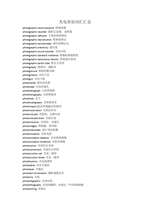
1.发光二极管一个发光二极管[1,2]是一个PN结的半导体发光时正向偏置。
图6.1显示的连接器件、电路符号,能量块和二极管关联。
能带理论提供了对一个)简单的解释半导体发射器(和探测器)。
允许能带通过的是工作组,其显示的宽度能在图中,相隔一禁止区域(带隙)。
在上层能带称为导带,电子不一定要到移动单个原子都是免费的。
洞中有一个正电荷。
它们存在于原子电子的地点已经从一个中立带走,留下的电荷原子与净正。
自由电子与空穴重新结合可以,返回的中性原子状态。
能量被释放时,发生这种情况。
一个n -型半导体拥有自由电子数,如图图英寸6.1。
p型半导体有孔数自由。
当一种P型和一种N型材料费米能级(WF)的P和N的材料一致,并外加电压上作用时,产生的能垒如显示的数字所示。
重参杂材料,这种情况提供许多电子传到和过程中需要排放的孔。
在图中,电子能量增加垂直向上,能增加洞垂直向下。
因此,在N地区的自由电子没有足够的能量去穿越阻碍而移动到P区。
同样,空穴缺乏足够的能量克服障碍而移动进入n区。
当没有外加电压时,由于两种材料不同的费米能级产生的的能量阻碍,就不能自由移动。
外加电压通过升高的N端势能,降低一侧的P端势能,从而是阻碍减小。
如果供电电压(电子伏特)与能级(工作组)相同,自由电子和自由空穴就有足够的能量移动到交界区,如底部的数字显示,当一个自由电子在交界区遇到了一个空穴,电子可以下降到价带,并与空穴重组。
电子信息工程专业英语翻译清华出版社EnglishforITandEE03

will experience a force (in a similar way that planets
experience a force in the gravitational field of the Sun). If
电子信息工程专业英语 翻译清华出版社
EnglishforITandEE03
2020/11/27
电子信息工程专业英语翻译清华出版 社EnglishforITandEE03
Unit 3
EM Fields, Antenna and Microwaves
电子信息工程专业英语翻译清华出版 社EnglishforITandEE03
two locations. For instance, the metal atoms in a radio
transmitter appear to transfer energy continuously. This view
is useful to a certain extent (radiation of low frequency), but
Part I
Electromagnetic Field
电子信息工程专业英语翻译清华出版 社EnglishforITandEE03
New Words
vicinity 邻近,附近 charge 电荷 photon 光子 atom 原子 catastrophe 大灾难,大祸 emission 发射,散发 incident 入射的 electrodynamics 电动力学 gravitational 重力的
•随着时间的推移,人们认识到 电场和磁场是电磁场这一整体 的两个部分。
电子信息工程专业英语翻译清华出版 社EnglishforITandEE03
- 1、下载文档前请自行甄别文档内容的完整性,平台不提供额外的编辑、内容补充、找答案等附加服务。
- 2、"仅部分预览"的文档,不可在线预览部分如存在完整性等问题,可反馈申请退款(可完整预览的文档不适用该条件!)。
- 3、如文档侵犯您的权益,请联系客服反馈,我们会尽快为您处理(人工客服工作时间:9:00-18:30)。
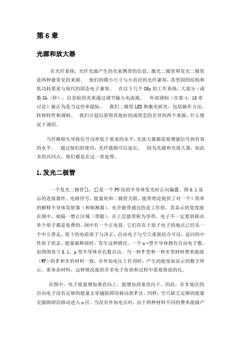
the spectrum. Similar results are shown for GaInP/AlGaInP QWs, while photon coincidence experiment verifies the simultaneity of TPE.
Fig. 1. Bulk GaAs TPE measurements and calculations with optical pumping by 514nm Ar laser: (a) 100mW pump spontaneous and singly-stimulated TPE at different wavelengths with 0.2mW stimulation power. The solid arrows indicate the stimulating photon energies and the dashed arrows indicate the theoretical stimulated photon central energies.(b) 180mW pump spontaneous and singly-stimulated TPE with various stimulation powers at 1310nm.The inset is a schematic description of singly-stimulated TPE energy broadening in bulk semiconductor.
We report the first experimental observations of two-photon emission from semiconductors, to the best of our knowledge, and develop a corresponding theory for the room-temperature process. Spontaneous two-photon emission is demonstrated in optically-pumped bulk GaAs and in electrically-driven GaInP/AlGaInP quantum wells. Singly-stimulated two-photon emission measurements demonstrate the theoretically predicted two-photon optical gain in semiconductors - a necessary ingredient for any realizations of future two-photon semiconductor lasers. Photon-coincidence experiment validates the simultaneity of the electrically-driven GaInP/AlGaInP two-photon emission, limited only by detector’s temporal resolution.
1
Two-photon emission (TPE) is a process in which electron transition between quantum levels occurs via simultaneous emission of two photons. This phenomenon is important for astrophysics and atomic physics 1, 2, while semiconductor TPE was recently proposed as a compact source of entangled photons, essential for practical quantum information processing
filtering out spontaneous infrared emission) onto a ~200µm thick GaAs sample (much thicker than the laser penetration depth), inducing ~1.2·1018cm-3 local carrier concentration, while the pump-induced sample heating is estimated to be ~330K. The pump laser was chopped at 236Hz, and the collected emission from the sample in a transmission configuration was detected by a New-Focus infrared (IR) femtowatt photoreceiver via a lock-in amplifier. The spectrum was obtained by an Acton-Research monochromator using a 1600nm-blazed grating and ~10nm spectral resolution. The measured spectrum for the TPE was very wide as expected (Fig. 1-a) complying with the theory described below, while the overall collected optical power was ~3nW. In order to validate unambiguously that the observed luminescence is indeed a TPE, and to dismiss any possibility of inhomogeneously broadened emission from midgap levels, we measured singly-stimulated TPE by launching a specific wavelength into the optically pumped GaAs. As a result of this excitation, a complementary TPE wavelength peak appeared. In all the stimulated TPE experiments only the carrier density was modulated for lock-in detection, whereas the stimulating lasers were not modulated, while the observed signals were proportional to the pump power. Stimulation with 0.2mW 1630nm (0.761eV) laser resulted in a peak at 1451nm (0.854eV), while a 1600nm (0.775eV) laser yielded a peak at 1476nm (0.84eV) (Fig.1-a). In both cases the photon energies are complementary about the center of the spontaneous emission at 0.81eV within a ~3meV error, as expected due to energy conservation. Changing the stimulation wavelength to 1570nm (0.79eV) caused the stimulating and the complementary peaks to merge approaching the degenerate case. The peaks appeared to
3-5
, three orders of magnitude more efficient6 than the existing
down-conversion schemes. Two-photon absorption in semiconductors has been substantially investigated7-11; however spontaneous semiconductor TPE has been neither observed nor fully analyzed theoretically so far. Two-photon transition is basically much weaker than the related first-order process. Therefore observations of multi-photon spontaneous decays have so far been restricted to a few atomic transition cases, where the lowest-order transition is forbidden by selection rules16 or suppressed by a cavity17, while their two-photon spectrum is continuous and centered at about half the one-photon transition frequency
Байду номын сангаас
3
In our first experiment, we optically pumped GaAs by a 100mW continuous wave (CW) 514nm argon laser ( ℏω pump ≈ 1.73Egap ), focused with ~30µm spot size (after