4H - Control & Monitoring of Cost and Schedule
控制计划Control Plan
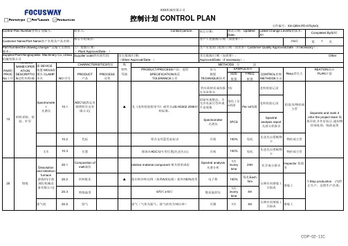
制订日期:共6页第1页SPEC特殊CHAR特性PRODUCT/PROCESS产品、进程EVALUATION/评估与PRODUCT PROCESS CLASS等级SPECIFICATION规范MEASUREMENT测量SIZE FREQ CONTROL控制产品过程TOLERANCE公差TECHNIQUE技术数量批量METHODS方法供应商材质成份报告及质保书1份进料检验记录铝锭外观整洁,不允许有油污等外观不良现象每托上层+四周进料检验记录10.2色标铝合金用蓝色标标识目视100%每托先进先出看帐物卡物控部主管叉车10.3位置摆放在ADC12专用位置(先进先出)目视100%每托先进先出看帐物卡物控部主管20.1Composition ofmelt成份relative material component 相关材质成份Spectral analysis光谱分析1次/everytime24H化学成分报告Inspector 检验员20.2回料配比▲新旧料回料比例(按照A级标准)新料100%使用电子称100%每扎Eachfirm20.3熔炼温度670℃±15℃数显温控仪1次/everytime4H除气机20.5除气除气(气体为氮气、除气时间为10分钟)目测1次4H 压铸车间熔炼工日报表熔炼工Customer Name/Part Name客户名称及产品名称:核心小组成员:客户工程批准/日期(如需要):Part Number/the drawing change产品编号及图纸版本:工厂批准/日期:( Plant Approve/Date:)客户质量部门批准/日期(如需要)Customer Quality Approved/Date(if necessary):控制计划 CONTROL PLAN文件编号:XX-QR/4-PD-075(A/0)Control Plan Number控制计划编号:联系人: Contact person:修改日期:UpdatedDate:Latest Change Level编制版本:A1Completed By编制:Supplier/Plant:Ningbojialilai Machinery Co.,Ltdxxx 机械有限公司Supplier code供应商代码:其它批准/日期:(Other Approval/Date: )其它批准/日期(如需要): OtherApproved/Date(if necessary):PART/ PROC No工序PROCESSNAME/OPERATIONDESCRIPTION过程名称/操MACHINE机器 DEVICE装置 MOULD模具 CLAMP夹具CHARACTERISTICS特征METHODS 方法NO 序号SAMPLE抽样Resp责任人REATION反应PLAN计划10材料采购、检验、贮存Spectrometer光谱仪10.1ADC12(清远市顺博铝合金有限公司)20熔炼Dissolutionand retentionfurnace溶炼炉(宁波湘恒机械设备有限公司)1.Stop production (1)停止生产,反馈生产经理;压铸车间熔炼工日报表熔炼工▲见《进料检验指导书》或符合JIS H5302 2006材料标准。
2.5 样件控制计划

零件名称/描述:CROSS SHAFT,U222
供应商/工厂批准/发布 10-12-2005
客户质量批准/日期
Supplier Plant 供方/工厂 公司
Supplier Plant Code - Other Approval/Date(If req'd.) 供方代号 PLM0012 其它批准/日期(如需要〕
Other Approval/Date(If Req'd.) 其它批准/日期(如需要〕
Proce ss N0. 过程 号
Process Name/Operation
Description 过程名称/过程描述
Machine,De Control Characteristics 控制参数
vice,Jig,Too
如发现异常,进行隔离及时通 知检验员处理。 及时追查,重新写明; 如有异常,隔离禁止使用;重
新拌料满足生产需求 如有异常,停止使用,及时换
料;
调整成型条件,通知注塑主管 、质保主管处理;
60
成型
注塑成型机 5
外观
产品表面无明显划痕、熔接痕, 不可有缺料、脏污;
目视检查
首件(一模); 巡检(一模/一
次);自检 (100%)
Speci
ls For Mfg. NO 生产的机器/ 编
设备/工装 号
A.Product A.产品
B.Process 过程
al Char Class
Product/Process/Specification/ Tolerance
产品/过程/规范/公差
特性
1 核对来料牌号
无牌号错误
Method 方法
Evaluation/Measure
FPC-QC工程图(英文版)1

《钻头检验作业指 导书》Drill bit
inspection operating instructions
游标卡尺Vernier caliper 40X放大镜
40X magnifier
《钻头检验作业指 导书》Drill bit
inspection operating instructions
IQC来料检查记录 IQC Incoming inspection records
文件名称 Document title
制 定Prepared by:
QC Engineering chart
审 核Checked by:
Document NO. 文件编号:
XC-WI-PZ(IPQC)-25
版本Version:
A
页次Page:
1/12
批 准Approved by:
产品流程编 号 Product flow No
原材料检查 Raw materials
inspection
IQC各来料检验作业 指导书 Incoming Material Inspection operating instructions for IQC
产品流程标准、公
特殊特性 差Product 评估/测量方法
Special
process
evaluation/measu
报废、返工 Scrapped and Reworked
1次/每班 Once/shift
温、湿度记录 Temperature and 调整Adjusted Humidity records
文件名称 Document title
制 定Prepared by:
QC Engineering chart
采用体外染色体畸变试验检测锐钛型纳米二氧化钛的遗传毒性
收稿日期:2021-08-12;修订日期:2021-11-16作者信息:杜秀明,E-mail:**********。
*周庆云,E-mail:**********采用体外染色体畸变试验检测锐钛型纳米二氧化钛的遗传毒性杜秀明1,2,洪丽玲1,2,徐灵芝1,2,周庆云1,2,* (1.上海化工研究院有限公司,上海200062;2.上海化工院检测有限公司,上海200062)In vitro chromosome aberrationevaluation of anatase titaniumdioxide nanoparticlesDU Xiuming1,2,HONG Liling1,2,XU Lingzhi1,2,ZHOU Qingyun1,2,*(1.Testing Center,Shanghai Research Institute of Chemical IndustryCo.,Ltd.,Shanghai200062;2.Shanghai Institute of ChemicalIndustry Testing Co.,Ltd.,Shanghai200062,China)【摘要】目的:按《OECD化学品测试准则473:体外哺乳动物染色体畸变测试》的要求进行试验,检测锐钛型纳米二氧化钛诱发体外培养的哺乳动物细胞染色体畸变的能力,以评价其是否属于致突变物。
方法:试验组受试物终浓度分别设置为0.0078、0.0312、0.125、0.5和2mg/mL,同时设立溶剂对照组和阳性对照组。
试验分为有代谢活化系统短时处理组(+S9,4h)、无代谢活化系统短时处理组(-S9,4h)和无代谢活化系统连续处理组(-S9,24h)3种处理方式,将培养的中国仓鼠肺细胞(CHL)暴露于锐钛型纳米二氧化钛混悬液中,染毒相应时间后收获细胞,经低渗固定后,制片并染色。
每个浓度组选取300个分散良好的中期分裂相细胞进行染色体畸变分析。
锐鼎AMA系列扬声器电路板用户手册说明书

ByAMA12004H/AMA12004H AMA6002H/AMA12002H/AMA24002HOWNER’S MANUALFEATURES & SPECIFICATIONSFEATURES• Class A/B MOSFET Power Amplifier• 2 Ohm stable• MOSFET High Speed Switching Power Supply• RCA (Low Level) Inputs• Bridgeable• Input Sensitivity: 200mV - 8V• Optional Item: Bass Boost Control• 4-Way Protection Circuitry: Thermal, Short Circuit, Overload, & DC OffsetRECOMMENDED FUSE SIZE(AMA6002H: 20 x 1) (AMA12002H: 20 x 2) (AMA24002H: 30 x 2) (AMA12004H: 20 x 2) (AMA24004H: 30 x 2)POWER OUTPUTAMA6002H :600 Watts Achievable Power 75 x 2 @ 4 Ohms RMS 150 x 2 @ 2 Ohms RMS300 x 1 @ 4 Ohms RMSAMA12002H :1200 Watts Achievable Power 150 x 2 @ 4 Ohms RMS 300 x 2 @ 2 Ohms RMS600 x 1 @ 4 Ohms RMSAMA24002H:2400 Watts Achievable Power 300 x 2 @ 4 Ohms RMS 600 x 2 @ 2 Ohms RMS1200 x 1 @ 4 Ohms RMSDIMENSIONSAMA6002H (W x H x D): 8.95” x 8.48” x 2.64” 227.5 x 215.5 x 67mm AMA12002H (W x H x D): 8.95” x 8.48” x 2.64”227.5 x 215.5 x 67mm AMA24002H (W x H x D): 11.57” x 8.48” x 2.64” 294 x 215.5 x 67mm AMA12004H (W x H x D): 12.09” x 8.48” x 2.64” 307 x 215.5 x 67mm AMA24004H (W x H x D): 12.09” x 8.48” x 2.64”307 x 215.5 x 67mm• Variable High Pass Filter: 50Hz - 750Hz • Variable Low Pass Filter: 50Hz - 120Hz • Sub Sonic Control: 20Hz - 50Hz • Bass Boost Control: 18dB • Variable Bass Control remote: 0dB - 18dB • Phase Shift Switch: 0º - 180ºAMA12004H:1200 Watts Achievable Power 75 x 4 @ 4 Ohms RMS 150 x 4 @ 2 Ohms RMS 300 x 2 @ 4 Ohms RMS AMA24004H:2400 Watts Achievable Power 150 x 4 @ 4 Ohms RMS 300 x 4 @ 2 Ohms RMS600 x 2 @ 4 Ohms RMSCONTROLS & FUNCTIONS11101659148671A M A 6002H342CONTROLS & FUNCTIONSA 12002H1110165914867151342CONTROLS & FUNCTIONSA 24002H1110165914867151342CONTROLS & FUNCTIONSA 12004H165109148671342CONTROLS & FUNCTIONSA 24004H165109148671342CONTROLS & FUNCTIONSLRAMA6002H AMA12002H AMA24002H1. Speaker TerminalsCH1CH2CH3CH4BridgedBridged CH1 CH2 CH3 CH4AMA12004H AMA24004HThese chrome plated connectors can accept from 16 to 8 gauge wire. Be careful to observe proper polarity when connecting the cables2. B - Terminal (Chassis ground)R E MB A TT G N DPOWERAMA6002HAMA12002H AMA24002H AMA12004H AMA24004HTo avoid unwanted ignition noise caused by ground loops, it is essential that the amplifier be grounded to a SPEAKER BridgedR E MB A TT G N DPOWER3. Remote Turn-On InputR E MB A TT G N DPOWERTo remote or power antenna output of car stereo. This amplifier is turned "ON" remotely when the vehicle's stereo is turned "ON".Note: IF YOUR RADIO DOES NOT HAVE +12 VOLT OUTPUT LEAD WHEN THE RADIO IS TURNED ON, THE "REMOTE" TERMINAL ON THE AMPLIFIER CAN BE CONNECTED TO THE VEHICLE'S ACCESSORY CIRCUIT THAT IS LIVE WHEN THE KEY (IGNITION) IS "ON".4. B+ Terminal (Battery Positive)5. Input Sensitivity AdjustmentDue to the power requirements of the amplifier, this connection should be made directly to the positive (+)terminal of the battery. For a safety measure, install an in-line fuse holder (not included) as close to the battery positive (+) as possible with an apmere rating not to exceed the total value of fuses in the amp.MINMAXMIN MAXMINMAXThis control adjusts the amplifier's sensitivity to match the signal strength coming from the source unit. Input sensitivity is variable from 200 Millivolts to 8 volts. Clockwise increases sensitivity. Counterclockwise decreases sensitivity. THE KNOB IS NOT A VOLUME CONTROL . A lower signal level will require increased sensitivity for AMA6002HAMA12002H AMA24002H AMA12004H AMA24004HAMA6002HAMA12002H AMA24002H AMA12004H AMA24004HAMA6002H AMA12002H AMA24002HAMA12004H AMA24004HCONTROLS & FUNCTIONSCONTROLS & FUNCTIONS 50 15050 15050 150AMA6002HAMA12002H AMA24002H AMA12004H AMA24004HAMA6002HAMA12002H AMA24002H AMA12004H AMA24004HAMA6002HAMA12002H AMA24002H AMA12004H AMA24004HAMA6002HAMA12002H AMA24002H AMA12004H AMA24004HAMA6002HAMA12002H AMA24002H AMA12004H AMA24004HCONTROLS & FUNCTIONSCONTROLS & FUNCTIONS12. Remote Bass Knob Port Fig 1DVM REMOTE14. Bass Boost SwitchBASS BOOST ON OFFBASS BOOST ON OFF ON OFFBass Boost Control (MIN / MAX) : OptionalBass Boost Switch: ON and OFF AMA6002HAMA12002HAMA24002HAMA12004HAMA24004HCONTROLS & FUNCTIONS16. LED indicator (Status)POWERPROTECT-PWR (Power) : This BLUE LED will illuminate when the amplifier is turned "ON". If it fails to illuminate, check the power connections to the amplifier and fuses.- PROT (Protection) : The amplifier protection circuitry will disable the amplifier if input overload, short circuit, or extremely high temperature conditions are detected. When the protection mode is in operation, the LED indicator on the side panel will be illuminated, indicating the amplifier has gone into a self-preservation mode.If you observe that the protection LED is lit, please check the system carefully to determine what has caused the protection circuit to engage. The amplifier shut down due to a thermal overload condition, please allow it to cooldown before restarting. If the amplifier shut down because of an input overload or short circuit, be sure to repair these conditions before attempting to power up the amplifier again.Fig 2.LINE CODEOptional Remote Bass Boost ControlMIN MAXPLANNING/MOUNTING YOUR SYSTEMPlanning Your SystemBefore beginning the installation, consider the following:a. If you plan to expand your system by adding other components sometime in thefuture, ensure that adequate space is left, and cooling requirements are met.If your radio/source is equipped with Pre-Amp outputs, it is possible to utilizethem to drive an Amplifier and connecting (Amplifier) to the 2 rear speakers.Then, use the built-in power of your radio to drive the 2 front speakers.NOTE:DISTORTION LEVEL IS CONSIDERABLY LOWER FROM PRE-AMP (LOW LEVEL) OUTPUTS, THAN SPEAKER (HIGH LEVEL) OUTPUTS.b. Are your components matched? The RMS power rating of your speakers mustbe equal or greater than the Amplifier’s. They also must be 1-8 Ohmsimpedance (this information is normally printed on the speaker magnet).c. Consider both the length of your leads, and routing when determining the mountinglocation. Pre-Amp input Jacks require a length of high quality shielded male to maleRCA patch cord.Mounting Your SystemThe mounting position of your Amplifier will have great effect on its ability to dissipate the heat generated during normal operation. It has an ample heat sink for heat dissipation, and also is designed with a thermal shut-down (for heat protection) circuit, having enough air directed over the cooling fins will improve heat dis-sipation dramatically. DO NOT enclose the amplifier in a small box or cover it so that air can not flow around the fins. Temperatures in car trunks have been measured as high as (155˚F) in the summer time. Since the thermal shut-down point for the Amplifier is (158˚F) it is easy to see that it must be mounted for maximum cooling capability. To achieve the maximum advantage of convection air flow in an enclosed trunk, mount the amplifier in a horizontal position. Cooling requirements are considerably relaxed when mounting inside the passenger compartment since the driver will not allow temperatures to reach a critical point. Floor mounting under the seat is usually satisfactory as long as there is at least 1 inch (2.54cm) above the Amplifier’s fins for ventilation.a. Select a sutable location that is convenient for mounting, accessible for wiring and hasample room for air circulation and cooling.b. Use the amplifier as a template to mark the mounting holes. Remove the amplifier anddrill holes. Use extreme caution. Inspect underneath the surfaces before drilling!c. Secure the Amplifier using the screws provided.CAUTION: Before connecting any wires to the amplifier, disconnect the ground lead fromthe battery. Leave the ground lead disconnected until you are done wiring theamplifier.AMA6002H / AMA12002H / AMA24002HSTEREO MODETRI MODELRB R I D G ED LEFT SPEAKER2~8 OHM RIGHT SPEAKER 2~8 OHMLRB R I D G E D SUBWOOFER4~8 OHMLRB R I D G E D LEFT SPEAKER 4~8 OHM RIGHT SPEAKER 4~8 OHMBRIDGED4~8 OHMMONO MODE: I N D U C T O R L O W P A S S F I L T E R : C A P A C I T O R H I G H P A S S F I L T E RWIRING DIAGRAMWIRING DIAGRAMAMA12004H / AMA24004HCH1SPEAKER 2~8 OHMCH3 SPEAKER2~8 OHMCH2 SPEAKER 2~8 OHMCH4SPEAKER 2~8 OHMCH1 SPEAKER SPEAKER 2~8 OHMCH22~8 OHMBRIDGED4~8 OHMBRIDGED 4~8 OHMC H 1 C H 1 C H 4C H 4C H 3 C H 3C H 2 C H 2 B R ID G ED B R ID G ED C H 1 C H 1 C H 4C H 4C H 3 C H 3C H 2 C H 2 B R ID G ED B R ID G ED C H1 C H 1 C H 4C H 4C H 3 C H 3C H 2 C H 2 B R ID G ED B R ID G ED 2 CHANNEL MODE3 CHANNEL MODE4 CHANNEL MODEBRIDGED4~8 OHMFREQUENCYINDUCTOR CAPASITOR 80Hz 7.5 mH 470uF 100Hz 6.5 mH 330uF 120Hz 5.5 mH 330uF 150Hz4mH220uFCOMPONENT VALUES FOR 6 dB PASSIVE CROSSOVERBRIDGED 4~8 OHMBRIDGED 4~8 OHMC H 1 C H1 C H 4C H 4C H 3C H 3C H 2 C H 2CH3 SPEAKER 4~8 OHMCH4SPEAKER 4~8 OHMCH2 SPEAKER 4~8 OHMCH1SPEAKER 4~8 OHM: I N D U C T O R L O W P A S S F I L T E R : C A P A C I T O R H I G H P A S S F I L T E RAMA12004H / AMA24004H6 CHANNEL MODEWIRING DIAGRAMADJUSTMENTS AND TUNING Below you will find information on adjusting the amplifiers gains. Adjusting the gain correctly is essential to proper operation of the amplifier. If the gain is not adjusted properly it can and will lead to damage of the amplifier and connected speakers and will void your MANUFACTURER WARRANTY. The gain on an amplifier is not a volume control. It is a signal level setting that tells the amplifier how strong of a signalis coming from the head unit. Your amplifier has an input sensitivity of 200mV-8V. The minimum setting is8V and the maximum setting is 200mV. Minimum meaning the head unit or processor has 8V output and the maximum meaning it has a 200mV output.When using Low-Level (RCA) inputs you MUST know what the pre-out or line-out voltage of your headunit is rated in Volts. This is not the wattage rating. This can be found in the manual of the head unit or by contacting the manufacturer. If you are using a line-driver or another type of processor that adjusts the output voltage of the signal to the amplifier you will need to know what the output is adjusted to. The gain on the amplifier needs to be set proportionately to the pre-out or line-out voltage rating of the head unit or processor.If the signal strength is 4V then the gain would be adjusted to about 45 - 50%. Below is a list of commonly found voltage ratings and their appropriate gain adjustments. When adjusting the gain you want to start with the bass boost setting on the amp set to minimum and bass adjustments on the head unit or processor are set at 0 or flat. As these other settings for bass adjustments are increased, the gain setting will need to be adjusted lower.2V ≥ 70%4V ≥ 45%5V ≥ 32.%8V ≥ 5% (Bass boost must be left at minimum on the amp and 0 or flat on the head unit or processor)10V ≥ Can not be used with this amplifier.If your amplifier includes Hi-Level (speaker wire) inputs and you are using them for the audio signal connec-tion, please use the below steps to adjust the amplifier. Start with a song with good bass that you know very well.1. Use a screwdriver to turn GAIN (8V / 0.2V fully counter clockwise to 8V2. Turn the auto sound system’s volume control to about 3/4 of its full range. Any higher normallyleads to the signal being distorted.3. Turn up the amplifiers gain / level control unit the sound begins to distort, then immediately gain /level down to a point just before where the distortion began.4. Adjust the auto sound system’s volume control to a comfortable listening level and you are good to go.NOTE: The steps to adjusting the gain / level control need to be repeated when you adjust any bass boost setting on the amplifier, processors or significantly on the head unit. Adjusting bass boost settings signifi-cantly without adjusting the gain / level can lead to a distorted signal and damage to the amp and speakers.Separate speaker wires and insulateSpeaker wires shortSTATUS LAMP ONTemperature shut downBe sure proper speaker load impedance recommendations are observed.(If you use an ohmmeter to check speaker resistance, pleaseremember that DC resistance and AC impedance may not be the same.)AMPTURNING OFF MEDIUM/HIGH VOLUMEimpedanceCheck speaker load Reverse Left and Right RCA inputs to determine if it is occurring before the amp.Check Audio LeadsNO SOUND IN ONE CHANNELInspect for short circuit or an open connection.Check Speaker Leads Fuse broken wire with receiver on No power to remoteAMP NOTSWITCHING ON No power to power wire Is the DiagnosticLED illuminated ? ( YES )NO SOUND Is the powerLED illuminated ? ( NO )Check fuses in amplifier.Be sure Turn-on lead is connected Check signal leads. Check gain control.Check Tuner/Deck volume level.Clean contacts on fuse holders.CHECK POINTS CURESYMPTOMS Check for speaker short or Amplifier overheating.Repair power wire or connections.Turn radio downReplace fuse.Check connections to radio. TROUBLESHOOTINGAUDIOBAHN AMPLIFIERS CAR AMPLIFIERS。
奥硝唑注射液接瓶头孢噻肟钠注射液的稳定性研究

奥硝唑注射液接瓶头孢噻肟钠注射液的稳定性研究王穗琼;肖大立;赖月云【期刊名称】《国际医药卫生导报》【年(卷),期】2010(16)7【摘要】Objective To investigate stability of compatibility of ornidazole injection instilled after cefotaxime sodium for injection.Methods Cefotaxime sodium for injection mixed ornidazole injection with different quality proportion.The appearance of mixtures were observed at 25℃ for 4h.Drugs mixed drugs,and control articles mixed controlarticles.Cefotaxime sodium for injection mix ornidazole injection with the quoity proportion of 1 to 2.The appearance and pH value of mixtures were observed at 25℃ for 75min.Results The mixtures with cefotaxime sodium for injection and ornidazole injection with the quality pro-portion of 2 to 1-1 to 100 were change from light yellow clear liquid to light pink clear liquid at 25℃for 4h.The mixtures of drugs with the quality proportion of 1 to 2 changed from light yellow clear liquid to light pink clear liquid at 25℃ in 40min,but the colour of the control articles were same in 75min.There were no significiant changes in pH value.Conclusion Avoid ornidazole injection instilled after cefotaxime sodium for injection.Instill 0.9%sodium chloride for injection 20ml before ornidazole injection.%目的考察奥硝唑注射液接瓶头孢噻肟钠注射液的稳定性.方法采用头孢噻肟钠与奥硝唑按照不同质量比配伍,观察配伍液在25℃ 4 h内外观的变化.药品与药品、对照品与对照品以1:2质量比配伍,观察配伍液在25℃75 min内外观的变化,并每15 min测量配伍液的pH值.结果头孢噻肟钠与奥硝唑以2:1-1:100质量比配伍,在25℃4 h内配伍液颜色由微淡黄色澄清液变成淡粉色澄清液;以1:2~1:10质量比配伍在25℃ 1 h内颜色由微淡黄色澄清液变成淡粉色澄清液;以1:2质量比配伍,药品的配伍液在40 min 由微淡黄色澄清液变成淡粉色澄清液,对照品的配伍液在75 min内无改变,二者pH 值变化不明显.结论奥硝唑氯化钠注射液接瓶头孢噻肟钠注射液发生的变色反应由辅料产生.临床使用时应避免奥硝唑注射液直接与头孢噻肟钠注射液接瓶,如果需要接瓶,建议接瓶前用注射用0.9%氯化钠注射液20ml冲管.【总页数】4页(P846-849)【作者】王穗琼;肖大立;赖月云【作者单位】510010广州,广东省妇幼保健院药剂科;510010广州,广东省妇幼保健院药剂科;510006广州,广东药学院【正文语种】中文【相关文献】1.注射用头孢唑肟钠与奥硝唑注射液的配伍稳定性研究 [J], 张晓钰;刘冬;张晋;刘子昀;姜凤丽;乌伊萍2.奥硝唑注射液与常用注射液的配伍稳定性研究 [J], 张晓华3.注射用头孢噻肟钠与奥硝唑注射液存在配伍禁忌 [J], 康艳清;蔡雪花4.注射用头孢噻肟钠舒巴坦钠与奥硝唑注射液存在配伍禁忌 [J], 邓志华;邹永超;王超英;谢媛媛5.奥硝唑注射液与头孢噻肟钠的配伍稳定性考察 [J], 徐济萍;李军;张辉;张敏因版权原因,仅展示原文概要,查看原文内容请购买。
婴幼儿择期手术前禁饮食最佳时间的临床

Abstract Objective:To probe into the best time of preoperative fasting for
elective surgery in children and the influence of prolonged fasting on the body of the infants.Methods:The best time for elective surgery in children
全身麻醉术前禁饮 食 的 目 的 是 防 止 术 中、术 后 因 呕 吐 物 误 吸致窒息的发生[1]。婴幼儿由于代谢旺盛,体液丧失较快,如 禁
1.2.3 评价方法 由责任护士记录患儿的一般情况,实际 禁 饮 食的起止时间,患儿禁食后的哭闹时间及家长焦虑情况,记录 麻
甲基丙二酸尿症的神经毒理机制研究及致病基因突变位点分析
华 中 科 技 大 学 博 士 学 位 论 文甲基丙二酸尿症的神经毒理机制研究及致病基因突变位点分析中文摘要第一部分甲基丙二酸对大鼠心肌线粒体呼吸链复合酶Ⅱ的影响 【目的】甲基丙二酸尿症患者常常出现基底神经节特别是苍白球的变性坏死,研究显示这种特发性的神经损害可能与该病中累积的甲基丙二酸(MMA)、丙二酸、2-甲基柠檬酸等内源性毒性产物影响线粒体呼吸链的能量代谢及三羧酸循环有关。
本次研究旨在探讨甲基丙二酸在线粒体能量代谢中的作用及可能的神经毒性作用机制。
【方法】使用差速离心法在体外构建大鼠心肌线粒体模型,用Bradford蛋白浓度测定法测定和调节线粒体蛋白浓度。
用分光光度法和Western blot方法分别测定不同浓度(0 mM,1 mM,2.5 mM和5 mM)和不同时间(30 min,2 h,4 h和8 h)孵育的甲基丙二酸对大鼠心肌线粒体呼吸链复合酶Ⅱ(complex Ⅱ)的活性改变和其两种蛋白亚基铁硫蛋白30亚基(IP)、黄素蛋白70亚基(FP)表达水平的影响。
【结果】1.酶活性检测结果①甲基丙二酸孵育30 min和2 h时,各不同浓度处理组(1 mM,2.5 mM,5 mM)的complexⅡ活性与对照组相比均无显著性降低(P 均> 0.05);②甲基丙二酸孵育4 h时,各不同浓度处理组的complex Ⅱ活性与对照组相比均有明显降低(P均<0.05);③甲基丙二酸孵育时间延长至8 h时,低剂量甲基丙二酸处理组(1 mM)的complex Ⅱ活性与对照组相比无显著性降低(P>0.05),而中、高剂量组(2.5 mM,5 mM)与对照组相比则有显著降低(P均< 0.05);④甲基丙二酸孵育30min, 2 h, 4 h时各不同MMA浓度组的complexⅡ的活性值处于较华 中 科 技 大 学 博 士 学 位 论 文稳定的水平,未见明显降低(P均> 0.05);当孵育时间增加到8 h时,各浓度组的complexⅡ的活性值可见明显下降(P均< 0.05)。