友力发YLF320240A-GB中文字库LCM使用说明书
液晶模块320240带中文字库

MW320240D 带中文字库液晶显示模块使用说明书
----------------------------------------------------------------------------------------------
南京名闻科技有限公司 025-84402170 季先生
目录
1. 简介...................................................................................................................................................3 2. 引脚说明...........................................................................................................................................4 3. 微控制器(MCU)的接口...................................................................................................................5
3.1 8080 系列的 MCU 接口 ........................................................................................................5 3.2 6800 系列的 MCU 接口 ...............................
LC中文说明书
再按“”弹出
如为最后一级菜单,界面不会出现黑色滚动条,按返回键“RT”返回上级菜单
或主界面。如在某一界面停止操作,数秒钟后自动返回主界面。
用“”、“”移动键、确认键“”和返回键“RT”根据上述方法可完全观察
到运行时间、本次运行时间、维护参数、历史故障、出厂日期、现场故障等运行参数
并返回到上级菜单。
断相保护时间
0005
缺相时间设定≥20秒时,缺相不起作用。如不平衡保护起作用,不平衡保护会动作。
过载重启延时
0000分钟
如电机过载停机,为避免电机频繁启动,无论掉电或复位都要经过此延时才能开机
出厂日期
****年**月**日
厂家输入设备的出厂日期
出厂编号
******
厂家输入设备的出厂编号
9、控制器指示灯说明
当环境温度低于10℃时的首次启动,应先把PLC控制器设为手动
模式启动进行空载运转5分钟预热机器,再停机改变PLC控制器为自
动加载模式后进入正常运行!
二、控制面板说明及操作(SEC微电脑专用控制器)
1、通电:按说明书接线并检查无误后接通电源,把红色停止按钮往顺时针方向转动通电。通电后,画面首先显示“申行健”,5秒后进入现场主画面,显示现场温度,压力值以及故障状态,如无任何故障,显示屏底部将显示当前时间。如有故障将显示故障的名称,启动前应首先排除故障。开机2分钟后或停止按键操作2分钟后,背光电源关断,按“RT”键背光将再次点亮。
尊敬的用户:
首先,我们感谢您选购SUCCESS ENGINE公司的SE系列螺杆式空气压缩机。
本公司的产品在出厂之前均已经过严格的检验和测试,但为了确保机器安全、可靠、耐久地投入运行,请您务必在使用本机器之前详细阅读本说明书,充分掌握该螺杆压缩机组操作规范和技能,使其设备长期处于良好的工作状态。
IFI 固态放大器商品说明书

1981IFI SOLID STATE AMPLIFIERSWide instantaneous frequency rangeGain controlBacklit LCD displayTotal/Operate Elapsed Time MeteringSelf-diagnostic circuitryVSWR protectionSafety Requirement of IEC-348Unconditionally stable against load mismatchesForward /Reflected Power IndicationIEEE 488 GPIB Remote ControlRF Door Safety InterlockAir-cooled (Integrated Forced Air – self-contained)Open Circuit and Short Circuit ProtectionModulation, AM, FM & PULSEFront Panel Controls and IndicatorsStandby/OperateLocal/RemoteEMI Filter built-inAmplifiers are supplied with an AC line cord to accommodate the power source; an operation & maintenance manual; and amplifier performance test data.The Front Panel is standard for RF Connectors and RF Sample Port. If this is not convenient, please advise the location at the time of order. We will be happy to serve you. Thank you!*GPIB IEEE-488 Remote Control is standard.If this is not convenient, please review & advise the GPIB option at the time of order. These other available options are at no charge. Thank you!a. GPIB IEEE-488 Remote Controlb. GPIB IEEE-488 and RS 232 Remote Controlc. GPIB IEEE-488 and RS 422 Remote Controld. GPIB IEEE-488 and RS 485 Remote ControlIFI Model ST81-50 Solid State/TWT (CW) Combination Amplifier SpecificationsFrequency Range: 1-8 GHz (operable down to 0.8 GHz – specify if desired at time of order)Bnd 1: 1-2 GHz (Solid State) Bnd 2: 2-8 GHz (TWT)Rated Power: 50 Watts minimum (70W typical)Gain @ rated power: 47 dBPrime Power: 100-240 VAC +/-10%, 50/60 Hz, Single Phase *Input/Output Impedance: 50 ohms (VSWR 2.0:1)RF Input/Output Connectors: Type N FemaleTemperature: 0º to 50º C (40º C @ 10,000 feet)Non-operating Temp: -20º to 70º C (50,000 feet max)Humidity: 95% without condensationAltitude: 10,000 feetCooling System: Air cooled, self containedModulation: AM/FM/PulseConfiguration: 19” Rack Mount; 19”W x 25.25”L x 10.5”HSpurious: -50dBc**Harmonics (nominal): Band 1: 0.8-2.0 GHz, -20 dBc @ linear power (35-40 Watts)Band 2: 2-3GHz: -3 to –8 dBc @ Rated Power3-6GHz: -8 to –15 dBc @ Rated Power6-8GHz: -15 to –25 dBc @ Rated PowerVSWR Protection against an output mismatch* Alternate Prime Power (specify at time of order)* GPIB IEEE 488 Remote ControlForward RF Sample Port on the Front Panel, type N-F(specify front or rear at time of order)Internal Pre-amplification to obtain rated output power with an input level of0dBm or less. RF Input/Output Connectors on the Front Panel(Specify front or rear at time of order)Internal Systems DiagnosticsElapsed Time Metering in hoursRF Safety Interlock, type BNCFeatures: Forward/Reflected Power Indication simultaneously on Front Panel display**-20dBc harmonics available with filters at an additional charge. The Filters can be external or band selectable via switches internal to the amplifier. The control can be via the front panel or over the GPIB remote bus.。
力计 FG-5005 商品说明书

5,000 g, tension & compression FORCE GAUGEModel : FG-5005ISO-9001, CE, IEC1010FEATURES* 5,000 g, g/oz/Newton.* Tension or Compression,Peak hold, Zero.* Positive/ Reverse display.* 5 digits LCD with back light.* RS-232 computer interface.* Full line accessories, optionaltest stand.* DC 1.5V battery ( UM-3, AA )x 6 or DC 9V adapter in.LUTRON ELECTRONIC5,000 g x 1 g, g/oz/Newton, RS232FORCE GAUGEModel : FG-5005FEATURES*Large LCD display with back light.Update time Fast Approx. 0.2 second.*5,000 g, wide capacity, high resolution, high accuracy,Slow Approx. 0.6 second.high repeatability.Over range Display show " - - - - " when in over*3 kind display unit : g, oz, Newton.Indicator range status.*Tension & compression capability .Data output RS-232 serial computer interface.*Peak hold ( Max. load ) can be held in display during Overload Max. 7 kg.make tension or compression measurement.Capacity*Zero button can operate both for normal measuring Full Scale Approx. 0.2 mm max.& the " peak hold " operation.Deflection*Full capacity zero (tare) control capability.Zero/tare Max. full capacity.*Fast/Slow response time push button.Control*Positive or reverse display direction select.Circuit Exclusive microprocessor LSI-circuit.*Full line accessories ( adapters ) are included.Power Supply 6 x 1.5 V AA (UM-3) size battery*Hand held & stand mounted gauges are available.or DC 9V adapter (not included).*Low power consumption gives long battery life.Power Approx. DC 28 mA*Build in low battery indicator.Consumption*Microprocessor circuit & exclusive load cell transducer.Transducer Exclusive load cell.℃℃℉℉*Over load protection.Operating0 to 50 ( 32 to 122 ).*RS-232 computer interface.Temperature*Built-in DC 9V power adapter input socket.Operating Less than 80% RH.*Professional test stand ( optional ).HumidityDimension 215 x 90 x 45 mm ( 8.5 x 3.5 x 1.8 inch ). SPECIFICATIONS Weight 650 g ( 1.43 LB )/with batteries. Display LCD ( Liquid crystal display ).Mounting Main instrument with mounting holes are5 digits, 16 mm ( 0.63" ) digit size.Holes provided on the back case, easy standBack light.mounting.Display Positive or Reverse direction, select by Accessories Operating manual ....................1 PC. Direction the push button on the front panel.Included Flat-head adapter......................1 PC. Function Tension & Compression (Push & Pull). Hook adapter ...........................1 PC.Normal force, Peak hold ( Max. load ).Cone head adapter ...................1 PC. Peak hold Will freeze the display value of the Chisel head adapter .................1 PC.Peak load ( Max. load ).120 mm extension rod...............1 PC. Zero Zero button can be operated both for Carrying case ...........................1 PC."normal force" or "peak hold" operation Optional * Test stand, Model : FS-1001Unit select g/oz/Newton Accessories* Wedge grip, Model : WG-01Measure5,000 g/176.40 oz/49.03 Newton.* RS232 cable, Model : UPCB-01 Capacity * USB cable, Model : USB-01 Resolution 1 g/0.05 oz/0.01 Newton.* Software for data logging & data Min. Display 3 g/0.10 oz/0.03 Newton. recorder.℃ Model : SW-U801-WIN.Accuracy ±( 0.4 % + 1 digit ), within 23±5.* Under the test weight on 3000 g & 5000 g.* Appearance and specifications listed in this brochure are subject to change without notice.**。
伺服电机说明书

SF 说明书目录1.前言 01.1 开箱 01.2 使用上注意事项 01.3 适用伺服马达 01.4 注意事项 (1)1.5 安装 (1)2.面板操作 (3)2.1 辅助功能模式 (4)2.1.1警报追溯模式之操作 (4)2.1.2清除警报追溯资料 (4)2.1.3寸动功能 (5)2.1.4检查软件版本 (5)2.1.5重新开机(Reset) (6)2.1.6输入接点显示 (6)2.1.7输出接点显示 (7)2.1.8参数56~59自动设定步骤一 (8)2.1.9参数56~59自动设定步骤二 (8)2.1.10使用者参数初始设定 (9)2.1.11Fn7、Fn8、Fn9功能锁住与开放 (9)2.2 使用者参数设定模式 (11)2.2.1驱动器使用者参数 (12)2.2.2控制器参数 (20)2.3 监视模式 (25)2.3.116位区段 (25)2.3.232位区段 (26)2.3.3PC通讯专用参数 (27)2.4 警报号码显示 (28)3.RS232联机 (30)3.1 通信协议 (30)3.2 通信功能 (30)3.2.1PCÅDriver (31)3.2.2PCÆDriver (32)4.接线 (34)4.1 CN1控制器接头 (34)4.2 CN2编码器接线 (37)4.3 CN1及CN2 电路 (37)接头 (39)4.4 RS2324.5 标准接线 (40)4.5.1位置控制 (40)4.5.2速度控制 (41)4.5.3扭力控制 (42)4.6 电源、马达接线 (43)4.6.1SF15、SF20、SF50、SF75 (43)4.6.2SF30A (44)5.外形尺寸图 (45)6.驱动器规格 (50)7.使用步骤 (51)7.1 位置模式使用步骤 (51)7.2 速度模式使用步骤 (52)8.当控制器用时特有的功能 (53)8.1 寸动 (55)8.1.1相关输入接点 (55)8.1.2相关参数设定 (55)8.1.3动作流程 (55)8.2 归原点 (56)8.2.1相关输入接点 (56)8.2.2相关参数设定 (56)8.2.3动作流程 (57)8.2.4归原点流程图 (58)8.3 点到点运动 (59)8.3.1相关输入接点 (59)8.3.2相关参数设定 (59)8.3.3动作流程 (61)8.4 通讯定位 (61)1. 前言这次承蒙惠购AC servo SF系列产品,至为感谢。
APF操作手册
德殷能源科技(上海)有限公司 4.4 外形及安装图 .............................................................................................................. 19
4.4.1 壁挂式外形及安装图............................................................................................ 19 4.4.2 柜式外形及安装图................................................................................................ 20 5 功能与操作界面说明 ............................................................................................................... 20 5.1 人机界面概述................................................................................................................ 20 5.2 启动画面......................................................................................................................... 21 5.3 主界面 ............................................................................................................................ 22 5.4 监控界面........................................................................................................................ 23 5.5 系统参数........................................................................................................................ 23 5.5.1 电源侧参数 ........................................................................................................... 24 5.5.2 负载侧参数 ........................................................................................................... 24 5.5.3 APF 侧参数 ............................................................................................................ 25 5.5.4 联机状态............................................................................................................... 26 5.5.5 设备参数................................................................................................................ 27 5.6 曲线显示 ......................................................................................................................... 28 5.7 参数设置 ......................................................................................................................... 29 5.7.1 补偿设置................................................................................................................ 30 5.7.2 内部参数................................................................................................................ 31 5.7.3 报警故障............................................................................................................... 35 5.7.4 LCD 设置 ............................................................................................................... 36 5.7.5 联机设置............................................................................................................... 37 5.7.6 诊断维护设置 ....................................................................................................... 38 5.8 事件记录 ......................................................................................................................... 38 5.9 操作说明 ......................................................................................................................... 39 5.9.1 上电检查................................................................................................................ 39 5.9.2 启动步骤............................................................................................................... 39 5.10 设备维护........................................................................................................................ 40 6 常见问题的处理....................................................................................................................... 41 6.1 异常处理说明.................................................................................................................. 41 6.2 常见故障处理.................................................................................................................. 42
星发电热盘501FF、502FF产品说明书

MODELS501FF, 502FFInstallation andOperation Instructions2M-Z16005 Rev. A 06/19501FF502FFThese appliances are intended to be used for commercial applications, forexample in kitchens of restaurants, canteens, hospitals, and in commercial enterprises such as bakeries, butcheries, etc., but not for continous mass production of food.CAUTION:Read the instuction manual before opperating the appliance.2These symbols are intended to alert the user to the presence of important operating and maintenance instructions in the manual accompanying the appliance.RETAIN THIS MANUAL FOR FUTURE REFERENCENOTICEUsing any part other than genuine Star factory supplied parts relieves the manufacturer of all liability.notice. Such revisions do not entitle the buyer to corresponding changes, improvements, additions or replacements for previously purchased equipment.Due to periodic changes in designs, methods, procedures, policies and without notice. While Star International Holdings Inc., Company exercises good faith efforts to provide information that is accurate, we are notresponsible for errors or omissions in information provided or conclusions provided, the user assumes all risks in connection with such use.MAINTENANCE AND REPAIRSContact your local authorized service agent for service or required maintenance.Please record the model number, serial number, voltage and purchase date in the area below and have it ready when you call to ensure a faster service.SAFETY SYMBOLModel No.Serial No.Voltage Purchase DateBusiness 8:00 am to 4:30 p.m. Central Standard Time Hours: Telephone:(800) 264-7827Fax: (314) 781-2714E-mail****************************Website:Service Help DeskAuthorized Service Agent Listing Reference the listing provided with the unitorfor an updated listing go to:Website: E-mail****************************Mailing Address: Star Manufacturing International Inc.265 Hobson Street Smithville, TN 37166 U.S.AThis equipment is designed and sold for commercial use only by personnel trained and experienced in its operation and is not sold for consumer use in and around the home nor for use directly by the general public in food service locations. For equipment to be used by the general public, please contact the factory.The Star-Max Electric Hot Plates are equipped for the voltage indicated on the nameplate mounted on the front panel. This unit is designed to operate on alternating current (A.C.), two wire single phase service only.DO NOT CONNECT TO DIRECT CURRENT (D.C.).Total Connected Load:501FF: at 240 Volts, Wattage is 2,600.at 208 Volts, Wattage is 1,950.502FF: at 240 Volts, Wattage is 5,200.at 208 Volts, Wattage is 3,900.For your protection, we recommend that a qualified electrician install this appliance. The electrician should be familiar with electrical installations and your local electrical requirements. The externalwiring should be in conduit or an approved type of flexible cable and of suitable size to carry the load. The supply circuit should be properly fused and equipped with a means of disconnecting as required by local electrical code. The body of the hot plate should be grounded (Do not ground to a gas supply pipe). The connections are made in this unit at the pigtail leads located in the junction box on the back of the unit. To gain access to the pigtail leads remove cover on junction box.LOCATE THE UNIT Do not install the unit closer than 1 inch from a side wall and/or closer than 1 inch from a rear wall.LEVELING UNITLevel unit by adjusting the (4) feet for accurate and perfect line up with other Star-Max series units.DO NOT INSTALL WITHOUT FEET.USE ONLY FLAT BOTTOM PANS AND POTS! DO NOT USE RAISED BOTTOM UTENSILS OR BUCKETS! GOOD HEAT TRANSFER DEPENDS UPON GOOD CONTACT BETWEEN THE ELEMENT AND POT.NOTE: Using a 12” diameter or larger pan/pot may cause damage to the element or internal wiring. Such damages are not covered by warranty.Two (2) heating elements are used. For the 501FF and 502FF each element draws 2,600 Watts on 240 Volts and 1,950 Watts on 208 Volts. Each element is controlled by an infinite position switch. The right control knob controls the rear cooking element and the left control knob controls the front cooking element for the 502FF. On “HI” the element delivers uninterrupted full heat. Between “LO” and “5” any desired amount of heat can be obtained between 6% and 60% of full heat.Signal lights are provided above the control knobs to give a visual check of the corresponding heating element per each knob.CAUTIONCAUTIONCAUTIONWARNINGCAUTIONAppliances must be disconnected from power supply during cleaning, or maintenance and whenreplacing parts. The exterior surfaces can be kept clean and attractive by regularly wiping with a clean WARNINGsoft cloth. Any discoloration can be removed with a non-abrasive cleaner. When appliance is installedin a bank of other appliances, it shall not be cleaned with a water jet or a steam cleaner.BE SURE POWER IS DISCONNECTED BEFORE ATTEMPTING TO SERVICE UNIT.1. Pull control knobs on front panel forward to remove.2. Remove 8 screws from front panel and tilt front panel forwards.3. Remove the nut that mounts the inoperative control and pull the control to the side.4. Remove one wire at a time from the inoperative control and connect at the same terminal on thenew control. Carefully check to see that proper wires have been connected to the terminals of thecontrol. See attached wiring diagram.5. Assemble new control to the front panel.Contact the factory or one of its representatives or a local service company for service or maintenanceif required.NO REPRODUCTION OR DISCLOSURE OF ITS CONTENTS IS PERMITTED.THIS DRAWING CONTAINS CONFIDENTIAL INFORMATION #10 SUNNEN DRIVE, ST. LOUIS, MO. 63143, USASTAR MANUFACTURING INTERNATIONAL INC.FRACTIONS ± 1/64 DECIMALS ± .005 ANGLES ± 1°TOLERANCES UNLESS OTHERWISE NOTEDDR. CK.DATEFINISHMATERIAL DESCRIPTION OF CHANGEPART NO.REVISIONSMODEL NO.TITLEDATELTRDRFRONT CONTROLBACK CONTROLFRONT ELEMENTBACK ELEMENTLIGHTPILOT PILOT LIGHTLEFTRIGHTXY43651212H 1H 2L 2L 1PH 2P11H L 2L502D/502FDSK1986WIRING DIAGRAM4-9-03TH#10AWG 17.5240 V (1 PH)NOMINAL AMPS PER LINEUSE GA. SHOWN (OR LARGER)FOR SUPPLY CONNECTI0NS 3150 (208V)4200 (240V)RATED WATTAGE RATED WATTAGE 3900 (208V)5200 (240V)502FD 502D #10AWG 21.66240 V (1 PH)NOMINAL AMPS PER LINE 18.77208 V (1 PH)#10AWG 502FD208 V (1 PH)15.14AWG #12502DNOTE: FOR SUPPLY CONNECTIONS USE COPPER WIRE ONLY , SUITABLE FOR AT LEAST 90 DEG. C (194 DEG. F)STAR MANUFACTURING INTERNATIONAL, INC.MODEL 502FFSK259306-05-12PARTS LISTJune 6, 2012, Rev. -IMPORTANT: WHEN ORDERING, SPECIFY VOLTAGE OR TYPE GAS DESIRED PAGE 1INCLUDE MODEL AND SERIAL NUMBER OF 1Some items are included for illustrative purposes only and in certain instances may not be available.LIMITED EQUIPMENT WARRANTYStar Manufacturing [as well as its subsidiaries,T oastmaster and Holman] warranties new products to be free from defects in material and/or workmanship for a period of one [1] year from the date of original installation, except as noted below. Defects thatoccur as a result of normal use, within the time period and limitations defined in this warranty, will at Star’sdiscretion have the parts replaced or repaired by Star or a Star-authorized service agency.THIS WARRANTY IS SUBJECT TO ALL LISTED CONDITIONS.Repairs performed under this warranty are to beperformed by a Star authorized service agency. Starwill not be responsible for charges incurred or serviceperformed by non-authorized repair agencies. In all cases, the nearest Star-authorized service agency must be used. Star will be responsible for normal labor charges incurred in the repair or replacement of a warrantied product within 50 miles (80.5 km) of an authorizedservice agency. Time and expense charges for anythingbeyond that distance will be the responsibility of theowner. All labor will need to be performed during regular service hours. Any overtime premium will be chargedto the owner. For all shipments outside the U.S.A. andCanada, please see the International Warranty for specific details. It is the responsibility of the owner to inspect and report any shipping damage claims, hidden or otherwise, promptly following delivery. No mileage or travel charges will be honored on any equipment that is deemed portable. In general, equipment with a cord and plug weighing less than 50 lb. (22.7 kg) is considered portableand should be taken or shipped to the closest authorizedservice agency, transportation prepaid.PORTABLE EQUIPMENT EXAMPLES WARRANTY EXCLUSIONSTHE FOLLOWING WILL NOT BE COVERED UNDER WARRANTY. • Any product which has not been used, cleaned,maintained, or installed in accordance with the directions published in the appropriate installation sheet and/or owner’s manual as well as national and local codes,including incorrect gas, electrical, or water connection. Star is not liable for any unit which hasbeen mishandled, abused, misapplied, subjected tochlorides, harsh chemicals, or caustic cleaners, damaged from exposure to hard water, modified by unauthorized personnel, damaged by flood, fire, or other acts of nature [or God], or which have an altered or missing serial number.• Installation, labor, and job checkouts, calibration of heat controls, air and gas burner/bypass/pilot adjustments, gas or electrical system checks, voltage and phase conversions, cleaning of equipment, or seasoning of griddle surface.• Replacement of fuses or resetting of circuit breakers,safety controls, or reset buttons.• Replacement of broken or damaged glass components,quartz heating elements, and light bulbs. • Labor charges for all removable parts in gas charbroilers and hotplates, including but not limited to burners, grates, and radiants.• Any labor charges incurred by delays, waiting time, or operating restrictions that hinder a service technician’s ability to perform service. • Replacement of items subject to normal wear or items that can easily be replaced during a daily cleaning routine,such as but not limited to knobs, bulbs, fuses, quartzheating elements, baskets, racks, and grease drawers. • Components that should be replaced when damagedor worn, but have been field-repaired instead [eg. field-welded fry pots]• Any loss of business or profits. The foregoing warranty is in lieu of any and all other warranties expressed or implied and constitutes the entire warranty .2M-Z21647 ∙ Rev. E ∙ 01.2019• 514LL fryer • 15MC and 18MCP hot food merchandisers • QCS1, QCS2, and RCS2 toasters • 16PD-A pretzel merchandisers • Condiment dispensers except HPD- and SPD-series models • All pop-up toasters • All pastry display cabinets • All heat lamps • J4R popcorn machine • 12NCPW and 15NCPW nacho merchandisers• Nacho cheese warmers except 11WLA-series models • Specialty food warmersexcept 130R, 11RW, and 11WSA models• All butter dispensers• All nacho chip merchandisers • All accessories CONTACTShould you require any assistance regarding the operation or maintenance of any Star equipment; write, phone, fax or email our service department. In all correspondence mention the model number and serial number of your unit, as well as the voltage or type of gas you are using.Business hours are 8:00 a.m. to 4:30 p.m. Central Standard Time (CST)T elephone: (800)-264-7827Fax: (314)-781-2714Email:****************************。
液晶使用说明
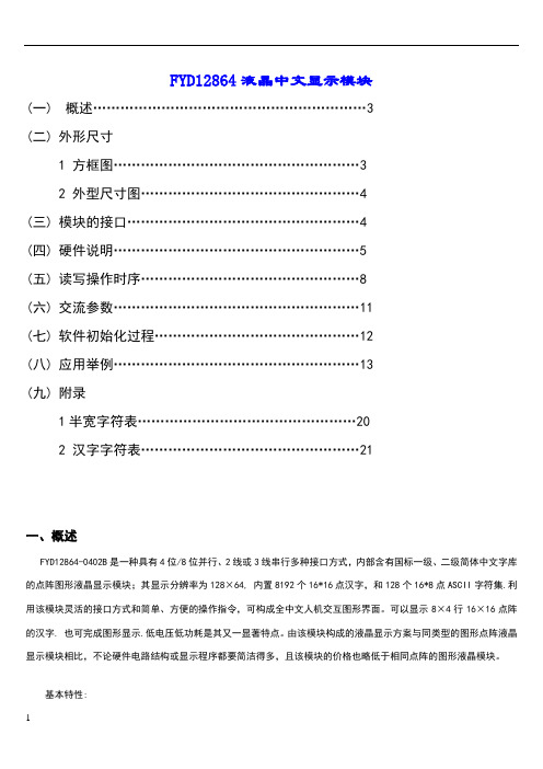
FYD12864液晶中文显示模块(一)概述 (3)(二)外形尺寸1 方框图 (3)2 外型尺寸图 (4)(三)模块的接口 (4)(四)硬件说明 (5)(五)读写操作时序 (8)(六)交流参数 (11)(七)软件初始化过程 (12)(八)应用举例 (13)(九)附录1半宽字符表 (20)2 汉字字符表 (21)一、概述FYD12864-0402B是一种具有4位/8位并行、2线或3线串行多种接口方式,内部含有国标一级、二级简体中文字库的点阵图形液晶显示模块;其显示分辨率为128×64, 内置8192个16*16点汉字,和128个16*8点ASCII字符集.利用该模块灵活的接口方式和简单、方便的操作指令,可构成全中文人机交互图形界面。
可以显示8×4行16×16点阵的汉字. 也可完成图形显示.低电压低功耗是其又一显著特点。
由该模块构成的液晶显示方案与同类型的图形点阵液晶显示模块相比,不论硬件电路结构或显示程序都要简洁得多,且该模块的价格也略低于相同点阵的图形液晶模块。
基本特性:低电源电压(VDD:++)显示分辨率:128×64点内置汉字字库,提供8192个16×16点阵汉字(简繁体可选)内置 128个16×8点阵字符2MHZ时钟频率显示方式:STN、半透、正显驱动方式:1/32DUTY,1/5BIAS视角方向:6点背光方式:侧部高亮白色LED,功耗仅为普通LED的1/5—1/10通讯方式:串行、并口可选内置DC-DC转换电路,无需外加负压无需片选信号,简化软件设计工作温度: 0℃ - +55℃ ,存储温度: -20℃ - +60℃二、方框图3、外形尺寸图三、模块接口说明*注释1:如在实际应用中仅使用串口通讯模式,可将PSB接固定低电平,也可以将模块上的J8和“GND”用焊锡短接。
*注释2:模块内部接有上电复位电路,因此在不需要经常复位的场合可将该端悬空。
- 1、下载文档前请自行甄别文档内容的完整性,平台不提供额外的编辑、内容补充、找答案等附加服务。
- 2、"仅部分预览"的文档,不可在线预览部分如存在完整性等问题,可反馈申请退款(可完整预览的文档不适用该条件!)。
- 3、如文档侵犯您的权益,请联系客服反馈,我们会尽快为您处理(人工客服工作时间:9:00-18:30)。
一、概述:YLF320240A-GB中文字库液晶显示模块是一个中英文文字与绘图模式的点矩阵液晶显示模块,内建512KByte 的ROM 字形码,可以显示中文字型、数字符号、英日欧文等字母,并且内建双图层(Two Page)的显示内存。
在文字模式中,可接收标准中文文字内码直接显示中文,而不需要进入绘图模式以绘图方式描绘中文,可以节省许多微处理器时间,提升液晶显示中文之处理效率。
此液晶显示模块除了支持8080/6800 系列之MCU 外,也提供4-Bit 或8-Bit 的数据总线接口。
此液晶显示模块支持320×240点阵的LCD 面板,当字型为16×16 时,可秀出20(列)×15(行)个全型中文字,在字型方面有多种字号可供选择使用,如16×16、32×32、48×48、64×64 及不同比例的混合显示模式,同时内建的512Byte SRAM 提供了自行造字的功能。
支持文字与绘图两种混和显示模式 支持2 Page 显示模式(And, Or, Nor, Xor),内建两个4.8K / 9.6 K Byte 的显示RAM (Display Data RAM),并且可做成4 阶的显示效果。
内建512KByte ROM,控制IC 分带繁体字库IC 和带简体字库IC,其中标准繁体中文BIG5 码,包含13,094 个常用与次常用字型、408 个特殊字与两组ASCII CODE,简体字库储存7602 个标准GB 码的简体中文。
提供全角(16×16)与半角(8×16)文字显示模式 支持4/8 位之6800/8080 MCU 接口;带光标、反白、闪烁功能,且光标高度与宽度可调;支持屏幕水平卷动及垂直卷动功能;内建512Byte SRAM 可自行造字;提供中/英文文字对齐功能;显示字型可放大到32×32、48×48 或64×64,以及混合显示模式;支持可将字型由ROM 直接读出使用;内建粗体字形与行距设定。
※注意:客户在使用YLF320240A-GB模块时,可选择中文字库控制器或图形点阵控制器,但需出厂前设定。
此说明书只对中文字库控制器(简体中文)。
二、模块结构图:第 1 页,共 84 页三、主要参数:项 目 参 考 值 逻辑工作电压(Vdd) +4.5~+5.5VLCD驱动电压(Vdd-Vo) 20.5V工作温度(Ta) -20~+70℃(宽温)储存温度(Tsto) -30~+80℃(宽温)工作电流(背光除外) 70.0mA(max)四、接口引脚说明:(以下接口定义为中文字库控制器)引脚名称方向说明1 VSS -- 电源负端(0V)。
2 VDD -- 电源正端(+5V)。
3 V0 -- LCD驱动电压(外接可调电阻,调节对比度)4 RS(A0) I H:存取DDRAM;L:存取缓存器。
5 /WR(R/W) I 6800系列:读/写脚(R/W);H:读,L:写。
8080系列:写入脚(/WR),低有效。
6 /RD(EN) I 6800系列:使能脚(EN),高有效。
8080系列:读入脚(/RD),低有效。
7~14 DB0~DB7 I/O 负责在LCM及微处理器之间做资料料传送与接收。
当MCU为4位模式下,高位DB[7..4]需浮接。
15 /CS I 当/CS为Lo时,模块处于致能,可接受指令,反之不可接收指令。
16 /RESET I 复位信号,低有效。
17 VEE -- LCD驱动负压电源输出。
18 BUSY O 用以回应模块内部的执行使用状况,可设成高或低电平触发。
19 INT O 用以回应模块内部的中断状况,可设成高或低电平触发。
20 LED+ -- 背光电源正端(+5V)。
21 LED- -- 背光电源负端(0V)。
说明:1)DB选择点与1处(VDD)连接时,为8Bit;与2处(VSS)连接时,为4Bit。
2)MI选择点与1处(VDD)连接时,为6800系列;与2处(VSS)连接时,为8080系列。
3)背光源使用CCFL/EL时,需逆变器进行升压。
接口第20、21脚不接。
第 2 页,共 84 页五、微控制器(MPU)说明:1、8080 系列MPU说明:YLF320240A-GB 与8080 兼容系列的MPU 接口示意图,此时LCM 将只接受与8080 系列兼容的MPU 所传送出来的控制信号。
图5.1:8080 (4/8-bit) MPU 与LCM的界面图图5.2是8080系列MPU与LCM间的系统时序图,在LCM的定义中,RS 为 “L” 时,是表示对缓存器下命令,也就是对LCM的缓存器进行读写的动作(Register Access Cycle),而RS 为 “H” 时是表示对Display RAM 进行Data 读写的动作(Data Access Cycle)。
不论是8080 或6800, “RS” Pin 通常接到MPU 的Address Pin “A0”,8080 系列MPU 与6800 最大的不同是Read、Write 的控制信号是分开的,RD 为Low 时是进行读取动作,WR 为Low 时是进行写入动作,至于读写的目的地则由RS 决定。
下图5.2表示如果是对缓存器进行读取动作,MPU 必须透过数据总线先送出缓存器的地址,然后才能在数据总线上读取缓存器的数据,如果是对缓存器进行写入动作,MPU 必须透过数据总线先送出缓存器的地址,然后再送出要写入的数据。
当8088 MPU 对LCM Display RAM 进行数据的读取动作,MPU 能直接在数据总线上读取Display RAM 的数据,如果8088 MPU 对Display RAM 进行数据的写入动作,MPU 则直接在数据总线上送出要写入的数据。
图5.2:8-Bit 8080 MCU 对LCM缓存器/DATA 进行读取/写入动作第 3 页,共 84 页2、6800系列MPU说明:图5.3 是LCM 与6800 兼容系列的MPU 接口示意图,此时LCM 将只接受6800 系列兼容的MPU 所传送出来的控制时序。
图5.3:6800 (8-bit) MPU 与LCM的界面图6800 系列MPU Read、Write 的控制信号是同一根Pin,R/W 为High 时是进行读取动作,R/W 为Low 时是进行写入动作,而EN 则是确定读写的动作是否有效(Enable),至于读写的目的地仍由RS 决定。
此LCM无法同时接受6800 及8080 的控制信号,因此在MPU 的接口上,某些脚位上会因为使用者选择不同的MPU 而有不同的定义,例如脚位/RD(EN),当使用者选择的MPU 接口为8080 时是定义成/RD,而选择6800 MPU 时是定义为EN。
而脚位/WR(R/W),当使用者选择的MPU 接口为8080时是定义成/WR,而选择6800 MPU 时是定义为R/W。
下面图5.4表示如果是6800 MPU 对LCM缓存器进行读取动作,MPU 必须透过数据总线先送出缓存器的地址,然后才能在数据总线上读取缓存器的数据,如果是对缓存器进行写入动作,MPU 必须透过数据总线先送出缓存器的地址,然后再送出要写入的数据。
当6800 对LCM Display RAM进行数据的读取动作,MPU 能直接在数据第 4 页,共 84 页第 5 页,共 84 页总线上读取Display RAM 的数据,如果6800 MPU 对Display RAM 进行数据的写入动作,则MPU 直接在数据总线上送出要写入的数据。
对于6800 MPU 的接口,LCM只提供8Bit 的传输功能,而对于8080 MPU 的接口,LCM 提供4Bit 或8Bit 的传输功能。
图5.4:8-bit 6800 MPU 对LCM 缓存器/Data 进行读取/写入动作3、4Bit/8Bit 的MPU 接口:此中文字库液晶显示模块除了支持8080 和6800 两大系列兼容的MPU 接口外,也可以设定MPU 上的数据总线接口是4-Bit 或是8-Bit,出厂时默认8-Bit 接口。
因为控制IC 内部的缓存器大多是8-Bit 的架构,因此如果使用4-Bit 的数据总线接口,MCPU 将会花较多的周期(Cycle)去存取内部的缓存器。
当选择4-bit MCU 作传输模式时,中文字库液晶显示模块的MCU 接口只有用到数据总线的DB3~DB0,而没有用到的DB7~DB4 则不必理会(当成NC Pin),同时每一个八位的指令或资料将被分为两个Nibble (4-Bit) 依序透过数据总线的DB3~DB0 进行传送,第一次先透过总线(DB3~DB0) 传送资料的较高位Bit[7..4],第二次再透过总线(DB3~DB0)传送资料的较低位Bit[3..0]。
六、中文字型ROM:此中文字库液晶显示模块内建有512KByte 的16×16 中文显示字型ROM(Font ROM) 与8×16 的ASCII 半型字型。
除了内建的8×16 和16×16 的字号外,还提供字型放大的功能,可利用REG[F1h]的设定,将显示字号放大到32×32、48×48 或64×64。
控制IC 分带繁体字库IC 和带简体字库IC,其中标准繁体中文BIG5 码,包含13,094 个常用与次常用字型、408 个特殊字与两组ASCII CODE;简体字库储存7602 个标准GB 码的简体中文。
缓存器[F0h]是用来设定与字型ROM 相关的功能,当使用带繁体字库IC 时,必须将Bit[5..4]设成“01” 才能正确显示繁体字型,当使用带简体字库IC 时,必须将Bit[5..4]设成“10” 才能正确显示简体字型。
注意:中文内码不论是GB 或BIG5 码都是由两个Byte 组成,但是英文及一些符号ASCII 码只由一个Byte 组成(00h~FFh),通常LCM 将送到Display RAM 的Data(00h~9Fh)视为ASCII码,也就半角文字(8×16),大于等于 “A0h”的视为全角码(如繁简中文)的高位,必须再送一次低位内码,才能显示全角字型。
如果使用者有用到A0h~FFh 的ASCII 码,则MPU 在送Data(ASCII 码)到Display RAM 之前必须将缓存器[F0h]的Bit2 设成 “1” 。
第 6 页,共 84 页七、功能应用介绍:1、文字模式设定:1) 文字显示:YLF320240A-GB LCM的文字模式可以支持全角(中文或英文)及半角(英文)的显示,全角文字是以16×16 的点矩阵组成,半角文字是8×16 的点矩阵组成,如图7.1所示。