多路数据采集与控制系统
文献翻译-多路数据采集与分析系统的设计及应用

附录五中英文资料Multi-channel data collection and analysisof the design and applicationAbstract:The Paper mainly introduces a multichannel data acquisition and analysis system composed of one PC and one measuring instrument. The system can test eight products parallelly. It reduces the test cost and improves work efficiency. The paper also gives the hardware structure and software flow diagr am of the system. The application in the gyro test is also introduced briefly.Key words:communication prot;data acquisition; gyro; testWith the development of computer technology and the digital measuring instrument, usually by computer and measuring instruments to communicate with each other in real-time data collection and use of computer powerful computing capability to conduct the analysis of the data processing. Particularly in the large volume of data, measuring the length of time occasions, such as the Gyro-tilt test, using computer for automatic control of measuring instruments, automatic data acquisition and analysis it is particularly important, can save a lot of manpower and material resources to improve work efficiency, reduce costs , The conventional method of testing is usually a measuring instrument at the same time can only test a product, namely a computer and a measuring instrument test system can only be composed of serial testing. To test multiple products at the same time, they need multiple systems, testing products in large volume, low efficiency, such as the composition of several sets of test system, an increase of cost. First on a machine with a PC and a measuring instrument consisting of 8-way data collection and analysissystem, which can carry out multiple sets of product testing, at no additional cost on the basis of a computer give full play to the advantages of automatic test, Improve work efficiency.1 PrincipleThe system hardware and software system. A PC through a RS232 port and a measuring instrument connected, PC-parallel port (LPT) and an 8-way channel selector attached to a 8-way connector will channel selector were connected with a number of test products.The working principle as shown in Figure 1. The course of testing, computer through the parallel port 8-way control channel selection, were open different channels, each channel for data transmission by choosing to measuring instruments, measuring instruments through the RS232 port to the computer data sent to save, A complete cycle of all channels of data collection, and this has also tested a number of product features.Figure 1 system block diagram of workThroughout the course of testing, all the control operations have completed the software automatically, without human intervention.2 hardware designThe system is mainly to use the computer onboard RS232 communication ports and digital measuring instrument of communication port connecting communications, re-use LPT parallel port on a 8-way channel selector for access control. 8-way channel of choice for an 8-elected one of analog switches and related circuit, the control signals from the computer's parallel port to provide and meet shown in table 1.Table1 The relation between channel selection and port output8-way channel selector industry can use the SCM, subject to additional controls, select RS232 serial port as data transmission, because the RS232 port is the computer and measuring instruments on the standard configuration, communicate with each other without additional hardware , Easy to use. In addition, a serial communication-only a bit, with only a standard data-voltage potential, hence more difficult in data errors. In a parallel port to transfer data 8-bit, data transmission speed, but the data vulnerable to interference. Transmission distance in a shorter amount of data transmission larger circumstances, may be parallel port (such as GPIB, LPT, etc.) to communicate. In addition, since LPT parallel port may signal transmission, channel selection is suitable for the control port.System in the course of work, good access control modules and data acquisition module synchronization is particularly important because different channels of datastorage needs of the corresponding data buffer pool, which is controlled by software.3 software designThe whole system software design is the most important part. Software system from the bottom of the communication protocol can be divided into functional three-tier module and user interface. Software design in the use of multi-threaded Windows technology, the technology for data collection procedures can effectively accelerate the reaction time and increase the efficiency of implementation. The procedures used in a separate thread for data collection, so the guaranteed maximum energy collection of real-time; using another thread at the same time data processing, such procedures to avoid a single-threaded the same time only the implementation of a functional deficiencies. Especially when the amount of data collection, data processing task, using multi-threaded technology will greatly improve the efficiency of the system as a whole.3.1 Data Acquisition ModuleData acquisition modules to eight channels of data in a cycle of all the acquisition to the computer, and save the channel, and the corresponding data in the buffer. Its procedures diagram shown in Figure 2.Fig 2 Flow diagram of data acquisitionAt the beginning of procedures, with the choice of control and store data buffer at the same time to switch to the same channel, 8-way data collection cycle and command judgement, in the end not received orders, has recycling collection to do.Multi-channel data acquisition process the data vulnerable to interference, especially in the fast-channel switching, the data vulnerable to fluctuations, as shown in Figure 3. At this time if the data collection, will be collecting the wrong data, the need to add some software algorithms to prevent this from happening. If we develop the automated data tracking algorithm to automatically track each channel data to determine whether the channel in a stable state, and only the stability of dataacquisition, the volatility of other data. In addition, the software can also add some filtering algorithm (such as limiting filter, etc.) to filter out man-made interference or other factors caused by the mutation data. Limiting filter for(1)Figure 3 channel switching, the data volatilityWhen the new collected data and the data before a difference to the absolute value of more than one set of values that the data is invalid, and the previous data from the current data.3.2 Data Analysis ModuleIn the data analysis module can be added if the algorithm analysis, graphics display and print output, and other useful features, such as gyroscopes and stability in the standard deviation algorithm can function in the course of testing real-time calculation of zero stability, and through chart shows. Zero stability calculation formula as follows:(2)According to first-(2) to prepare an algorithm function, and then call in the analysis module. Analysis module diagram of the procedure shown in Figure 4.Figure 4 data analysis process flow chartBecause the system uses multi-threaded technology, in the cycle of operation and will not affect the acquisition module's operation. The module also in its algorithm in the function of any expansion, forming a algorithm to adapt to different procedures for data analysis.In addition, software design, a friendly user interface is necessary in the process of the functions from the package, through a unified interface to users, to reduce operating difficulties and enhance efficiency.4 system test resultsFigure 5 to 8 in the analysis of data acquisition systems, at the same time two three-axis gyro and a single axis gyroscope total of seven road test data of thesituation. Its precise data collection, data analysis can be conducted at the same time, and through real-time charts, user-friendly, easy to operate.Figure 5 8 Data Collection and Analysis System5 ConclusionMulti-channel data acquisition and analysis system for the hardware requirements simple, easy to set up, can be applied to various tests occasions, it can also test multiple products, thereby reducing the cost and enhance efficiency. As a result of a multi-threaded technology, the speed of data acquisition systems and hardware only (instrument) and the response speed of the speed of Communication. With the collection and analysis software algorithm has nothing to do.PAD programming tools can be used to develop a data collection, data analysis, graphics display and print output, and other powerful features and friendly user interface of our software. Software modular design and easy to carry out expansion, according to different algorithm for data analysis at the request of upgrades, and hardware can remain the same. The system give full play to the use of computers and measuring instruments of mutual communication, automation and test advantage.多路数据采集与分析系统的设计及应用摘要:介绍了用一台PC机和一台测量仪表组成的8路数据采集与分析系统。
CPLD在远程多路数据采集系统中的应用

CPLD 在远程多路数据采集系统中的应用 摘要采用语言和图形输入设计方法,给出了用在远程多路数据采集系 统中实现地址译码、串口扩展、模块测试、模数转换以及高位数据处理等 功能的具体方法,同时简要介绍了远程多路数据采集系统的工作原理及软、 硬件框架。
关键词;单片机;译码;-232;;7256208CPLDComplexP rogrammableLogicDevice 件是在传统的PAL、GAL基础上发展起来的。
目前, CPLD已在通讯、 DSP及微机系统中有着非常广泛的应用, 它不仅可使设计的产品小型化、集成化和稳定可靠,而且还具有在系统或 在芯片直接编程的能力,从而使电子系统的设计、开发、更新与维护变得 更为方便,更便于装配和批量生产。
因此,利用CPLD可大大缩短设计周期,减少设计费用,降低设计 风险。
远程多路数据采集系统,不但需要较多的片选信号,而且模块测试所 占用的I/O口资源也较多,用一般的芯片较难实现,而用CPLD/F PGA则不但可以较好地实现其功能,而且还可大大提高设计能力和设计 效率。
1 复杂可编程逻辑器系统组成思路本远程多路数据采集系统以Altera公司700 0S系列CPLD产品中的EPM7256SQC208-10为控制 核心,并由A/D模拟量采集模块、DI数字量采集模块、D/A模拟量 输出模块、DO数字量输出模块、MCU模块、电源模块及I/O接口模 块组成,其系统组成原理图如图1所示。
图中,MCU模块主要由CAN总线模块、RS-485模块、RS -232模块、时钟和复位模块、CPLD模块等组成,MCU模块的电 路原理图如图2所示。
该远程多路数据采集系统的I/O接口板共有14个插槽,其中12 个插槽可实现A/D模块、D/A模块、DI模块、DO模块等四种模块 的任意配置。
因此,单个数据采集系统最大可采集192路模拟量或192路数字 量,也可以提供最大96路模拟量输出或192路数字量输出。
数据采集系统(第二组)

数据采集系统的设计姓名:专业:指导老师:学号:前言数据采集是从一个或多个信号获取对象信息的过程。
随着微型计算机技术的飞速发展和普及,数据采集监测已成为日益重要的检测技术,广泛应用于工农业等需要同时监控温度、湿度和压力等场合。
数据采集是工业控制等系统中的重要环节,通常采用一些功能相对独立的单片机系统来实现,作为测控系统不可缺少的部分,数据采集的性能特点直接影响到整个系统。
本实验采用89C51系列单片机,89C51系列单片机基于简化的嵌入式控制系统结构,具有体积小、重量轻,具有很强的灵活性,并采用AD0809模数转换芯片,具有很高的稳定性,且节约成本。
(一)、数据采集系统的基本介绍1.1 数据采集系统的简介数据采集系统一般包括模拟信号的输入输出通道和数字信号的输入输出通道。
数据采集系统的输入又称为数据的收集;数据采集系统的输出又称为数据的分配。
1.2数据采集系统的分类数据采集系统的结构形式多种多样,用途和功能也各不相同,常见的分类方法有以下几种:根据数据采集系统的功能分类:数据收集和数据分配;根据数据采集系统适应环境分类:隔离型和非隔离型,集中式和分布式,高速、中速和低速型;根据数据采集系统的控制功能分类:智能化数据采集系统,非智能化数据采集系统;根据模拟信号的性质分类:电压信号和电流信号,高电平信号和低电平信号,单端输入(SE)和差动输入(DE),单极性和双极性;根据信号通道的结构方式分类:单通道方式,多通道方式。
1.3数据采集系统的基本功能数据采集系统的任务,具体地说,就是采集传感器输出的模拟信号并转换成计算机能识别的数字信号,然后送入计算机,根据不同的需要由计算机进行相应的计算和处理,得出所需的数据。
与此同时,将计算得到的数根进行显示和打印,以便实现对某些物理量的监视。
1.4数据采集系统的结构形式从硬件力向来看,白前数据采集系统的结构形式主要有两种:一种是微型计算机数据采集系统;另一种是集散型数据采集系统。
第8章 数据采集控制系统的设计

ST3
ALE<='0' START<='0' OE<='0' LOCK<='0' CEN<='0'
图8.4 ADC0809工作时的状态转换图
第8章
数据采集控制系统的设计与分析
2.转换后数据的BCD码转换处理 表8.1是在ADC0809的基准电压(Vref)为5.12 V时, 模拟输入电压与输出电压的对应关系表,其中最小电 压准位是5/28=5/256=0.2 V。 这样,当由ADC0809的D[7..0]收到的数据信号是
转换为8位数字量DATA。
第8章
数据采集控制系统的设计与分析
(2) 输入数据与通过预置按键输入数据采集控制器 内的标准数据相减,求得带极性位的差值±ΔU(数字 量);差值之绝对值送至DAC0832转换为ΔU,它和特 定的极性判别电路共同输出±ΔU。 (3) 数据采集和处理均在数据采集系统控制器的管
SIGNAL V: STD_LOGIC_VECTOR(7 DOWNTO 0);
SIGNAL HB,LB: STD_LOGIC_VECTOR(11 DOWNTO 0); SIGNAL C30,C74,C118: STD_LOGIC;
SIGNAL TEMPA , TEMPB , TEMPC: STD_LOGIC_VECTOR(4
第8章
数据采集控制系统的设计与分析
图8.2 数据采集系统总体组成原理图
第8章
数据采集控制系统的设计与分析
8.2.2 A/D转换控制模块ADZHKZ的设计 1.ADC0809模数转换的控制 ADC0809是CMOS的8位A/D转换器,片内有8路模 拟开关,可控制8个模拟量中的一个进入转换器中。 ADC0809的分辨率为8位,转换时间约100 μs,含锁存
智能仪器第7章 数据采集系统
20nA
20nA 20nA
40ns
40ns\ 40ns
40us
40us 40us
双向三路 单选一
双向单十 六选一 双向双八 选一
±7.5V
±7.5V ±7.5V
≤30mA
≤30mA ≤30mA
7.4 数据采集系统设计
1 系统设计考虑的因素 数据采集系统设计要根据测试对象及系统的技术指标,主要考虑下列因素。 1.1 输入信号的特征 在输入信号的特性方面主要考虑:信号的数量,信号的特点,是模拟量还是数字 量,信号的强弱及动态范围,信号的输入方式,信号的频带宽度,信号是周期信号还 是瞬态信号,信号中的噪声及其共模电压大小,信号源的阻抗等等。 1.2 对数据采集系统性能的要求 1.2.1 系统的通过速率 系统的通过速率通常又称为系统速度、传输速率、采样速率或吞吐率,是指单位 时间内系统对模拟信号的采集次数。 1.2.2 系统的分辨力 系统的分辨力是指数据采集系统可以分辨的输入信号最小变化量。 1.2.3 系统的准确度 系统准确度是指当系统工作在额定通过速率下,系统采集的数值和实际值之间的 接近程度,它表明系统误差的总和。 1.3 接口特性 接口特性包括采样数据的输出形式,数据的编码格式,与什么数据总线相接等。
2 模拟电路的误差
2.1 模拟开关导通电阻RON的误差 模拟开关存在一定的导通电阻,信号经过模拟开关会产生压降。模拟开关 的负载一般是采样/保持器或放大器。显然,开关的导通电阻越大,信号在开 关上的压降越大,产生的误差也越大。 2.2 多路模拟开关泄漏电流IS引起的误差 如果信号源的内阻小,泄漏电流影响不大,有时可以忽略。如果信号源内 阻很大,而且信号源输出的信号电平较低,就需要考虑模拟开关的泄漏电流的 影响。一般希望泄漏电流越小越好。 2.3 采样保持器衰减率引起的误差 如果衰减率大,在A/D转换期间保持电压减小,影响测量准确度。一般选 择漏电流小的聚四氟乙烯等优质电容,可以使衰减率引起的误差忽略不计。 2.4 放大器的误差 数据采集系统往往需要是用放大器对信号进行放大并规一化。放大器是 系统的主要误差来源之一。其中有放大器的非线性误差、增益误差,零位误差 等。在计算系统误差时必须把它们考虑进去。
基于LabVIEW串口通信的多路数据采集系统设计
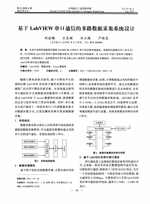
2 数 据 采集模块
串行通信是工业现场仪器或设备常用的通信方 式 , 是将 一 条 信 号 的各 位 数 据 按 顺 序 逐 位 传 送 。 它
计算 机 串行 通信 ( 称 串 口 ) 用 R 22协议 , 许 简 采 S3 允
一
基 于 单 片机 的无 线数 据采 集 , 主要 完 成对 实 际
统采用高速 、 低功耗单片机和无线收发芯片进行构
建下 位 节 点 的无 线 数 据 采 集 前 端 。 n 2 0 RF 4 1是 单 片 2 4 Hz . GH .G ~2 5 z收发 芯 片 , 置 频 率 合成 器 、 内
信为用户提供 了一种使用 串行 口代替数 据采集 卡
的数 据 采 集 方 式 , 以更 低 廉 的 价 格 实 现 多 路 数 据
0 al等 。与 S rc e QL兼 容 , 使 用 s 不 QL语 句 就 可 以 实现数 据 库 记 录 的查 询 、 加 、 改 以及 删 除 等 操 添 修 作 , 户 可 以完全 不需 要学 习 S 用 QL语 法 。
Lb Q a S L利用 Mi oot O对 象 和 S c sf AD r QL语 言
CoeC n ls o n四个 控 件 以及 简 单 的 S QL语 句 将 采 集
并 处理 完 的数据 保存 到数 据库 中。
6 L b l\ 中数据 的处 理 a VE/ \ /
过使 用 单 片 机 进 行 数 据 采 集 , 温 度 与 湿 度 用 十 将 六进 制 的形 式 记 录 在 单 片 机 内 , 后 通 过 串 口将 然
口通信 时 , 首先 要对 串 口进行 初始 化 和配 置 , 可 以 这
5 L b E 与 A c s 数 据库 的 连接 a VI W ces
基于PIC单片机的多路数据采集系统
收稿日期:2007Ο11Ο23;修改稿收到日期:2008Ο03Ο07作者简介:芦艳(1982—),女,甘肃兰州人,硕士研究生.主要研究方向为电路理论及应用.3通讯联系人,副教授,硕士研究生导师Ο@11基于PIC 单片机的多路数据采集系统芦 艳,裴 东3,梁西银,吕恩胜(西北师范大学物理与电子工程学院,甘肃兰州 730070)摘 要:提出了一种以P IC16F877单片机作为核心器件的多路数据采集系统的设计和实现方法.该系统利用PIC 单片机自身具有的8路10位A/D 转换模块及多种输入输出端口,以最小的硬件开销,实现了对8路数据的循环采集、固定通道采集、实时处理及显示的功能.具有电路简单、精度高、功耗低、抗干扰能力强、通用性强的特点.关键词:多路数据采集系统;PIC 单片机;A/D 转换;实时控制中图分类号:TP 274+12 文献标识码:A 文章编号:10012988Ⅹ(2008)0620050204Multi Οchannel data acquisition system based on microchip PICLU Yan ,P EI Dong ,L IAN G X i Οyin ,L ΒEn Οsheng(College of Physics a nd Electronic Engineering ,Nort hwest Normal Univer sity ,Lanzhou 730070,G ansu ,China )Abstract :Thi s articl e i nt roduces t he designi ng met hod of t he m ult i Οchannel data acqui si tion syst em wit h P IC16F877as it s kernel p roce ssor chip.Ba se d on t he eight channel 10bi t A/D and various I/O port s of t he microchip PIC ,t hi s system can realize coll ecti ng dat a of eight Οcha nnel circularly or coll ecti ng dat a of fi xed cha nnel as well a s p rocessi ng and di splayi ng t he dat a in real Οt ime at t he lowe st ha rdware cost.The system has t hese me rit s such as simpl e ha rdware ,higher precision a nd lower power.And it ha s t he abilit y of st rong a nti Οinterf ere nce and good ext ensi bili t y.K ey w or ds :mul ti Οchannel dat a acqui si tion syste m ;microchip PIC ;A/D co nversion ;real Οti me cont rol 数据采集是数字系统必不可少的组成部分.作为测控系统中重要的一环,数据采集的实时性和可靠性是工业控制系统的重要因素[1].现有的基于单片机的多路数据采集系统一般都通过外加A/D转换器及多路模拟开关等芯片来实现[2Ο5].这样整个系统的外围电路复杂、体积大,布线繁杂,性价比及可靠性随之降低.为此笔者选择了具有运行速度快、功耗低、性价比高、功能强等突出优点,且内部自带8路10位A/D 转换器的P IC16F877单片机作为设计核心,实现了对8路数据的采集及初步处理;并可进行现场数据显示、键盘控制及系统报警等功能.由于系统设计方案选用了功能强大的P IC 单片机,因此对数据的处理能力较强;且其内部已经集成了多通道的A/D 转换器,只需通过RA 0~RA 3、RA 5、R E 0~RE 2引脚即可输入8路模拟电压,从而完成对8路数据的采集、处理.减少了外围电路,有效地提高了数据采集系统的集成度及性价比,并大幅度降低了功耗及硬件开销.1 系统硬件设计系统原理框图如图1所示.图1 系统原理框图Fig 1Bloc k diagram of the syste m如图2所示,单片机外围电路结构主要包括传感器与单片机的连接电路、数码显示、键盘电路三大部分.单片机时钟电路由4MHz 的无源晶振接两个电容[6],结合单片机内部的振荡电路构成..E mail :peidong nwnu edu cn 2008 No 16 Multi Οc hannel data acquisition system base d on mic rochip P IC图2 基于PIC 单片机的多路数据采集系统硬件电路图Fig 2Har dware cir cuit of the system111 传感器与单片机的连接电路本电路在设计阶段不使用具体的传感器,而是用电位器分压模拟,如图3所示.图3 传感器连接电路Fig 3Connecting circuit of se nsor在系统调试阶段利用输入端的电位器可对来自直流源的5V 直流电压进行直流分压,产生0~5V (本系统PIC 内部A/D 所能接受的电压范围)的直流电压分别加于0通道至7通道,进行个通道的数据采集(若需测量高于5V 的信号电压,输入端应接衰减电路).为了能对有正负极性的外信号进行数据采集,采用了正端输入负反馈运放作跟随器,并在其输出端作电平变换.这样就将本系统输入信号的电压范围扩展到-5~5V.112 数据显示及键盘输入数据显示共用6个L ED 数码管,其中1个用于显示通道号0~7;1个用于显示数据符号位;其余4个为数据显示位.数码管与CPU 间的接口用6片8位串行输入、并行输出电路74L S164,一方面传输数据,另一方面驱动数码管.74LS164为普通的TTL 电路,接一片74LS164可扩展一个8位并行口,用以连接一位八段数码管L ED.74LS164输出(Q 0~Q 7)作为L ED 的段驱动时,只能连接共阳极数码管.多片74L S164连接时,低位的Q 7要与高位的A 、B 端相连,这样才能实现多片移位.由此带来的好处是大量节省了CPU 的端口资源.系统中只用了RD 7、RD 6、RD 5这3个引脚.本系统直接利用PIC 的引脚作为键盘行、列线,实现行列式4×4键盘.键盘具有数据采集方式选择及固定通道采集方式时通道号输入等功能158.2 系统软件设计本系统的系统软件框图如图4所示.主要用于系统自检、键盘扫描、A/D 转换及数据显示功能的实现.图4 系统软件框图Fig 4Block dia gra m of system sof tware整个系统软件由主程序和4个子程序组成.主程序进行数据初始化设置,在系统通电后先进行系统自检.子程序包括设置八段数码显示表格、键盘扫描、延时及A/D 转换.键盘扫描采用中断方式,用扫描法识别被按下键.8路A/D 采集方式由键盘进行选择,即循环采集和固定通道采集,系统默认的采集方式为8通道循环采集.系统采用中断方式来查询A/D 转换是否结束,若查询到结束信号则将数据进行B CD 码转换,以完成数据的各位显示.显示的过程是先通过查表,得到正确的显示代码,然后将此代码串行传输给显示电路.211 多通道A /D 转换的实现PIC16F877单片机内部集成的A/D 转换部件可以在休眠状态下进行A/D 转换,可由A/D 转换结束中断激活单片机.采用这种工作方式,在A/D 采样和转换时间内,单片机主频关闭,干扰小,既提高了A/D 转换的精度,又减少了功耗.由于此内部转换模块可支持8个通道的模拟输入,所以实现单路或多路A/D 转换的功能极为方便.哪一路进行A/D 转换,可由软件实现(由于篇幅所限程序源代码略).A/D 流程图如图5所示.图5 A/D 转换流程图Fig 5A/D conver sion f low chart212 数字滤波考虑到单片机通过模拟量输入通道所采集的数据中常常混杂有干扰,需要数字滤波予以滤除,所以本设计采用了对周期性的干扰及热噪声产生的干扰有良好抑制作用的平均值滤波[6].本设计在t =200μs 时间内,连续对模拟输入引脚上的电压采样10次.以10次采样值的平均值作为采样结果,参与程序运算.在AD 采样中断子程序中直接 2008 No16 MultiΟc hannel data acquisition system base d on mic rochip P IC 求取10次采样值的和,平均值可以在主程序中需要用到采样值的地方求取.10次采样结果的和保存在AD H、ADL两个寄存器中.TEMP寄存器用于控制AD采样次数,在每一次AD采样周期开始时,COUN T寄存器的值为10.3 结语上述数据采集系统在设计方面充分利用PIC 单片机自身的软硬件资源,大大降低了软硬件设计的复杂度和整个系统开发、维护的成本,提高了系统的可靠性.相比其它实现方案,具有使用器件少、节约成本、调试方便等特点,很好地满足了数据采集系统对实时性、同步性、高速性的要求.此系统在应用时配上不同的传感器及相应的处理电路,稍加改动,便可在许多领域得到广泛应用,因而具有较高的实用性和开发价值.参考文献:[1] 冉策方,周国忠.基于Compact PCI总线的数据采集系统设计[J].微计算机信息,2006,22(12Ο2):44Ο46.[2] 刘丽娜,安 颖.基于单片机的多通道数据采集板的设计[J].河北能源职业技术学院学报,2005(1):66Ο67.[3] 杨 博,李宛洲.基于单片机的新型多路数据采集系统[J].仪表技术与传感器,2006(11):45Ο46. [4] 李雯霏,刘增力,杨长茂.基于16位单片机80C196的智能化高速数据采集系统设计[J].河南科技大学学报:自然科学版,2007,28(3):43Ο45.[5] 孙沁梅,容太平.多路数据循环采集系统设计[J].电子世界,2005(5):25Ο26.[6] 求是科技.PIC单片机典型模块设计实例导航[M].北京:人民邮电出版社,2005.(责任编辑 孙晓玲)(上接第40页)[9] DO H H,SIGR IS T M,C HAO B K,et al.Phe nome n ological theor y of superconductivity andmagnetism in Ho1-x Dy x Ni2B2C[J].Phys Rev L ett,1999,83(25):5350Ο5353.[10] AS KERZADE I N,TANATAR B.Angerdepende nce of uppe r critical f ield in twoΟba nd GΟLt heo ry[J].Physic C,2007,459:56Ο61.[11] AS KERZADE I N.GΟL theo ry for twoΟba nd sΟwavesuperconductoes:application to no nΟmagneticb orocar bides L uNi2B2C Y Ni2B2C and ma gnesiumdiboride MgB2[J].Physic C,2003,397:99Ο111.[12] AS KERZADE I N,GENCER A,GΒCLΒN.Ont he G inzburgΟLanda u analysis of the uppe r criticalfield H c2in MgB2[J].S upercon d Sci Technol,2002,15:L13ΟL16.[13] AS KERZADE I N,GENCER A.Londonpenet ration dept hλ(T)in twoΟband G inz burgΟLa ndaut heo ry:applica tio n to MgB2[J].S olid St ateCommunica tions,2002,123:63Ο67.[14] C H EN Xia nΟhui,XUE Y Y,M EN G R L,et al.Penetr ation dept h a nd a nisotropy in MgB2[J].P hysRev B,2001,64(17):172501Ο172504.(责任编辑 孙晓玲)35。
基于AT89S52多路数据采集系统的设计
2 多路 采集 系统 的硬 件设计
整 个硬件系统 是 以单 片机 A 8 S2作 为 主控 芯 片 J T95 , 控制整 个电路的运行 。为了能 使单片 机正常 工作 须在 其外 围加复位 电路。即 : 采用稳定 的硬件复位方式 。本系统 采用 看 门狗 X 05作为复位 电路 的主要 芯片用 来控 制复位 的完 54 成 。采用 X 0 5有以下优点 : 1 54 ( )上电可 以自动发 出复位信 号 。( )当单 片机的电压降到 一定 时 X 0 5的复位 引 脚会 2 54
四 四
可编程增益放大 器可使放大倍数从 1 3 ~ 2进行设定 ( 2倍 以 步长增加 ) 大大提高 了系统 的动 态特性 。多级程 控数 字滤 ,
给 出一个 复位信 号使单 片机 复位 。( )当程 序进 入死 循环 3 时 X 0 5会 给出一个复位 信号使 单片 机恢 复正 常。控 制硬 54
件 电路 原理 图如图 2 示。 所 A 8 S 2具有系统可编程功能 , 以很方便 地改写 单片 T95 可 机存储 器内的程 序不 需要 把 芯片 中从 工作 环 境 中剥 离 , 把 A 8 SIP下载 口接入 电路 , T9 S 可用 电路实现 该功 能 J 。为 了 满 足 系 统 对 波 特 率 的 要 求 A 8 S 2 需 要 接 入 一 个 T95 2 . 4 z晶振 , 2 1 8 MH 1 用来调整时钟 。 MA 2 2是一 种常 用 的 通信 芯 片 。MA 2 2与 单 片机 X3 X3 A 8 ¥2的接 口是 由 2条 线 来完 成 的 ,3 1与 MA 2 2的 T95 P. X3 1 O脚相连作 为发送的数据线 。 C 53 S5 2是一种高精 度的 A D转 换芯 片 , 高 可得 到分 / 最 辨率是 2 4位的输 出结 果 。C 5 3 S5 2的差 动输 入端 可 以直 接 测量来 自传感 器的毫伏 信号 , 简化 了与外围 电路 的连 接 J 。
热量计多路数据采集系统的设计与实现
点火 热<5 焦耳 实验 误差 < 0 4 焦耳
2
、
用 I L1 0 C 4 3组 成 的高精 度 低 漂移 能 隙
的基 准 电源 。 () 大 电路 设计 2放 采用 2块 OP 7芯 片组 成 差分放 大 0 电路 ,放 大 器 电 阻 均 采 用 精 密 金 属 电
一
台 微机对 多路 量热 桶的 实时 控制 和检 图 1 第 N路 热量 计 系统 的工 作原 理 示意 图
测 ,大 大 提 高 精 度 和 效 率 , 该 系 统 具 有很 大 的 推 广 和 实 用 价 值 。
一
如 下 :
中息6NA Mr 国 期A№∞A. 科。 YTo 技年 信第 №F Io IN NM Oa R2 O
测 并 实 现 自动 控 制 。
温度 监 测范 围 0 0 —4 ℃ 温度检 测精度 >0 0 1 .0 ℃
T m e a u e h c ig; S f wa e e c e p rt r c e kn o t r I h a
双 铂 电阻 、双 精 密 金 属 电 阻 组 成 桥 式
验 的 国 家标 准 ,实 现 燃 料 化 工 产 品 的 单 位 含 热 量 的 检 验 , 丰 要设 计 技 术 指 标如 下 :
1 的温 度 检测 ,即 一台 设备 —1 6路
美
温度 检 测 ; 件 滤 波 软
|| ||
一掩孔 _ t |
T i p p r ito u e h e e r h n e l a in f hs a e n rd c d t e r s a c a d r ai to o z t m e a ue ce k g.w i ae n Wi o s o ea i e p rt r h c i n h h b sd o n w p rt n c d o
基于CPLD的多路数据采集系统的设计
基于CPLD的多路数据采集系统的设计作者:王国强,段新文来源:《现代电子技术》2010年第21期摘要:随着数字化生活的到来,数据采集系统在日常生活中的应用越来越显著。
模拟信号和数字信号之间的转换已成为计算机控制系统中不可缺少的环节。
较传统数据采集系统,以可编程逻辑器件实现的数据采集系统具有时钟频率高,内部延时小,速度快,效率高,组成形式灵活等特点。
关键词:CPLD; 数据采集; VHDL; 状态机中图分类号:TN919-34文献标识码:A文章编号:1004-373X(2010)21-0145-02Multi-channel Data Acquisition System Based on CPLDWANG Guo-qiang, DUAN Xin-wen(Qinghai Normal University, Xi’ning 810008, China)Abstract: The application of data acquisition system is important in the daily life with the advent of digital life. The analog and digital signal conversion between the computer control system has become an indispensable component. Compared with traditional data acquisition system, a data acquisition system implemented with a programmable logic device has features of high frequency clock, small internal delay, fast speed, high efficient, and flexible composition form.Keywords: CPLD; data acquisition; VHDL; state machine收稿日期:2010-06-15数据采集系统具有极强的通用性,可广泛应用于军事、工业生产、科学研究和日常生活中。
- 1、下载文档前请自行甄别文档内容的完整性,平台不提供额外的编辑、内容补充、找答案等附加服务。
- 2、"仅部分预览"的文档,不可在线预览部分如存在完整性等问题,可反馈申请退款(可完整预览的文档不适用该条件!)。
- 3、如文档侵犯您的权益,请联系客服反馈,我们会尽快为您处理(人工客服工作时间:9:00-18:30)。
中北大学计算机控制课程设计说明书 第 1 页 共 1 页 1 引言 数据采集是指将温度、压力、流量、位移等模拟量采集、转换成数字量后,再由计算机进行存储、处理、显示的过程。在生产过程中,可对生产现场的工艺参数进行采集、监视和记录,为提高产品的质量、降低成本提供信息和手段。本文设计了一套多路数据采集系统,实施采集多现场的温度参数,系统通过RS485总线将采集到的现场温度数据传输至上位机,上位机对采集到的数据进行显示、存储,从而达到现场监测与控制的目的。
2 设计目的和要求 设计一由微机控制的A/D数据采集和控制系统,该卡具有对八个通道上 0-5V的模拟电压进行采集的能力,且可以用程序选择装换通道,选择ADC0809 作为A/D转换芯片。 本设计包括确定控制任务、系统总体设计、硬件系统设计、软件程序的设计等,使学生进一步学习理解计算机控制系统的构成原理、接口电路与应用程序,巩固与综合专业基础知识和相关专业课程知识,提高学生运用理论知识解决实际问题的实践技能。
3 系统设计方案 1.八路模拟信号的产生 被测电压要求为0~5V的直流电压,可通过八个滑动变阻器调节产生。 2.模拟信号的采集 八路数据采集系统采用共享数据采集通道的结构形式,数据采集方式确定为程序控制数据采集。 3.A/D转换器的选取 八位逐次比较式A/D转换器 4.控制与显示方法的选择 用单片机作为控制系统的核心,处理来自ADC0809的数据。经处理后通过串口传送,由于系统功能简单,完成采样通道的选择,单片机通过接口芯片与LED 中北大学计算机控制课程设计说明书 第 2 页 共 2 页 数码显示器相连,驱动显示器相应同采集到的数据。
图3.1 总体设计图 4 硬件系统的设计
4.1芯片ADC0809的引脚功能和主要性能 ADC0809八位逐次逼近式A/D转换器是一种单片CMOS器件,包括8位模拟转换器、8通道转换开关和与微处理器兼容的控制逻辑。8路转换开关能直接联通8个单端模拟信号中的任意一个。 ADC0809的引脚图及51单片机引脚图:
图4.1 ADC0809管脚图及51单片机芯片管脚图
模拟输入通道1 ADC0808 单片机 LED 模拟输入通道2
模拟输入通道8 中北大学计算机控制课程设计说明书
第 3 页 共 3 页 注:由于ADC0809在protues内无法仿真,故采用与其引脚相同,功能类似的ADC0808模数转换芯片。
4.2 ADC0808模数转换器的引脚功能 IN0~IN7:8路模拟量输入。 A、B、C:2位地址输入,2个地址输入端的不同组合选择八路模拟量输入。 ALE:地址锁存启动信号,在ALE的上升沿,将A、B、C上的通道地址锁存到内部的地址锁存器。 D0~D7:八位数据输出线,A/D转换结果由这8根线传送给单片机。 OE:允许输出信号。当OE=1时,即为高电平,允许输出锁存器输出数据。 START:启动信号输入端,START为正脉冲,其上升沿清除ADC0808的内部的各寄存器,其下降沿启动A/D开始转换。 EOC:转换完成信号,当EOC上升为高电平时,表明内部A/D转换已完成。 CLK:时钟输入信号,0809的时钟频率范围在10~1200kHz,典型值为640kHz。 当ALE为高电平时,通道地址输入到地址锁存器中,下降沿将地址锁存并译码,在START上升沿时所有的内部寄存器清零,在下降沿时,开始进入A/D装换,此期间START应保持低电平。在START下降沿后10us左右,转换结束信号变为低电平,EOC为低电平时,表示正在转换,在高电平时,表示转换结束。OE为低电平时,表示正在转换,为高电平时,允许转换结果输出。
4.3 ADC0809与51单片机的接口 由于ADC0809无片内时钟,时钟信号有51单片机的ALE信号经D触发器二分频后获得。此外,由于ADC0809内部设有地址锁存器,所以通道地址由P3.4,P3.5,P3.6口的直接与ADC0809的A B C 相连。其对应关系如下表所示。
地址码 输入通
道 C B A
0 0 0 IN0 0 0 1 IN1 0 1 0 IN2 中北大学计算机控制课程设计说明书 第 4 页 共 4 页 0 1 1 IN3 1 0 0 IN4 1 0 1 IN5 1 1 0 IN6 1 1 1 IN7
表4.2 ADC0809输入通道地址 控制信号:将P3.2作为片选信号,在启动A/D转换时。由单片机控制ADC
的地址锁存和启动转换。由于ALE和START连在一起,因此ADC0809在锁存通道地址的同时也启动转换。 在读取转换结果时,用单片机的P2.1,产生正脉冲作为OE信号用一打开三态输出锁存器。ADC0809内部带有输出锁存器,可以与AT89C51单片机直接相连。初始化时,使ST为低电平。送要转换的哪一通道的地址到A,B,C端口上。在ST端给出一个至少有100ns宽的正脉冲信号。根据EOC信号来判断是否转换完毕,当EOC变为高电平时,这时给OE为高电平,转换的数据就输出给单片机了。 ADC0809与51单片机的接口电路如图所示:
图4.3 ADC0809与51单片机的接口电路 4.4 控制器、振荡源和复位电路 复位电路即使电路回复到初始状态,是单片机经常的工作状态。单片机振荡电路的振荡周期和时钟电路的时钟周期决定了CPU的时序。 中北大学计算机控制课程设计说明书 第 5 页 共 5 页 复位电路:采用上电外部复位电路。 4.5 显示电路
图4.4 电路图 中北大学计算机控制课程设计说明书
第 6 页 共 6 页 图4.5部分通道的数据 4.6 模拟信号产生电路
图4.6 模拟信号产生电路 5 软件程序设计
5.1 主程序 DIN BIT P3.0 CLK BIT P3.1 DISBUF EQU 75H ;用来存放发送的数据
ORG 0000H ;目标程序将从0000H开始 中北大学计算机控制课程设计说明书 第 7 页 共 7 页 AJMP MAIN ;写成的hex文件 ORG 0030H MAIN: MOV 20H,#0 INC 20H CLR P3.4 ;设置通道0地址 CLR P3.5 CLR P3.6 ACALL AD ;调用A/D转换程序 ACALL DELAY2S ;调用延时程序 AJMP L1 ;跳转到L1 L1: INC 20H ;设置通道1地址 SETB P3.4 CLR P3.5 CLR P3.6 ACALL AD ACALL DELAY2S AJMP L2 L2: INC 20H ;设置通道2地址 CLR P3.4 SETB P3.5 CLR P3.6 ACALL AD ;调用A/D转换程序 ACALL DELAY2S ;调用延时程序 AJMP L3 L3: INC 20H ;设置通道3地址 SETB P3.4 SETB P3.5 CLR P3.6 ACALL AD 中北大学计算机控制课程设计说明书 第 8 页 共 8 页 ACALL DELAY2S AJMP L4 L4: INC 20H ;设置通道4地址 CLR P3.4 CLR P3.5 SETB P3.6 ACALL AD ;调用A/D转换程序 ACALL DELAY2S ;调用延时程序 AJMP L5 L5: INC 20H ;设置通道5地址 SETB P3.4 CLR P3.5 SETB P3.6 ACALL AD ;调用A/D转换程序 ACALL DELAY2S ;调用延时程序 AJMP L6 L6: INC 20H ;设置通道6地址 CLR P3.4 SETB P3.5 SETB P3.6 ACALL AD ;调用A/D转换程序 ACALL DELAY2S ;调用延时程序 AJMP L7 L7: INC 20H ;设置通道7地址 SETB P3.4 SETB P3.5 SETB P3.6 ACALL AD ACALL DELAY2S 中北大学计算机控制课程设计说明书 第 9 页 共 9 页 AJMP MAIN 5.2 延时2S子程序 DELAY2S:MOV R7,#7FH DL1: MOV R6,#0EBH DL0: MOV R5,#20H DJNZ R5,$ DJNZ R6,DL0 DJNZ R7,DL1 NOP RET
5.3 AD转换子程序 AD: CLR P3.2 ;清空3.2 SETB p3.2 CLR p3.2 ;启动转换 JNB p2.0,$ ;等待转换结束 SETB p2.1 ;允许输出 MOV 35H,P1 ;暂存转换结果 CLR p2.1 ;关闭输出 MOV R0,#35H ;存放AD转换值的首地址 CLR C
MOV A,@R0 ;取要转化的AD转换值 MOV B,#14H MUL AB MOV R3,A ;积低位存入TEMPLOW单元