DXC
质量成熟度评价检查表dxc(共5页)

有流程规定客户投诉的处理方式、方法;
4
客户投诉处理有记录;
5
有备件的检验;[检验标准、检验标准、检验设备、检验人员]
6
效劳人员的素质得到明确定义并被满足;
7
效劳人员对产品技术的理解深入,能处理客户端出现的技术问题;
8
效劳人员的效劳技能得到规定并被满足;
9
有机制及专业的人员分析客户端出现的质量问题,并能将分析结果有效反应给相关部门[效劳接口、产品设计部门等]
24
对库存周转情况定期分析;
25
对库存周转存在的问题实施改良措施;
26
广泛实施供给商审核,供给商结构得到优化;
27
供给商审核人员的资格要求得到确定;
28
实施供给商审核的人员满足相关的资格要求;
29
有明确的供给商审核标准;
30
与重要的供给商建立战略伙伴关系,实现技术、资源、信息共享;
31
推动供给商实施质量持续改良,优化供给商端的流程;
28
定期制定产品技术ROADMAP并及时升级、讲解、分解;
29
对部件设计有明确的技术规格书
30
产品筹划、设计、开发、工程化有完善的流程规定并得到有效实施;
31
有深厚的测试技术分析、评估、开发能力;
32
实施产品系统开发的人员资格得到确定并被满足;
33
实施产品系统开发的设备得到确定并被满足;
34
具有满足关键技术问题分析和解决要求的人员;[资格、技能]
41
与供给商的联合设计开发的过程得到控制并建立了良好的信息沟通机制;
42
供给商端的设计思路、方法能得到很好的理解、实施;
43
设计开发经验得到有效的总结,积累;
移动城域传送网中DXC设备的优化方案

第一种情况 ,即单端设备失效 ,本文将重点讨论第一种
故 障的规避方法 。
而一端交叉整合设备 (XC 承载多个 B C的光 口交叉 , D ) S
一
旦该设备 出现故障,将直接导致 大面积 的业务 中断,
3 D C设 备优 化方 法介绍 X
l l _— _ — _ 骥 l l- _ l — 嚣
基 T L C M E GN E I G E H IS A D ~ Dz r ~ — — 一 E E O N IE RN T C — —
—
移动城域 传送 网中D C设 备 的优 化方案 X
解决单端 D XC设 备 失 效 主要 有 以 下 2 方 法 , 种
因此 D XC设备 的安全性 、生存 性值 得我们重点 关注。
随着业务发展迅速 ,D XC设备 的配置数量也逐渐增多,
如何有效地优化现网的 D XC设备配置,提高其安全性 、
生存性是亟待解决的问题。
N :1的冗余备份和环网保护。
一
时 ,立 即启用该设备 。具体操作如下 :
收稿日 : 0O 0- 7 期 21- 9 2
—
8 2
・
2 1年 第3 ・ 01 期
将 出现故障的 D XC设备数据库从 网管 中导 入冗余 的 D XC设备 ,将相关 的互连尾纤 ( 主要 为D XC设 备一 汇 聚环设 备 、D XC设备 一B C S 的互连尾纤 ) 重新再次连接即可,具体保 护模型 详见 图 l 所示 。 32环 网保护 . 环 网保护的主要原理是充分 利用 S H 自愈 D
D XC没备 出 故 障 后
一 一 ~ 一 一 一 一 一 一 一 ,
光传送网的体系结构

(b)
基于空间光开关矩阵和可调谐滤波器的OXC结构
III. 基于分送耦合开关的OXC结构 分送耦合光开关
1×2光开关
M×N分送耦合开关的结构
① 各类光纤上透明传输 ② 光传输段层开销处理,保证适配信息完整性 ③ 操作、管理、维护,确保传输段层存活性
8.3 传送网网元 8.3.1 光 分 插 复 用 器 (OADM : optical add/drop multiplexer)
光分插复用器结构示意图
1. OADM的基本形式 分波器+波长交换单元+合波器
(2) 光复用段层(optical multiplexing section layer) 为多波长光信号提供网络连接功能。
① 光复用段层开销处理,保证适配信息完整性 ② 操作、管理、维护,确保复用段层存活性 ③ 支持整个光网络的操作管理
(3) 光传输段层(optical transmission section layer) 为光信号提供传输功能。
耦合器
基于AWG的OADM
基于AWG的OADM
2. OADM的发展趋势 (1) 集成化 (2) 增加网络管理和监控功能 (3) 取消解复用器 (4) 简化结构
8.3.2 光交叉连接器(OXC:optical cross connector)
1. DXC的基本概念
DXC (digital cross connect equipment)是一种具 有一个或多个标准的数字端口,并可以根据控制信 号对任一端口与其它端口进行连接和再连接的设备。
基于解复用器和光开关的OADM
基于解复用器和开关阵列的OADM
耦合单元+滤波单元+合波器
输入
1
2
浅谈DXC-500x型大修列车的应用
48研究与探索Research and Exploration ·维护与修理中国设备工程 2017.07 (下)1 实际应用1.1 运用情况简介2015年4月8日在魏塔线59km+200米处开始换枕作业,截至9月30日,大修列车全年作业38.947km,换枕64912根。
其中魏塔线换枕28.572km,丹大线换枕8.222km,田师府大桥木换轨533米,金窑线1620米(96米换轨同时作业)。
在全年的施工中,大修列车先后通过了小半径曲线换枕、有碴桥换枕、站台换枕、隧道换枕的考验,其中包括4座车站、12座桥梁、5座隧道,在复杂条件作业上,收获了很多经验,并通过不断的设备改造,大大提高了大修列车的换枕效率,全年累计104个施工天窗(6.5小时/天窗),其中因机械故障影响7个天窗,停封2个天窗,保养设备5个天窗,实际换枕天窗90个,平均作业效率415米/天窗,其中单窗最高1236米/天窗。
全年大修列全体干部职工认真履行职责,完善安全控制措施,加强设备保养力度,总结应急预案,在如何做好人身安全卡控、设备故障解决、设备改造、施工组织等环节上收获了经验。
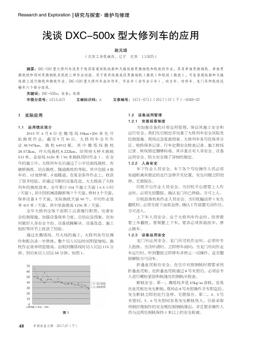
通过在魏塔线、丹大线的施工,大修列各号位操作和配合进一步熟练,整个切入切出时间明显缩短,换枕作业效率明显提高。
由刚到魏塔线时切入切出115分钟,到后来切入切出58分钟,如图1。
图11.2 设备运用管理1.2.1 完善规章制度为加强设备的日常运用管理,保证其施工安全和运行安全,我们先后制定并完善了大修列车安全风险及控制措施、现场应急复救预案、大修列车各号位保养分区、检修保养记录、行车定期安全检查记录、施工转线记录、转线锁定捆绑标准。
其中重点对人身安全、设备运用安全、防火安全做了详细的规定。
1.2.2 人身安全车下作业人员安全。
车下各个号位操作人员必须知道距离其最近的走行急停开关位置,发生问题立即拍停,无需报告。
旧枕平台作业人员安全。
当旧枕平台需要上人作业时,必须先拍警报,确认龙门吊已停稳,方可上人。
环境因素识别及评价表-DXC范本

状态
√ √ √ √ √ √ √ √
√ √ √ √ √ √ √ √ √ √ √ √ √
第 5 页,共 57 页
部门
编号:FM-QC-04源自环境因素识别及评价表产品/过程 /活动 材料(含水/ 电/原辅料 等) 水 使用消防栓 环境类别 设备/设 施 环境因素 部门 人事行政部 人事行政部 人事行政部 人事行政部 人事行政部 人事行政部 人事行政部 人事行政部 人事行政部 人事行政部 人事行政部 人事行政部 人事行政部 人事行政部 人事行政部 人事行政部 人事行政部 人事行政部 人事行政部 √ √ √ √ √ √ √ √ √ √ √ √ √ √ √ √ √ √ 水 气 声
废 弃 物
第 DXC 时态
能 / 资
页 页
共
土 壤
其 它
过 去
法规是否 发生 相关方环 影响 危险 境投诉 符合 现 将 正 异 紧 的可 大小 级别 在 来 常 常 急 YES NO 能性 YES NO √ √ √ √ √ √ √ √ √ √ √ √ √ √ √ √ √ √ √ √ √ √ √ √ √ √ √ √ √ √ √ √ √ √ √ √ √ √ √ √ √ √ √ √ √ √ √ 4 4 4 4 4 4 4 4 4 4 4 4 4 4 4 3 4 3 2 2 1 1 1 1 1 1 1 1 1 1 1 1 1 1 1 2 1 2 1 1 2 2 2 2 2 2 2 2 2 2 2 2 2 2 2 3 2 3 1 1 √ √ √ √ √ √ √ √ √ √ √ √ √ √ √ √ √ √ √ √
废 弃 物
第 DXC 时态
能 / 资
页 页
共
土 壤
其 它
过 去
法规是否 发生 相关方环 影响 危险 境投诉 符合 现 将 正 异 紧 的可 大小 级别 在 来 常 常 急 YES NO 能性 YES NO √ √ √ √ √ √ √ √ √ √ √ √ √ √ √ √ √ √ √ √ √ √ √ √ √ √ √ √ √ √ √ √ √ √ √ √ √ √ √ √ √ √ √ √ √ √ √ √ √ √ √ √ √ √ √ √ √ √ √ √ 4 3 4 4 4 4 3 4 4 4 4 4 4 4 4 4 4 4 4 4 1 2 1 1 1 1 2 1 1 1 1 1 1 1 1 1 1 1 1 1 2 3 2 2 2 2 3 2 2 2 2 2 2 2 2 2 2 2 2 2 √ √ √ √ √ √ √ √ √ √ √ √ √ √ √ √ √ √ √ √
Daikin DXC 1600 16 SEER 单阶空调产品说明书

Product Specifications1½ THRU 5 TONS SPLIT SYSTEM — 208 / 230 Volt, 1-phase, 60 HzREFRIGERATION CIRCUIT•Scroll compressors on all models•Filter-drier supplied with every unit for field installation •External high and low refrigerant service ports •Copper tube / aluminum fin coilPERFORMANCE•Communicating, self-configuring operation when used with Ion®System Control (SYST0101CW)•Outdoor temperature sensor factory installed •Compressor sound blanket standard •Isolation compressor grommetsEASY TO INSTALL AND SERVICE•Text based diagnostics with Ion® System Control •Easy access service valves on all models •Innovative control box design •High and low pressure switches•Only two screws to access control panel •Factory charged with R-410A refrigerantBUILT TO LAST•High gloss, baked-on powder coat finish over galvenized steel •Post-painted (black) coil fins•Coated, weather-resistant cabinet screws•Coated inlet grille with 3/8" (10mm) spacing for extra protection •Corner posts for extra strength and styleLIMITED WARRANTY*•5-year No Hassle Replacement™ limited warranty•5-year parts limited warranty (include compressor & coil)A210048AAA210087- With timely registration, an additional 5-year parts limited warranty (including compressor and coil)*For residential applications only. See warranty certificate for complete details and restrictions, including warranty coverage for other applications.HSA6DXC 160016 SEER Single-Stage Air Conditionerwith Ion® Communicating SystemUse of the AHRI Certi fi ed TM Mark i ndi cates a manufacturer’s participation in the program. For verification of certification for individual products,go to .SYST0101CW(Sold Separately)Th s product has been des gned and manufa ctured to meet ENERGY ST AR criteria for energy efficiency when matched w i th appropr i ate co i l componen ts. However,proper refri gerant charge and proper ai r flow are cri ti cal to ach eve rate d capa c ty and eff c ency. Installat on of thi s product shou ld follow the manufa cturer’s refri gerant charg i ng and a i r flow i nstruct i ons. Fa i lure to conf i rm proper charge and ai rflow may redu ce energy effi ci ency and shorten equipment life.Model Number Size (tons)Nominal Btu/hr Min. Circuit AmpacityMax. Fuse or BreakerOperating Dimensionsheight x width x depth in. (mm)Ship / Operating Weight lbs. (kg)HSA618GKA 1½18,00011.82028-9/16 x 31-3/16 x 31-3/16(726 x 792 x 792)213 / 176(96 / 80)HSA624GKA 224,00017.62528-9/16 x 31-3/16 x 31-3/16(726 x 792 x 792)212 / 176(96 / 80)HSA630GKA 2½30,00016.72532 x 31-3/16 x 31-3/16(813 x 792 x 792)223 / 187(101 / 85)HSA636GKA 336,00018.13029-7/8 x 35 x 35(760 x 889 x 889)243 / 200(110 / 91)HSA642GKA 3½42,00023.64040-1/8 x 35 x 35(1019 x 889 x 889)297 / 253(135 / 115)HSA648GKA 448,00026.14040-1/8 x 35 x 35(1019 x 889 x 889)340 / 295(155 / 114)HSA660GKB560,00032.45046-7/8 x 35 x 35(1191 x 889 x 889)374 / 327(169 / 148)HSA6: Product SpecificationsTable 1 – Outdoor Unit Model Number Identification Guide (single phase)Digit Position:12345, 6789101112Example Part Number:HSA618GKA1Arcoaire MainlineBRANDINGS = Single Stage Communicating KEYCHARACTERISTICA = Air Conditioner H = Heat Pump TYPE3 = 13 SEER4 = 14 SEER5 = 15 SEER6 = 16 SEER7 = 17 SEER8 = 18 SEERNOMINAL EFFICIENCY18 = 18,000 BTUH = 1½ tons NOMINAL CAPACITY 24 = 24,000 BTUH = 2 tons 30 = 30,000 BTUH = 2½ tons 36 = 36,000 BTUH = 3 tons 42 = 42,000 BTUH = 3½ tons 48 = 48,000 BTUH = 4 tons 60 = 60,000 BTUH = 5 tons A = Standard Grille G = Coil Guard Grille C = Coastal FEATURESK = 208/230-1-60VOLTAGESales CodeEngineering Revision Extra Digit Extra DigitTable 2 – Accessories Part Number Identification GuideDigit Position:1234 5 6, 78, 910, 11Example Part Number:NASA0 101C HN = Non-Branded A = AccessoryPRODUCT GROUPS = Split System (AC & HP)KIT USAGEA = OriginalB = 2nd GenerationMAJOR SERIES0 = Generic or Not Applicable 4 = R-410AREFRIGERANTProduct Identifier Number Package QuantityType of Kit (Example: CH = Crankcase Heater)FLA - Full Load Amps; LRA - Locked Rotor Amps; MCA - Minimum Circuit Amps; RLA - Rated Load Amps NOTES :1.Control circuit is 24V on all units and requires external power source.2.Copper wire must be used from service disconnect to unit.3.All motors/compressors contain internal overload protection.plies with 2007 requirements of ASHRAE Standards 90.1NOTE : Tested in accordance with AHRI Standard 270-08 (not listed in AHRI).Table 3 – Physical DataModel Size 18243036424860Compressor Type Scroll REFRIGERANTR-410AControl TXV (R-410A Hard shutoff)Charge lb (Kg) 5.25(2.38)6.00(2.72)6.81(3.09)7.00(3.18)8.62(3.91)13.00(5.9)14.00(6.35)COND FAN Propeller Type, Direct DriveAir Discharge Vertical Air Qty (CFM)2233261426143223381040464700Motor HP 1/121/101/101/121/51/41/3Motor RPM 800800800800800800815COND COIL Face Area (Sq ft)15.0715.0717.2217.5825.1225.1230.14Fins per In.25252525252020Rows 1111122Circuits34446712VALVE CONNECT. (In. ID)Vapor 3/43/43/47/87/87/87/8Liquid3/83/83/83/83/83/83/8REFRIGERANT TUBES (In. OD)Rated Vapor **.Units are rated with 25 ft (7.6 m) of lineset length. See Vapor Line Sizing and Cooling Capacity Loss table when using other sizes and lengths of lineset.3/47/81-1/8Max Liquid Line3/8”Table 4 – Electrical DataUNIT SIZEV/PHOPER VOLTS **.Permissible limits of the voltage range at which the unit will operate satisfactorily COMPR FAN MCA MAX FUSE †or CKT BRK AMPS†.Time-Delay fuse.MAX MINLRA RLA FLA 18208/230/125319748.09.00.4511.8202458.313.50.7017.5253064.012.80.7016.7253677.014.10.6018.23042112.017.9 1.0023.44048109.019.9 1.2026.14060152.523.72.8032.450Table 5 – A-Weighted Sound Power (dBA)UNIT SIZESTANDARD RATINGTYPICAL OCTAVE BAND SPECTRUM (without tone adjustment)1252505001000200040008000186652.056.560.561.559.053.544.5246751.558.061.562.559.554.047.5306856.560.063.062.559.554.546.0366955.561.062.062.561.057.049.0426853.060.562.063.060.558.051.0487055.061.063.563.060.557.052.0607367.068.068.071.063.055.052.0Units are factory charged for 15 ft (4.6 m) of 3/8" liquid line. The factory charge for 3/8" lineset 9 oz. When using other length or diameter liquid lines, charge adjustments are required per the chart above. Charging Formula:[(Lineset oz/ft x total length) – (factory charge for lineset)] = charge adjustmentExample 1:System has 15 ft of line set using existing 1/4" liquid line. What charge adjustment is required?Formula:(.27 oz/ft x 15ft) – (9 oz) = (-4.95) oz.Net result is to remove 4.95 oz of refrigerant from the system. Example 2:System has 45 ft of existing 5/16" liquid line. What is the charge adjustment?Formula:(.40 oz/ft. x 45ft) – (9 oz.) = 9 oz.Net result is to add 9 oz of refrigerant to the system.NOTE: Conditions must be favorable for charging by subcooling method. Indoor temperature must be 70°F to 80°F (21.1°C to 26.7°C), and outdoor temperature must be 70°F to 100°F (21.1°C to 37.8°C). If outside these conditions, adjust charge for long line sets by weigh-in method.Long Line ApplicationsAn application is considered Long Line, when the refrigerant level in the system requires the use of accessories to maintain acceptable refrigerant management for systems reliability. See Accessory Usage Guideline table for required accessories. Defining a system as long line depends on the liquid line diameter, actual length of the tubing, and vertical separation between the indoor and outdoor units.For Air Conditioner systems, the charts below shows when an application requires a TXV and long line accessories due to lineset length.For Air Conditioner systems, the charts below show when an application is considered Long Line:Table 6 – Charging Subcooling (TXV-Type Expansion Device) UNIT SIZE REQUIRED SUBCOOLING °F (°C) 1810 (5.6)2410 (5.6)3010 (5.6)3610 (5.6)429 (5.0)4810 (5.6)609 (5.0)Table 7 – Refrigerant Charge AdjustmentsLiquid Line Size R-410A Charge oz/ft (g/m)3/80.60 (17.74)(Factory charge for lineset = 9 oz / 266.16 g)5/160.40 (11.83)1/40.27 (7.98)Table 8 – AC with R-410A Refrigerant Long Line Description ft (m) Beyond these lengths, a TXV is required Total Length Outdoor Unit Above or Below Indoor Unit TXV required beyond 50 ft. (15.2 m)TXV required beyond 20 ft. (6.1 m)Table 9 – AC with R-410A Refrigerant Long Line Description ft (m) (Beyond these lengths, long line accessories are required) Liquid Line Size Units On Same Level Outdoor Below Indoor Outdoor Above Indoor1/4 + TXV No accessories needed within allowedlengthsNo accessories needed withinallowed lengths175 (53.3)5/16 + TXV120 (36.6)50 (15.2) vertical or 120 (36.6) total120 (36.6) 3/8 + TXV80 (24.4)35 (10.7) vertical or 80 (24.4) total80 (24.4)Vapor Line Sizing and Cooling Capacity LossAcceptable vapor line diameters provide adequate oil return to the compressor while avoiding excessive capacity loss. The suction line diameters shown in the chart below are acceptable for AC systems with R-410A refrigerant:NOTE: For coils not listed with a matching furnace or blower, coil rating applies with any indoor blower device.AHRI RATINGSFor AHRI ratings certificates, please refer to the AHRI directory Additional ratings and system combinations can be accessed via the Ratings Database here: Arcoaire RatingsTable 10 – Vapor Line Sizing and Cooling Capacity Losses — R-410A Refrigerant 1-Stage Air Conditioner ApplicationsUnitNominalSize (Btuh)MaximumLiquid LineDiameters(In. OD)Vapor Line Diameters (In. OD)Cooling Capacity Loss (%)Total Equivalent Line Length ft. (m)26-50 (7.9-15.2)51-80 (15.5-24.4)81-100(24.7-30.5)101-125 (30.8-38.1)126-150 (38.4-45.7)151-175 (46.0-53.3)176-200 (53.6-61.0)201-225 (61.3-68.6)226-250 (68.9-76.2)181 Stage ACwith R-410A 3/81/21235678911 5/80111222333/4000011111241 Stage ACwith R-410A 3/85/8012233455 3/4001111122 7/8000001111301 Stage ACwith R-410A 3/85/8123345678 3/4001112223 7/8000011111361 Stage ACwith R-410A 3/85/812456891012 3/4011223344 7/8000111122421 Stage ACwith R-410A 3/83/4012234456 7/80011122231 1/8000000000481 Stage ACwith R-410A 3/83/4012345567 7/80011222331 1/8000000011601 Stage ACwith R-410A3/83/412456791011 7/80122344551 1/8111111Consult the Long Line Application Guideline document before purchasing/installing line sets.Applications in shaded area may have height restrictions that limit allowable total equivalent length when outdoor unit is below indoor unit.Table 11 – AHRI Standard RatingsUnit Size Indoor Model Furnace ModelCooling 95°F (35°C)Capacity Factory Enhance SEEREER StandardW/ Field TDR W/ Field TXVHSA618GKA *EN(A,D)4X19*17**18000TXV 14.512.0HSA624GKA *EN(A,D)4X31*17**23800TXV 14.512.0HSA630GKA *EN(A,D)4X31*17**28400TXV 14.512.0HSA636GKA *EN(A,D)4X37*17**34400TXV 14.512.0HSA642GKA *EN(A,D)4X43*24**42000TXV 14.512.0HSA648GKA *EN(A,D)4X61*24**46500TXV 14.512.5HSA660GKB*EN(A,D)4X61*24**57500TXV15.012.5Condenser Only Ratings*See notes on pg. 13SST °F (°C)CONDENSER ENTERING AIR TEMPERATURES °F (°C)55 (12.78)65 (18.33)75 (23.89)85 (29.44)95 (35.0)105 (40.56)115 (46.11)125 (51.67)*SA618GKA30(-1.11)TCG 14.0013.5013.0012.4011.8011.0010.209.30SDT 65.2074.8084.4094.00103.60113.10122.60132.00KW 0.660.780.91 1.04 1.20 1.37 1.58 1.8335(1.67)TCG 15.6015.0014.5013.8013.1012.3011.4010.40SDT 66.3075.9085.4094.90104.40113.80123.20132.70KW 0.650.770.90 1.04 1.20 1.38 1.58 1.8340(4.44)TCG 17.3016.7016.1015.3014.6013.7012.7011.70SDT 67.5076.9086.4095.80105.20114.60124.00133.30KW 0.640.770.90 1.05 1.20 1.38 1.59 1.8345(7.22)TCG 19.1018.5017.7017.0016.1015.2014.2013.00SDT 68.7078.0087.4096.70106.10115.40124.80134.10KW 0.630.770.90 1.05 1.21 1.39 1.59 1.8350(10.0)TCG 21.1020.3019.5018.7017.8016.7015.7014.50SDT 69.9079.2088.4097.70107.00116.30125.60134.80KW 0.630.760.90 1.05 1.21 1.39 1.60 1.8455(12.78)TCG 23.1022.3021.5020.5019.5018.4017.2015.90SDT 71.2080.4089.6098.80108.00117.20126.50135.60KW 0.620.760.91 1.06 1.22 1.401.61 1.85*SA624GKA30(-1.11)TCG 20.1019.4018.5017.6016.7015.6014.4013.10SDT 66.1075.8085.3094.90104.40114.00123.40132.80KW 0.97 1.13 1.29 1.46 1.65 1.87 2.13 2.4235(1.67)TCG 22.3021.4020.5019.5018.5017.3016.0014.70SDT 67.2076.8086.3095.80105.30114.70124.10133.50KW 0.96 1.12 1.29 1.46 1.66 1.87 2.13 2.4240(4.44)TCG 24.6023.7022.7021.6020.4019.1017.8016.30SDT 68.4077.9087.3096.70106.10115.50124.80134.10KW 0.95 1.12 1.29 1.46 1.66 1.88 2.13 2.4245(7.22)TCG 27.1026.0024.9023.7022.4021.1019.6018.00SDT 69.6079.0088.3097.60107.00116.30125.60134.90KW 0.94 1.11 1.29 1.47 1.67 1.89 2.14 2.4350(10.0)TCG 29.7028.6027.3026.0024.6023.1021.5019.80SDT 70.8080.1089.4098.70107.90117.20126.40135.60KW 0.93 1.11 1.29 1.47 1.67 1.90 2.15 2.4355(12.78)TCG 32.5031.2029.9028.4026.9025.3023.5021.70SDT 72.1081.3090.5099.70108.90118.10127.30136.40KW 0.93 1.11 1.29 1.48 1.69 1.912.16 2.45*SA30GKA30(-1.11)TCG 23.8022.9021.9020.9019.8018.5017.0015.30SDT 68.1077.5087.0096.40105.80115.10124.40133.60KW 1.14 1.32 1.52 1.74 1.99 2.29 2.63 3.0235(1.67)TCG 26.3025.3024.3023.1021.9020.5019.0017.20SDT 69.4078.7088.1097.40106.70116.00125.30134.40KW 1.15 1.33 1.52 1.75 2.00 2.30 2.64 3.0340(4.44)TCG 29.0027.9026.8025.5024.2022.8021.1019.20SDT 70.7079.9089.2098.50107.70117.00126.20135.30KW 1.16 1.33 1.53 1.75 2.01 2.31 2.65 3.0545(7.22)TCG 31.9030.7029.4028.1026.7025.1023.4021.40SDT 72.0081.2090.4099.60108.80118.00127.20136.30KW 1.16 1.33 1.53 1.76 2.01 2.31 2.66 3.0650(10.0)TCG 35.0033.6032.3030.8029.3027.6025.7023.60SDT 73.5082.5091.60100.80110.00119.20128.20137.20KW 1.16 1.33 1.53 1.76 2.02 2.32 2.67 3.0755(12.78)TCG 38.3036.8035.3033.7032.0030.2028.2026.00SDT 75.0084.0093.00102.10111.20120.30129.30138.20KW1.151.331.53 1.762.02 2.322.673.08SST °F (°C)CONDENSER ENTERING AIR TEMPERATURES °F (°C)55 (12.78)65 (18.33)75 (23.89)85 (29.44)95 (35.0)105 (40.56)115 (46.11)125 (51.67)*SA636GKA30 (-1.11)TCG30.5029.2027.8026.3024.7023.0021.2019.20 SDT69.5078.7087.9097.20106.60115.90125.20134.50 KW 1.41 1.62 1.85 2.10 2.37 2.69 3.07 3.5135 (1.67)TCG33.7032.2030.7029.1027.4025.5023.6021.50 SDT70.7079.9089.1098.30107.50116.80126.10135.40 KW 1.41 1.63 1.86 2.11 2.38 2.70 3.07 3.5140 (4.44)TCG37.1035.5033.8032.1030.2028.2026.1023.90 SDT72.1081.2090.3099.50108.60117.80127.10136.30 KW 1.42 1.64 1.87 2.12 2.40 2.71 3.08 3.5245 (7.22)TCG40.8039.0037.2035.3033.2031.1028.8026.40 SDT73.7082.6091.60100.70109.80118.90128.10137.20 KW 1.43 1.65 1.88 2.13 2.41 2.73 3.10 3.5350 (10.0)TCG44.8042.8040.8038.7036.5034.1031.7029.00 SDT75.3084.1093.10102.00111.00120.10129.10138.10 KW 1.45 1.67 1.90 2.15 2.43 2.75 3.12 3.5455 (12.78)TCG48.9046.8044.6042.3039.9037.4034.7031.80 SDT77.0085.7094.60103.40112.30121.30130.20139.10 KW 1.47 1.70 1.93 2.18 2.46 2.77 3.14 3.56*SA642GKA30 (-1.11)TCG33.0032.3031.4030.3028.9027.4025.6023.70 SDT69.8079.2088.7098.10107.40116.70125.90135.10 KW 1.61 1.84 2.12 2.45 2.84 3.29 3.81 4.4035 (1.67)TCG36.4035.7034.7033.4032.0030.3028.4026.30 SDT71.2080.6089.9099.20108.40117.70126.80136.00 KW 1.62 1.86 2.14 2.47 2.86 3.31 3.83 4.4240 (4.44)TCG40.1039.3038.2036.8035.2033.4031.4029.10 SDT72.7081.9091.20100.40109.60118.70127.80136.90 KW 1.63 1.87 2.15 2.49 2.88 3.33 3.85 4.4545 (7.22)TCG44.1043.1041.9040.4038.6036.7034.5032.00 SDT74.2083.3092.50101.60110.80119.90128.90137.90 KW 1.64 1.88 2.17 2.51 2.91 3.36 3.88 4.4850 (10.0)TCG48.3047.2045.8044.2042.3040.1037.7035.00 SDT75.8084.8093.90103.00112.00121.00130.00138.90 KW 1.65 1.90 2.19 2.54 2.94 3.39 3.92 4.5155 (12.78)TCG52.8051.5050.0048.1046.0043.7041.1038.20 SDT77.4086.4095.40104.40113.40122.30131.20140.00 KW 1.67 1.92 2.22 2.57 2.97 3.43 3.96 4.55*SA648GKA30 (-1.11)TCG40.1038.0035.9033.8031.5029.2026.7024.20 SDT67.6077.0086.4095.80105.10114.50123.80133.10 KW 1.97 2.26 2.54 2.83 3.13 3.46 3.84 4.2935 (1.67)TCG44.4042.0039.7037.3034.8032.3029.6026.80 SDT68.9078.2087.5096.80106.10115.30124.60133.80 KW 1.90 2.22 2.53 2.83 3.14 3.48 3.87 4.3040 (4.44)TCG49.1046.4043.8041.1038.4035.6032.7029.60 SDT70.3079.4088.6097.80107.00116.30125.40134.60 KW 1.80 2.15 2.49 2.81 3.14 3.50 3.89 4.3245 (7.22)TCG54.2051.2048.2045.2042.2039.2036.0032.60 SDT71.7080.7089.8099.00108.10117.30126.40135.40 KW 1.66 2.05 2.41 2.77 3.13 3.50 3.90 4.3450 (10.0)TCG59.8056.4053.0049.7046.4043.0039.4035.70 SDT73.2082.1091.20100.20109.30118.30127.30136.30 KW 1.47 1.90 2.31 2.70 3.09 3.48 3.90 4.3555 (12.78)TCG65.8062.0058.3054.5050.8047.0043.1039.00 SDT74.8083.6092.60101.50110.50119.40128.40137.30 KW 1.24 1.72 2.17 2.60 3.02 3.44 3.88 4.35See notes on pg. 13* AHRI listing applies only to systems shown in Combination Ratings table.KW - Outdoor Unit Kilowatts Only.SDT -Saturated Temperature Leaving Compressor (°F/°C)SST -Saturated Temperature Entering Compressor (°F)TCG -Gross Cooling Capacity (1000 Btuh)SST °F (°C)CONDENSER ENTERING AIR TEMPERATURES °F (°C)55 (12.78)65 (18.33)75 (23.89)85 (29.44)95 (35.0)105 (40.56)115 (46.11)125 (51.67)*SA660GKB30 (-1.1)TCG 52.2049.6047.0044.3041.5038.6035.4032.10SDT 70.6080.0089.6099.20108.80118.50128.20137.80KW 2.68 3.02 3.39 3.81 4.29 4.84 5.48 6.2035 (1.7)TCG 57.5054.7051.8049.0045.9042.7039.3035.80SDT 71.9081.3090.90100.30109.90119.50129.20138.80KW 2.71 3.04 3.42 3.84 4.32 4.87 5.52 6.2440 (4.4)TCG 63.2060.1057.0053.9050.6047.1043.5039.70SDT 73.4082.7092.10101.60111.20120.70130.20139.80KW 2.74 3.07 3.44 3.87 4.36 4.92 5.55 6.2845 (7.2)TCG 69.4066.0062.6059.2055.6051.9047.9043.90SDT 75.0084.1093.50102.90112.40121.80131.40140.90KW 2.76 3.09 3.47 3.90 4.39 4.95 5.61 6.3350 (10)TCG 75.9072.3068.5064.8060.9056.9052.7048.30SDT 76.6085.7095.10104.40113.70123.10132.60141.90KW 2.78 3.12 3.50 3.93 4.42 4.99 5.65 6.3855 (12.8)TCG 82.9079.0075.0070.9066.7062.3057.8053.10SDT 78.4087.3096.40105.70115.10124.40133.70143.00KW2.803.153.523.964.465.025.686.42© 2021 Carrier. All rights reserved.A Carrier Company Edition Date: 08/21Catalog No: 421 31 1402 06Replaces: 21 31 1402 05‡ Non-communicating thermostat required.* Refer to the Long Line Application Guideline document +If unit equipped with ECM OD motor, both motor and fan need to be replaced per unit accessory guide to work properly. Unit will not meet AHRI rated efficiency once motor and fan are replaced to use this accessory.{ TXV required beyond 20 ft. (6.1 m) vertical separation or 50 ft. (15.2 m) total length.*Some models may be factory installed.Table 12 – Accessory Usage GuidelinesACCESSORYRequired for Low Ambient Cooling Applications (Below 55°F / 12.8°C)‡Required for Low Ambient Cooling ApplicationsUtilizing UI(below 55°F / 12.8°CRequired for Long LineApplications*Compressor Start Assist Capacitor and RelayYes NoYes Crankcase Heater Yes Yes. Standard on some units Yes Evaporator Freeze Thermostat Yes Standard with Ion® control(no kit required)No Low-ambient Pressure Switch +Yes Standard with Ion® control(no kit required)No Support FeetRecommendedRecommended No Thermal Expansion Valve (TXV)Hard ShutoffYes Yes (Standard with factory approved indoor unit)Yes {Winter Start ControlYesYesNoTable 13 – AccessoriesPart Number DescriptionUsed On Model SizeNASA003CH Crankcase Heater for Scroll Compressor (208/230 V)18, 24, 30, 36NASA001CH Crankcase Heater for Scroll Compressor (208/230 V)42, 48, 60*NASA001SC Start Component - PTC Device ALL NASA00201FS Evaporator Freeze Thermostat ALL NASA401LS Liquid Line Solenoid Valve, R-410A ALL NASA001TD Time Delay Relay, Indoor BlowerALL NASA00201WS Winter Start Control ALL NASA001AC Anti-Cycle Timer (5 minute delay)ALL NASA014SC Hard Start Kit (Capacitor & Relay)18 - 48NASA012SC Hard Start Kit (Capacitor & Relay)60NASA401LA Low Ambient Kit (Pressure Switch), R-410AALL NASA00201SF Support Feet, 4” (102mm) tallALL NAEA40501TX TXV Kit, R-410A - for use with copper or tin fan coils 18, 24, 30NAEA40601TX TXV Kit, R-410A - for use with copper or tin fan coils 36, 42NAEA40701TX TXV Kit, R-410A - for use with copper or tin fan coils 48, 60NAEB40501TX TXV Kit, R-410A - for use with aluminum fan coils 18, 24, 30NAEB40601TX TXV Kit, R-410A - for use with aluminum fan coils 36, 42NAEB40701TX TXV Kit, R-410A - for use with aluminum fan coils48, 60SYST0101CW Ion System ControlALL 1184959PSC motor601185010Fan60。
ASD DXc 火警系统说明手册说明书

Get to know your DXc!DESIGN INSTALLThe DXc fire panel can now support 160 zones , giving the system designer greater flexibility for larger site installations Installation of the DXc fire alarm panel is complete in just 5 button presses COMMISSIONING Enhanced Sounder Control:Sounder tone and volume can now be controlled through the panel and/or configuration toolGET TO KNOW YOUR DXc!DESIGNMIMIC DELIVERING INCREASED ZONAL DETAILING BRINGING CONFIDENCE IN LOCATING FIREWhenever a system covering a large building goes into itsalarm state, Fire and Rescue Service personnel, security staff or employees often have to waste precious time cross-referencing LEDs on a panel with zonal or floor maps.• The DX Connexion panel now has adapted software that allowsa custom-built geographic map to be created, combining the LED zone indicators with the floor plan.•DESIGNLARGER SITE INSTALLATION NOW POSSIBLE THANKS TO INCREASED ZONE SUPPORTThe adaptability of the DX Connexion control panel range means it is now being used for larger and more complex sites. As a result, changes have been introduced to accommodate the expansion and give more flexibility.• The number of zones that can be supported has been doubledfrom 80 to 160 in new and existing sites.• Dedicated extension boxes have been designed to display theexpanded number of LED zone indicators below the controlDESIGNFUTURE PROOF DESIGNYou never know what the future holds, changing design requirements; additions and extensions, the DXc range is completely networkable giving you the confidence that the system provides scalable and flexible solutions.Did youknow...?INSTALLFLEXIBILITY OF INSTALLATIONOne, Two and Four loop Panels are pre built in the factory. The range is complimented by a range of accessories to suit any project requirement.Depending on the system size and standby requirements, it is possible to increase the enclosure size of a DXc1, DXc2 or DXc4 control panel by fitting an extension box to accommodate larger batteries, relays or other equipment. A range of covers can bepurchased to suit your needs and include a blank cover, customer key plate and 80 Zone LED expansion cover. If additional batteries areINSTALLFLEXIBILITY OF INSTALLATIONIn wall, on wall, in rackFlush mounting options are available to suit a variety of combinations to suit all installation requirements. Convenient cablingCOMMISSIONINGSAVE TIME AND MONEY WITH DISRUPTION FREE SOUNDER CONFIGURATIONAdjusting sounder tone and volume settings after installationcan be very disruptive, labour-intensive and expensive.• System Sensor and Morley-IAS protocol sounders can now have their individual tone and volume levels set from the DXConnexion panel, cutting out many of these difficulties. • The panel can also now synchronise all sounders across multiple loops, so that they meet safety standard requirementsabout audibility if a pulsing tone is employed.MAINTENANCEFASTER FAULT FINDINGDepending on the size of the installation, identifying double addressed devices during commissioning or servicing a systemcan be very time-consuming, to complete the commissioning process and hand over the site, the DX Connexion panel range has a new feature which reduces the time required to locate these devices.• Finding double-addressed devices is quicker because their presence is now indicated by lighting up of the detectorLEDs when at access level 3. (Detection of double-addressedDISABLE RELAYSMORE PANEL OPTIONS MEAN FASTER AND LESS DISRUPTIVE SERVICINGAccidental activation of sounders during maintenance is a realirritation for everyone in a busy workplace or public building with the potential for lost revenue. The DX Connexion panel range now has a special feature to cut out this disruption.• A new ‘Disable all Relays’ panel option means outputs including visual and audible alarm devices cannot be accidentally set off during servicing.• The new option can also be activated by configurable panelMUTE BUZZERSREDUCED CUSTOMER DISTURBANCEA buzzing panel can be an irritant for people local to the panel when a system is being serviced. To counter this irritation, theDX Connexion panel range now supports an engineering mode which reduces the disturbance.• An ‘engineering mode’ mutes the panel buzzer for a set periodwhile the system is serviced• Automatic cancellation after the set period means the mode cannot accidentally be left active by mistake if the engineerforgets to clear it.GET TO KNOW YOUR DXc!26KM1SD4HV 12345687910TYPE B DEPENDENCYCUT OUT UNNECESSARY EVACUATIONS WITH INCREASED CAUSE AND EFFECT CAPABILITY Reducing costly and time-wasting false alarms is a major aim for any building operator or business. The DX Connexion upgrade now allows fire wardens or security staff to investigate the cause of the alarm before evacuation is activated .• An in-built Type B dependencymeans that when a single detectorindicates fire, it is shown on thepanel’s LCD but not on its fire LED.。
数字交叉连接设备DXC1/0常见故障解决方案

性窗口 , 检查 物 理 地 址、 串 口号 、类 型 、设备 位置 等 填 写 属性 内容 是否 正确 。特 别 需要注 意 的物 理 地 址属 性 内容 , 必 须 与后
台物理地 址 相 同。
入 端 口数 字 流 的最 高等 级 ,Y表 示参 与交 叉 连接 的数字 流 的 最
低 等 级 。x 、Y为数 字 0 - 6 , 其中: 0 表示 6 4 k b / s电路 速 率 ; 1
故障也频繁 出现 , 丈章针对在 D X C 设备应用中经常出现的故障特点进行分析 , 并提供相应的解决方案 。
关键 词 数 字 交叉 连接设 备 ; S D H系统 ; D X C 中图分类 号 : T N 9 1 5 文献 标识 码 : A
D X C具 有 一 个 或 多 个 I T U — T建 议 G . 7 0 2或 G . 7 0 7定 义 的 数 字 信号 速 率端 口 , 这 些 端 口可 以实现 同其 它 端 口信 号速 率 间 的 可 控连接 和 再连接 。 根 据不 同的速率 , D X C 可 以有 各种配置 形 式 ,
源 ”属性 窗 口查 看 后 台 同步时 钟 配 置情 况 。再与 维 护 台终 端配
提 出 了解 决 的方案 。
1 维护 终端取 不到 系统 配置
D X C 1 / O通过 软件 配 置 方 式 实 的连接 和拆除 , 替代 多 台 P C M 终端机 , 节 约线 路及 设备 资源 。 D X C 1 / O 设 备也是 通过 维 护 终端 控 制 的方式 完成 通信 网 的 电路 调 度 、网络 监 控与 管理 和 测 试接 入 等 , 因此 维 护终 端 与系 统 之 间 的 配置 连接 就起 到 非 常 重要 的 作用 。 当维护 终 端 取不 到系 统 配 置时 , 对 系 统 的设 置和 运 行 造 成很 大 的影 响 , 在 维护 终端 上 的 各 种操 作 都会无 效 , 特 别 是 正在 运 行 的后 台设 备 的各 种现 行 配 置 不 能读 取 到连接 D X C设 备 的维 护 终端 上 , 也 就造 成 系统 取 不 到 后台配置 , 出现 这种 情 况可 以从 以下 3个方 面进 行检查 。 1 )检查 D X C 到维 护 终端 线路 。飞鸿 D X C I / O 通过 2 个R S 2 3 2
- 1、下载文档前请自行甄别文档内容的完整性,平台不提供额外的编辑、内容补充、找答案等附加服务。
- 2、"仅部分预览"的文档,不可在线预览部分如存在完整性等问题,可反馈申请退款(可完整预览的文档不适用该条件!)。
- 3、如文档侵犯您的权益,请联系客服反馈,我们会尽快为您处理(人工客服工作时间:9:00-18:30)。
面
中兴通讯学院
<本文中的所有信息归中兴通讯股份有限公司所有,未经允许,不得外传>
二、DXC16数据配置
2)建网络拓扑图、增加 设备、建立通讯连线
双击<日常维护>→ <新 建网络拓扑数据> ,建 网络拓扑图 双击<设备管理>;再双 击<新建设备>; 双击<网管串口主机>; 再双击<DXC-16时隙交叉 收敛设备 连续双击电脑图标与 DXC图标,使电脑图标与 DXC图标之间相连,相连 后电脑图标与DXC图标之 间有一绿色连线
<本文中的所有信息归中兴通讯股份有限公司所有,未经允许,不得外传>源自一、DXC16原理介绍
3、 DXC16性能
• DXC16满配置为32个端口输入,32个端口输出的平衡设
计。设备时隙交叉连接能力为32×32 × 31 × 31 , 同时支持高速2M和64K。
• DXC16支持时隙复制,在相同或不同的输出口上同时输
中兴通讯学院
<本文中的所有信息归中兴通讯股份有限公司所有,未经允许,不得外传>
一、DXC16原理介绍
由于采集设备的特性,DXC16输出只用传输2M电路的 收方向。
DXC16
OUT(输出口)
A
发
传输
收
B
采集机
传输
收
发
中兴通讯学院
<本文中的所有信息归中兴通讯股份有限公司所有,未经允许,不得外传>
DXC16
在该2M上1~31时隙均可以走信令
中兴通讯学院
<本文中的所有信息归中兴通讯股份有限公司所有,未经允许,不得外传>
一、DXC16原理介绍
2、 DXC16结构
ZXT2000-DXC16为插卡式结构,每台配置1个DXC基本模块 和E1接口模块。 DXC基本模块包括机框、背板、电源、主控板。 每个E1接口模块有8个单向E1信号输入口,8个单向E1信 号输出口。 可插1-4块E1接口模块。
中兴通讯学院
<本文中的所有信息归中兴通讯股份有限公司所有,未经允许,不得外传>
1) 背面视图
一、DXC16原理介绍
中兴通讯学院
<本文中的所有信息归中兴通讯股份有限公司所有,未经允许,不得外传>
2)正面视图
一、DXC16原理介绍
中兴通讯学院
一、DXC16原理介绍
解决方法:
1)通过交换机控制台屏蔽传输交换机告警信号。 2)在数据采集中心的传输DDF架上把传输交换机的收发端用 三通进行自环,使空闲的传输通路有数据返回从而达到消除 传输交换机无信号告警的目的。然后再从传输的发端口分流 一信号到采集设备进行数据采集
中兴通讯学院
<本文中的所有信息归中兴通讯股份有限公司所有,未经允许,不得外传>
一、DXC16原理介绍
5、板位及端口号
IFB1表示第一板位,IFB2表示第二板位,以此类推。 每块板上面有端口共16个,其中输入8个(横向排列),输出8 个(横向排列),输入口用“IN”表示,输出口用“OUT”表示。 每个端口下方都有该端口所在IFB接口板上的位号。
4、DXC16信令采集与传输
• 一个信令端子(2M)有收方向和发方向,因这两个方
向内的实时信令数据不同,所以采集设备必须把这两 个方向同时采集,同时输入到DXC16上。就是说,一个 信令端子(2M)的收方向和发方向均与DXC16的输入口 相连,一个信令端子(2M)占用DXC16上两个输入口。
收敛链路的特殊性 一般通讯设备:双向(收、发) 交叉收敛设备:单向(相对信令网)
TS-010-C1
DXC16介绍
V0608
中兴通讯学院
有线网络课程团队
中兴通讯学院
<本文中的所有信息归中兴通讯股份有限公司所有,未经允许,不得外传>
课程目标
• 掌握DXC的原理 • 掌握DXC的数据配置
中兴通讯学院
<本文中的所有信息归中兴通讯股份有限公司所有,未经允许,不得外传>
中兴通讯学院
<本文中的所有信息归中兴通讯股份有限公司所有,未经允许,不得外传>
二、DXC16数据配置
3、数据配置
1)登录 用串口线连接配置主机及DXC,点击DXC配置程序 DXC16.EXE文件;登录进入网管系统
用户名为123,密码为123,点击“确定”按钮,进入下一界
出多个相同的时隙。
• DXC16设备支持根据需要的任意级级联,实现的级连方
式有:
① DXC的单级级连方式
DXC1
DXC2
② DXC的多级级连方式
DXC1
DXC2
DXC3...
中兴通讯学院
<本文中的所有信息归中兴通讯股份有限公司所有,未经允许,不得外传>
一、DXC16原理介绍
写入DXC,并保留配置文件。 4)观察DXC面板灯的状态,确认数据配置的正确性
中兴通讯学院
<本文中的所有信息归中兴通讯股份有限公司所有,未经允许,不得外传>
二、DXC16数据配置
2、数据规划 • 明确DXC16上各个输入端口所接入的链路是那个局
点的链路 • 该链路所在的时隙是多少 • 明确输出口的端口号
一、DXC16原理介绍
1、 DXC16概念
DXC16又称为交叉收敛设备,主要负责链路的分散采集, 多路收敛合成单路输出或同链路复制多路输出,从而 达到节省传输资源的目的。 DXC数据配置是通过控制台与DXC进行串口连接,通过 控制台DXC专用软件进行配置。配置在Windows界面中 完成,实现收敛设备的控制。
1脚 工作地
中兴通讯学院
<本文中的所有信息归中兴通讯股份有限公司所有,未经允许,不得外传>
3脚 保护地
二、DXC16数据配置
1、DXC16数据配置的一般步骤
1)做好数据规划 2)通过串口连接到DXC设备上,将DXC中的原有数据读出,
存为文件进行备份 3)进行数据修改,将修改好的数据通过“建立连接”操作
每个输入口当有链路接入时,对应到设备正面的指示灯亮,
中兴通讯学院
<本文中的所有信息归中兴通讯股份有限公司所有,未经允许,不得外传>
一、DXC16原理介绍
6、 DXC16电源接头示意图与接线方式
A端脚号 1 工作地 2 -48V 3 保护地
电缆 灰色 蓝色 绿黄色
缺口
2脚-48V